lock GEELY MK 2008 Service Manual
[x] Cancel search | Manufacturer: GEELY, Model Year: 2008, Model line: MK, Model: GEELY MK 2008Pages: 416, PDF Size: 25.19 MB
Page 165 of 416
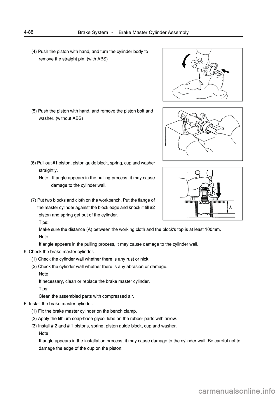
(4) Push the piston with hand, and turn the cylinder body to
remove the straight pin. (with ABS)
(5) Push the piston with hand, and remove the piston bolt and
washer. (without ABS)
(6) Pull out #1 piston, piston guide block, spring, cup and washer
straightly.
Note: If angle appears in the pulling process, it may cause
damage to the cylinder wall.
(7) Put two blocks and cloth on the workbench. Put the flange of
the master cylinder against the block edge and knock it till #2
piston and spring get out of the cylinder.
Tips:Brake System -Brake Master Cylinder Assembly4-88 Make sure the distance (A) between the working cloth and the block's top is at least 100mm.
Note:
If angle appears in the pulling process, it may cause damage to the cylinder wall.
5. Check the brake master cylinder.
(1) Check the cylinder wall whether there is any rust or nick.
(2) Check the cylinder wall whether there is any abrasion or damage.
Note:
If necessary, clean or replace the brake master cylinder.
Tips:
Clean the assembled parts with compressed air.
6. Install the brake master cylinder.
(1) Fix the brake master cylinder on the bench clamp.
(2) Apply the lithium soap-base glycol lube on the rubber parts with arrow.
(3) Install # 2 and # 1 pistons, spring, piston guide block, cup and washer.
Note:
If angle appears in the installation process, it may cause damage to the cylinder wall. Be careful not to
damage the edge of the cup on the piston.
Page 172 of 416
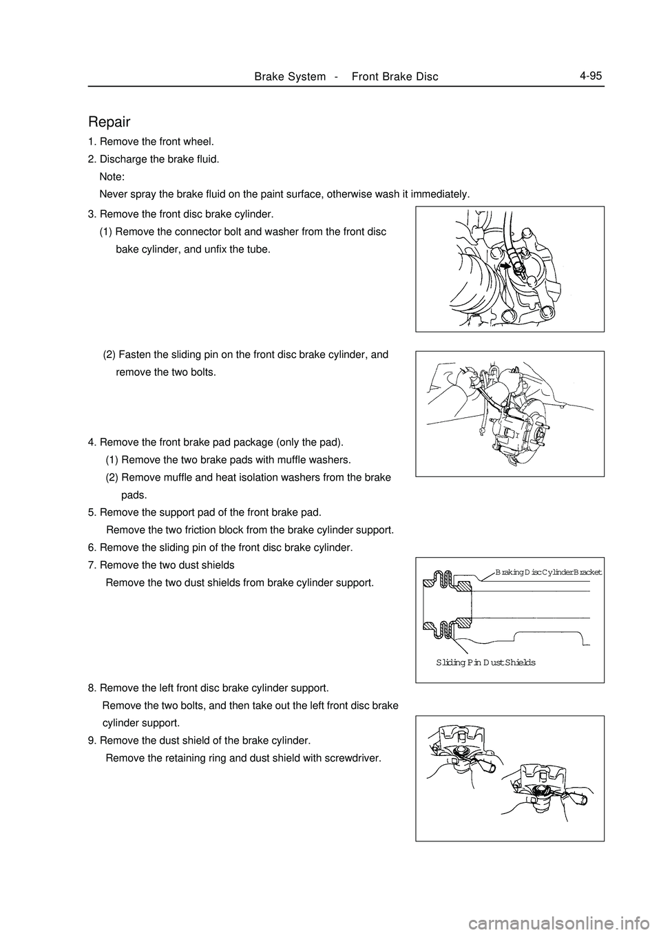
Repair1. Remove the front wheel.
2. Discharge the brake fluid.
Note:
Never spray the brake fluid on the paint surface, otherwise wash it immediately.Brake System -Front Brake Disc4-95Sliding Pin Dust Shields3. Remove the front disc brake cylinder.
(1) Remove the connector bolt and washer from the front disc
bake cylinder, and unfix the tube.
(2) Fasten the sliding pin on the front disc brake cylinder, and
remove the two bolts.
4. Remove the front brake pad package (only the pad).
(1) Remove the two brake pads with muffle washers.
(2) Remove muffle and heat isolation washers from the brake
pads.
5. Remove the support pad of the front brake pad.
Remove the two friction block from the brake cylinder support.
6. Remove the sliding pin of the front disc brake cylinder.
7. Remove the two dust shields
Remove the two dust shields from brake cylinder support.
8. Remove the left front disc brake cylinder support.
Remove the two bolts, and then take out the left front disc brake
cylinder support.
9. Remove the dust shield of the brake cylinder.
Remove the retaining ring and dust shield with screwdriver.Braking Disc Cylinder Bracket
Page 175 of 416
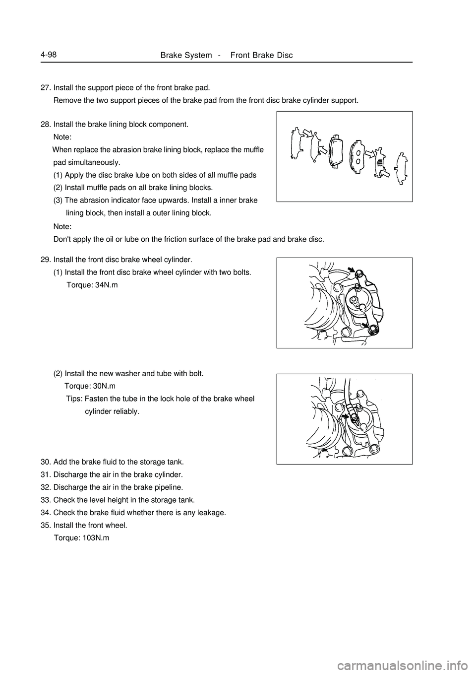
Brake System -Front Brake Disc4-9827. Install the support piece of the front brake pad.
Remove the two support pieces of the brake pad from the front disc brake cylinder support.
28. Install the brake lining block component.
Note:
When replace the abrasion brake lining block, replace the muffle
pad simultaneously.
(1) Apply the disc brake lube on both sides of all muffle pads
(2) Install muffle pads on all brake lining blocks.
(3) The abrasion indicator face upwards. Install a inner brake
lining block, then install a outer lining block.
Note:
Don't apply the oil or lube on the friction surface of the brake pad and brake disc.
29. Install the front disc brake wheel cylinder.
(1) Install the front disc brake wheel cylinder with two bolts.
Torque: 34N.m
(2) Install the new washer and tube with bolt.
Torque: 30N.m
Tips: Fasten the tube in the lock hole of the brake wheel
cylinder reliably.
30. Add the brake fluid to the storage tank.
31. Discharge the air in the brake cylinder.
32. Discharge the air in the brake pipeline.
33. Check the level height in the storage tank.
34. Check the brake fluid whether there is any leakage.
35. Install the front wheel.
Torque: 103N.m
Page 184 of 416
Brake System -Parking Brake System4-107Adjustment1. Remove the rear wheel.
2. Adjust the clearance of the brake shoe.
3. Install the rear wheel.
Torque: 103N.m
4. Check the stroke of the parking brake extension rod.
Pull the parking brake extension rod, and count the number of sound.
Parking Brake Extension Rod Stroke: Pull with 196N force till 6-9 clicks.
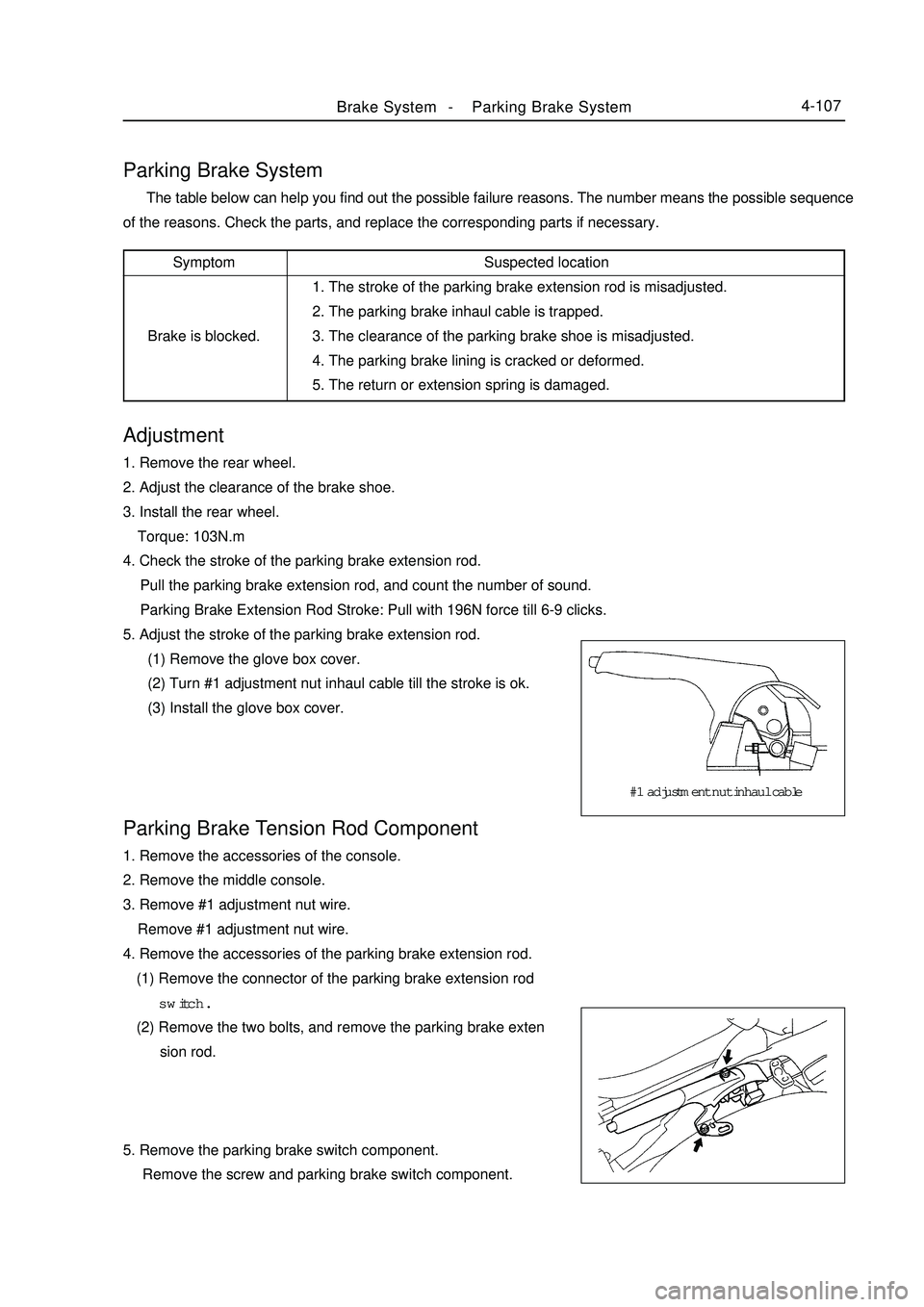
5. Adjust the stroke of the parking brake extension rod.
(1) Remove the glove box cover.
(2) Turn #1 adjustment nut inhaul cable till the stroke is ok.
(3) Install the glove box cover.Parking Brake System The table below can help you find out the possible failure reasons. The number means the possible sequence
of the reasons. Check the parts, and replace the corresponding parts if necessary.Parking Brake Tension Rod Component1. Remove the accessories of the console.
2. Remove the middle console.
3. Remove #1 adjustment nut wire.
Remove #1 adjustment nut wire.
4. Remove the accessories of the parking brake extension rod.
(1) Remove the connector of the parking brake extension rod
switch.
(2) Remove the two bolts, and remove the parking brake exten
sion rod.
5. Remove the parking brake switch component.
Remove the screw and parking brake switch component.Suspected location
1. The stroke of the parking brake extension rod is misadjusted.
2. The parking brake inhaul cable is trapped.
3. The clearance of the parking brake shoe is misadjusted.
4. The parking brake lining is cracked or deformed.
5. The return or extension spring is damaged.Symptom
Brake is blocked.#1 adjustment nut inhaul cable
Page 196 of 416
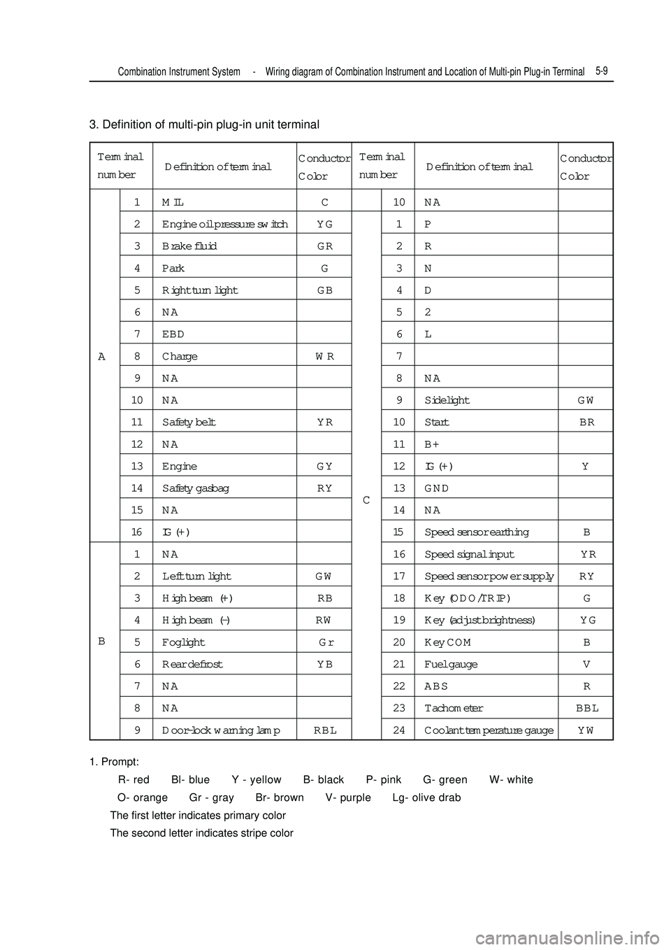
3. Definition of multi-pin plug-in unit terminal
1. Prompt:
R- red Bl- blue Y - yellow B- black P- pink G- green W- white
O- orange Gr - gray Br- brown V- purple Lg- olive drab
The first letter indicates primary color
The second letter indicates stripe colorTerminal
number1 MIL C 10 NA
2 Engine oil pressure switch YG 1 P
3 Brake fluid GR 2 R
4 Park G 3 N
5 Right turn light GB 4 D
6NA 52
7 EBD 6 L
8 Charge WR 7
9NA 8NA
10 NA 9 Sidelight GW
11 Safety belt YR 10 Start BR
12 NA 11 B+
13 Engine GY 12IG ( + ) Y
14 Safety gasbag RY 13 GND
15 NA 14 NA
16 IG ( + ) 15Speed sensor earthing B
1 NA 16 Speed signal input YR
2 Left turn light GW 17 Speed sensor power supply RY
3 High beam (+) RB 18 Key (ODO/TRIP) G
4 High beam (-) RW 19 Key (adjust brightness) YG
5 Foglight Gr 20 Key COM B
6 Rear defrost YB 21 Fuel gauge V
7 NA 22 ABS R
8 NA 23 Tachometer BBL
9 Door-lock warning lamp RBL 24 Coolant temperature gauge YWA
BCCombination Instrument System -Wiring diagram of Combination Instrument and Location of Multi-pin Plug-in Terminal5-9Definition of terminalConductor
ColorTerminal
numberDefinition of terminalConductor
Color
Page 212 of 416
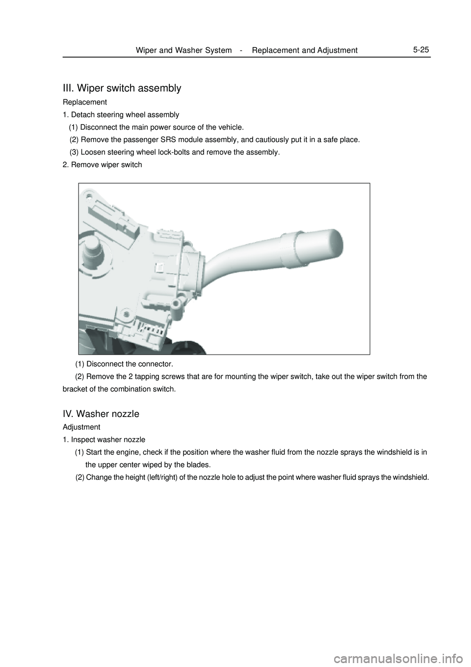
III. Wiper switch assemblyReplacement
1. Detach steering wheel assembly
(1) Disconnect the main power source of the vehicle.
(2) Remove the passenger SRS module assembly, and cautiously put it in a safe place.
(3) Loosen steering wheel lock-bolts and remove the assembly.
2. Remove wiper switch (1) Disconnect the connector.
(2) Remove the 2 tapping screws that are for mounting the wiper switch, take out the wiper switch from the
bracket of the combination switch.IV. Washer nozzleAdjustment
1. Inspect washer nozzle
(1) Start the engine, check if the position where the washer fluid from the nozzle sprays the windshield is in
the upper center wiped by the blades.
(2) Change the height (left/right) of the nozzle hole to adjust the point where washer fluid sprays the windshield.Wiper and Washer System -Replacement and Adjustment5-25
Page 222 of 416

Section 4 Front Fog Lamp ReplacementI. Removal1. Remove front bumper. (see bumper replacement)
2. Remove electrical connector.
3. Remove fixed bolt (as shown in the figure).
4. Remove front foglight assembly.II. Installation1. Install front foglight assembly.
2. Mount fixed bolt.
3. Mount electrical connector.
4. Mount front bumper.
5. Adjust vehicle state.
6. Adjust front foglight beam.III. Replacement of front head light bulb Remove dust shield by rotating anticlockwise
Pull out bulb plug
Press and loosen steel wire clip
Pull out lamp holder, take off bulb
Replace bulbLight System -Front Fog Lamp Replacement5-351-Turn light dust shield
2-Low beam dust shield
3-High beam, front position lamp dust shieldIII. Replacement of front foglight bulb1. Press and rotate anticlockwise, take off dust hood
2. Take out bulb
3. Replace bulbIV. Adjustment of front foglight beam1. Adjust tire pressure in standard value
2. Start up engine
3. Turn on foglight switch
4. Adjust foglight beam turn screw to adjust foglight beam in the vertical direction.
Description:
Turn screwdriver anticlockwise to make beam upward, or turn screwdriver clockwise to make it downward.
Page 223 of 416

Section 6 High-mounted Stop light ReplacementDisconnect the connector.
Remove the High mounted stop lamp in direction 1 and 2. (as shown
above in the illustration)I. Removal1. Remove trunk weather strip and trim.
2. Remove 3 installation nuts (as shown in the figure).
3. Remove rear combination light electrical connector.
4. Pull out rear combination light assembly towards vehicle backside.II. Installation1. Mount rear combination light, mount 3 installation nuts.
2. Mount electrical connector.
3. Mount trunk trim.
4. Mount weatherstrip.III. Replacement of rear combination light bulb1. Take off seal ring
2. Turn lamp holder anticlockwise, take off lamp holder
3. Take off bulb, replace bulbSection 5 Rear Combination Lamp ReplacementRear
shelf
High-mount stoplightlamp
holderLight System -Rear Combination Lamp Replacement/High-mounted Stop light Replacement5-36
Page 225 of 416

Wave band LF MF HF VHF
Radio wave AM FM
Modulation Amplitude modulation Frequency modulationFrequency 30KHZ 300KHZ 3MHZ 30MHZ 300MHZ
2. Area coverage
Scope of AM and FM broadcasting coverage area differs greatly.
Sometimes although AM broadcast may be received clearly, FM
binaural broadcasting cannot be received. Not only listening zone of
FM binaural broadcasting is small, but also static noise or other
cacophony (noise) tends to occur.
3. Receiving problem
Notes:
Besides static noise problem, there is also interference, multiplex
and attenuation. These problems are not caused by electric cacophony,
but the problem of radio wave itself.
(1) Interference
Besides static noise problem, AM broadcast tends to receive
other types of noise, especially at night. This is because ionosphere
reflects AM radio wave at night, these interference electric waves
interfere with signals from the same signal source while entering into
vehicle antenna directly, this kind of noise is called "interference".
(2) Multiplex
Noise caused by radio wave reflected from barrier is called
"multiplex". When radio signal emitted by broadcast antenna is
reflected by high buildings or high mountains, and disturbs directly
received other signals, multiplex phenomenon occurs.
(3) Attenuation
Since its frequency is higher than AM, FM wave is more easily
reflected by high buildings or high mountains. Therefore, FM signal
often disappears gradually, or when vehicle is blocked by barrier, it
cannot receive any signal, such phenomenon is called "attenuation".Audio System -Audio System Description5-38Chapter 5 Audio SystemSection 1 Audio System DescriptionDescription:
1. Radio wave band
Wave bands used in radiobroadcast are as follows:
LF: low frequency MF: medium frequency HF: high frequency VHF: very high frequencyFM (stereo)
FM (non-stereo)
AMInterference
IonosphereMultiplexAttenuation
Page 241 of 416

Chapter 6 SRS (Supplemental Restraint System)Section 1 SRS-General InformationI. Precaution for service For safe reasons, read the following precaution before starting any operation.
1. When servicing the SRS, correct sequence and items are described in the following chapter.
2. Instruments and special tools recommended in this chapter shall be used for operation.
3. When servicing the following components, replace them with the new ones if there is a failure.
(1) SRS ECU
(2) Clock Spring Module
(3) Driver Airbag Module
(4) Passenger Airbag Assembly
(5) Front Seat Belt Pretensioner
4. If there is any abnormality in the wire harness of the SRS, replace it with a new one. Correct or replace the
abnormal wire harness in accordance with Table 1.pin1 pin15
pin29
pin16SRS (Supplemental Restraint System)-SRS-General Information5-54No Designation
1 Belt-pretensioner, Driver, Low
2 Belt-pretensioner, Driver, High
3 Belt-pretensioner, Passenger, High
4 Belt-pretensioner, Passenger, Low
5 IGN
6 GND
7WL
9K
10 DAB Hi
11 DAB Lo
13 (Optional) PAB Hi
14 (Optional) PAB Lo
27 Crash Output ECU Terminal Description5. Servicing operation shall be carried out 60s after the negative(-) terminal cable is disconnected from the battery.
In addition, the disconnected negative (-) terminal cable shall be protected with insulating tape for insulation. In