GEELY MK 2008 Workshop Manual
Manufacturer: GEELY, Model Year: 2008, Model line: MK, Model: GEELY MK 2008Pages: 416, PDF Size: 25.19 MB
Page 201 of 416
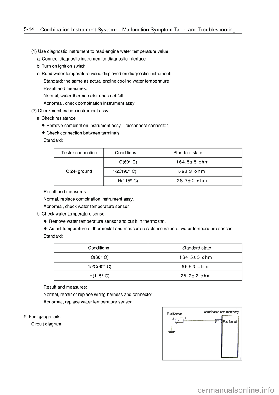
Tester connection Conditions Standard state
C(60°C)164.5±5 ohm
C 24- ground 1/2C(90°C)56±3 ohm
H(115°C)28.7±2 ohmConditions Standard state
C(60°C)164.5±5 ohm
1/2C(90°C)56±3 ohm
H(115°C)28.7±2 ohm5-14 (1) Use diagnostic instrument to read engine water temperature value
a. Connect diagnostic instrument to diagnostic interface
b. Turn on ignition switch
c. Read water temperature value displayed on diagnostic instrument
Standard: the same as actual engine cooling water temperature
Result and measures:
Normal, water thermometer does not fail
Abnormal, check combination instrument assy.
(2) Check combination instrument assy.
a. Check resistance
Remove combination instrument assy. , disconnect connector.
Check connection between terminals
Standard:
Result and measures:
Normal, replace combination instrument assy.
Abnormal, check water temperature sensor
b. Check water temperature sensor
Remove water temperature sensor and put it in thermostat.
Adjust temperature of thermostat and measure resistance value of water temperature sensor
Standard:
Result and measures:
Normal, repair or replace wiring harness and connector
Abnormal, replace water temperature sensor
5. Fuel gauge fails
Circuit diagramCombination Instrument System -Malfunction Symptom Table and Troubleshooting combination instrument assy
Fuel Sensor
Fuel Signal
Page 202 of 416
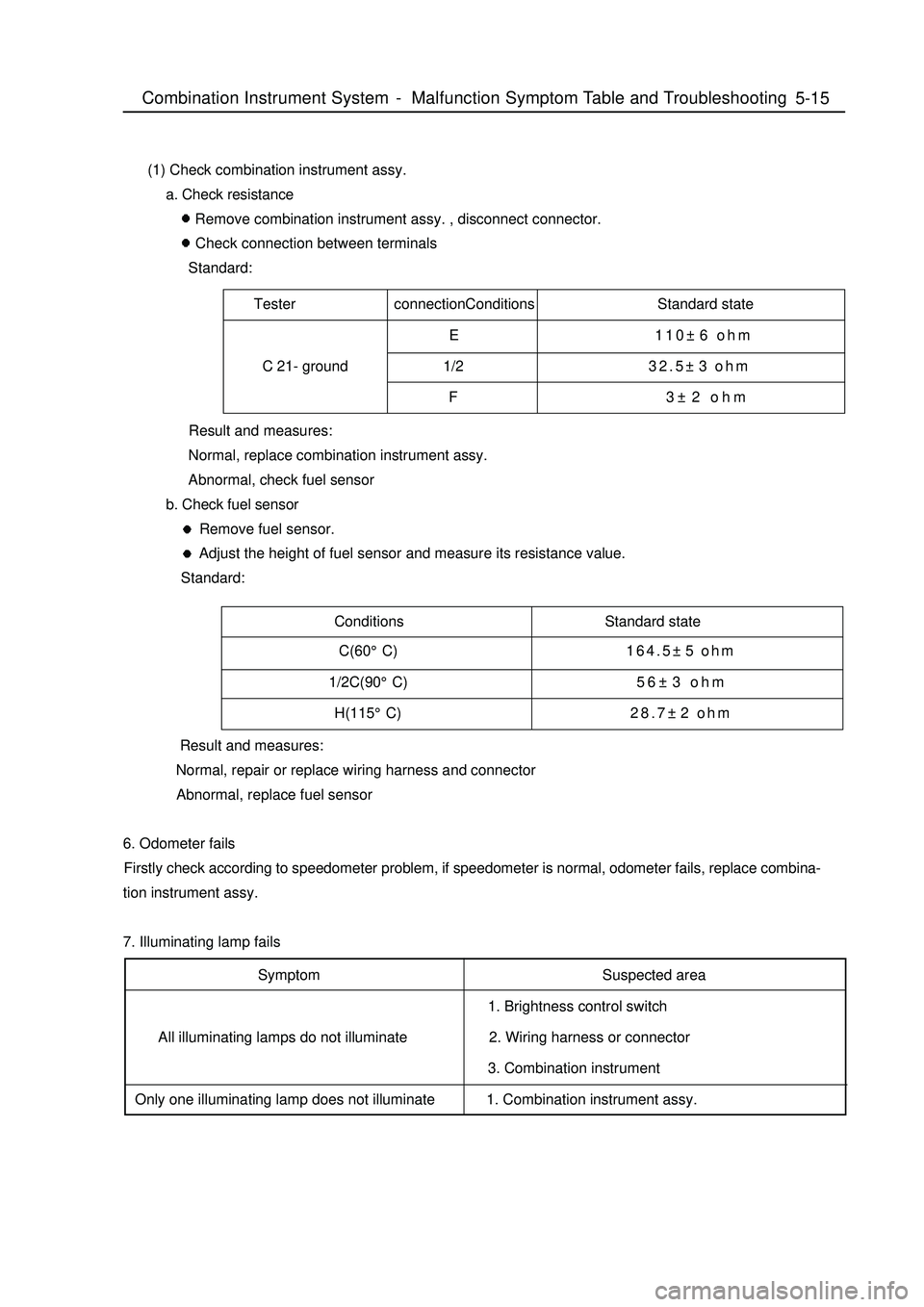
Tester connectionConditions Standard state
E 110±6 ohm
C 21- ground 1/232.5±3 ohm
F 3±2 ohmConditions Standard state5-15 (1) Check combination instrument assy.
a. Check resistance
Remove combination instrument assy. , disconnect connector.
Check connection between terminals
Standard:
Result and measures:
Normal, replace combination instrument assy.
Abnormal, check fuel sensor
b. Check fuel sensor
Remove fuel sensor.
Adjust the height of fuel sensor and measure its resistance value.
Standard:
Result and measures:
Normal, repair or replace wiring harness and connector
Abnormal, replace fuel sensor
6. Odometer fails
Firstly check according to speedometer problem, if speedometer is normal, odometer fails, replace combina-
tion instrument assy.
7. Illuminating lamp fails
Symptom
All illuminating lamps do not illuminate
Only one illuminating lamp does not illuminateSuspected area
1. Brightness control switch
2. Wiring harness or connector
3. Combination instrument
1. Combination instrument assy.Combination Instrument System -Malfunction Symptom Table and Troubleshooting C(60°C)164.5±5 ohm
1/2C(90°C)56±3 ohm
H(115°C)28.7±2 ohm
Page 203 of 416

Suspected area
1. Wiring harness or connector
2. ECM
3. Combination instrument assy.
1. Wiring harness or connector
2. Alternator
3. Combination instrument assy.
1. Wiring harness or connector
2. Manual brake switch
3. Combination instrument assy.
1. Wiring harness or connector
2. Brake fluid level switch
3. Combination instrument assy.
1. Wiring harness or connector
2. ABS ECU or ABS warning lamp driving module
3. Combination instrument assy.
1. Wiring harness or connector
2. Airbag ECU controller
3. Combination instrument assy.
1. Wiring harness or connector
2. Airbag ECU controller
3. Combination instrument assy.
1. Wiring harness or connector
2. Front head light dimmer switch
3. Combination instrument assy.
1. Wiring harness or connector
2. Front head light dimmer switch
3. Combination instrument assy.
1. Wiring harness or connector
2. Rear defrost switch
3. Combination instrument assy. 8. Warning lamp fails
Symptom
Check that engine warning lamp does not
illuminate
Charge warning lamp does not illuminate
Park braking warning lamp does not
illuminate
Brake failure warning lamp does not
illuminate
ABS warning lamp does not illuminate
SRS warning lamp does not illuminate
Passenger's airbag indicator lamp does
not illuminate
High beam indicator lamp does not
illuminate
Rear foglight indicator lamp does not
illuminate
Rear defrost indicator lamp does not
illuminate5-16Combination Instrument System -Malfunction Symptom Table and Troubleshooting
Page 204 of 416

5-17Suspected area
1. Harness or connector.
2. Front fog switch
3. Combination instrument assy.
1. Wiring harness or connector
2. Cuolant temperature sensor
3. Combination instrument assy.
1. Wiring harness or connector
2. Safety belt buckle switch
3. Combination instrument assy. Symptom
Front fog switch lamp does not illuminate
Water temperature warning indicator lamp
does not illuminate
Safety belt warning indicator lamp does
not illuminateCombination Instrument System -Malfunction Symptom Table and Troubleshooting
Page 205 of 416
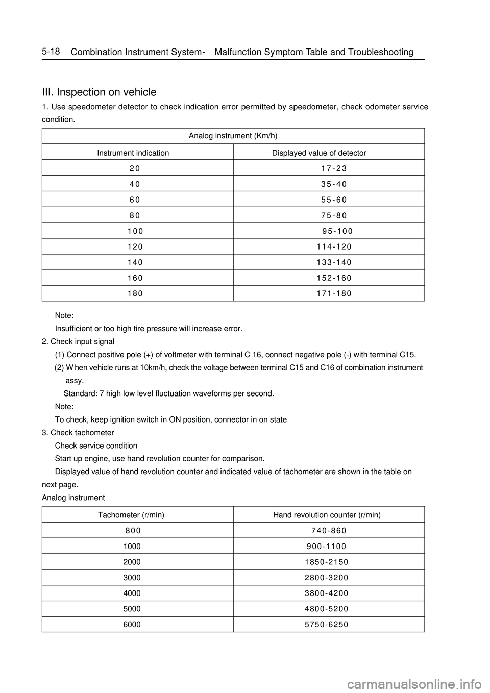
Analog instrument (Km/h)
Instrument indication Displayed value of detector
20 17-23
40 35-40
60 55-60
80 75-80
100 95-100
120 114-120
140 133-140
160 152-160
180 171-180
Tachometer (r/min) Hand revolution counter (r/min)
800 740-860
1000900-1100
20001850-2150
30002800-3200
40003800-4200
50004800-5200
60005750-6250 Note:
Insufficient or too high tire pressure will increase error.
2. Check input signal
(1) Connect positive pole (+) of voltmeter with terminal C 16, connect negative pole (-) with terminal C15.
(2) When vehicle runs at 10km/h, check the voltage between terminal C15 and C16 of combination instrument
assy.
Standard: 7 high low level fluctuation waveforms per second.
Note:
To check, keep ignition switch in ON position, connector in on state
3. Check tachometer
Check service condition
Start up engine, use hand revolution counter for comparison.
Displayed value of hand revolution counter and indicated value of tachometer are shown in the table on
next page.
Analog instrumentIII. Inspection on vehicle1. Use speedometer detector to check indication error permitted by speedometer, check odometer service
condition.5-18Combination Instrument System -Malfunction Symptom Table and Troubleshooting
Page 206 of 416
Note:
To measure, disconnect the connector.
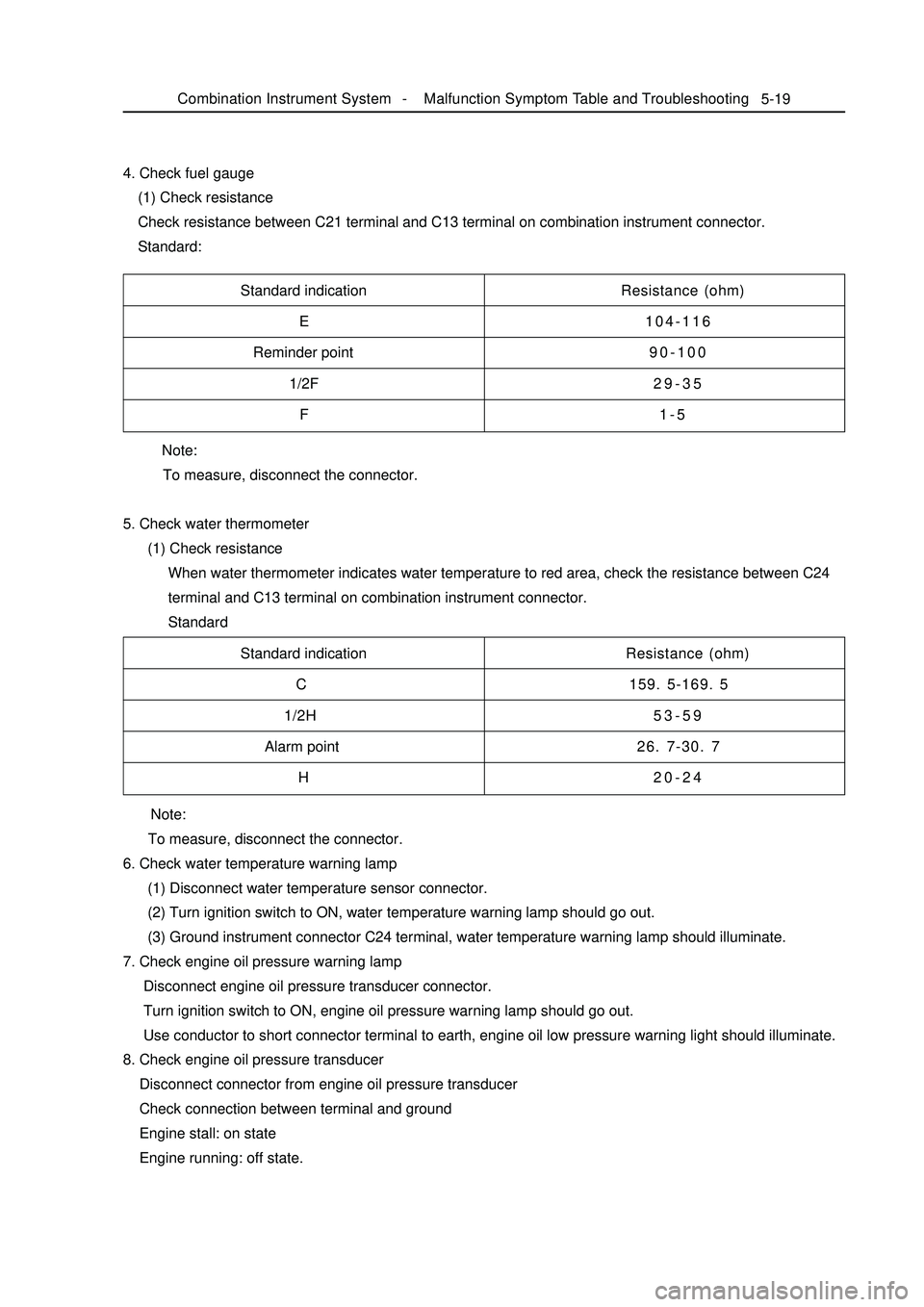
5. Check water thermometer
(1) Check resistance
When water thermometer indicates water temperature to red area, check the resistance between C24
terminal and C13 terminal on combination instrument connector.
Standard 4. Check fuel gauge
(1) Check resistance
Check resistance between C21 terminal and C13 terminal on combination instrument connector.
Standard:5-19Standard indication
E
Reminder point
1/2F
FResistance (ohm)
104-116
90-100
29-35
1-5
Standard indication
C
1/2H
Alarm point
HResistance (ohm)
159. 5-169. 5
53-59
26. 7-30. 7
20-24
Note:
To measure, disconnect the connector.
6. Check water temperature warning lamp
(1) Disconnect water temperature sensor connector.
(2) Turn ignition switch to ON, water temperature warning lamp should go out.
(3) Ground instrument connector C24 terminal, water temperature warning lamp should illuminate.
7. Check engine oil pressure warning lamp
Disconnect engine oil pressure transducer connector.
Turn ignition switch to ON, engine oil pressure warning lamp should go out.
Use conductor to short connector terminal to earth, engine oil low pressure warning light should illuminate.
8. Check engine oil pressure transducer
Disconnect connector from engine oil pressure transducer
Check connection between terminal and ground
Engine stall: on state
Engine running: off state.Combination Instrument System -Malfunction Symptom Table and Troubleshooting
Page 207 of 416

5-209. Check park warning lamp
(1) Disconnect connector from park switch
(2) Turn ignition switch to ON, park brake warning lamp should go out.
(3) Use conductor to short connector terminal to ground, park brake warning lamp should illuminate.
10. Check park switch
(1) Disconnect connector from park switch
(2) Pull up manual brake, check whether its terminal is connected with ground
Pull up manual brake: on
Manual brake release: off
11. Brake fluid level warning lamp
(1) Disconnect connector from brake fluid level sensor
(2) Turn ignition switch to ON, brake fluid level warning lamp should go out.
(3) Use conductor to connect its connector terminal wiring harness terminals directly, brake fluid level
warning lamp should illuminate.
12. Check brake fluid level warning switch
(1) Remove tank cap
(2) Disconnect connector from tank
(3) Check whether terminals are connected.
Floater on top: off
(4) Use sucker to suck out liquid from tank
(5) Check whether terminals are connected.
Floater down: on state
(6) Pour liquid back into tank
13. Rear defrost indicator lamp
(1) Turn ignition switch to ON, and start up engine
(2) Push down defrost switch, now rear defrost indicator lamp should illuminate
(3) Turn ignition switch to OFF, rear defrost indicator lamp should go out
14. Rear foglight indicator lamp
When rear foglight illuminates, rear foglight indicator lamp should illuminate, now A5 terminal should be high
potential.
15. Safety belt warning indicator lamp
(1) Disconnect safety belt switch connector from driver side, now safety belt warning indicator lamp should
go out.
(2) Short connector terminal to ground, safety belt warning indicator lamp should illuminate.Combination Instrument System -Malfunction Symptom Table and Troubleshooting
Page 208 of 416

Chapter 3 Wiper and Washer SystemSection 1 Wiper and Washer System Inspection5-21Remark:
The table below can help you find the causes of malfunction. These figures show the most possible
malfunctions in order of priority. Inspect each part in the order given. If necessary, repair or replace these parts.
Symptom
Front wiper does not work.
Front wiper in intermittent shift does not work.
Front washer motor does not work
When the washer switch is placed ON, front
wiper does not work
Washer fluid dose not jet out
1. When the washer switch places on OFF, wiper
blade can not return, or stay in a wrong place.
2. The wiper blade scratches the bodySuspected Area
1. Wiper fuse
2. Wiper switch assembly
3. Harness
1. Wiper switch assembly
2. Wiper motor assembly
3. Harness
4. Central controller
1. Wiper fuse
2. Wiper switch assembly
3. Wiper motor assembly
4. Harness
1. Wiper switch assembly
2. Wiper motor assembly
3. Harness
4. Central controller
1. Washer hose and nozzle
1.Wiper motor assembly (The position of wiper arm)II. Trouble shooting1. Check work of washer pump
(1) Install washer pump on tank system, pour cleaning fluid into
the tank.
(2) Disconnect connector of washer pump.
(3) As shown in the figure below, connect No. 1 terminal of
washer pump with positive pole (+) of storage battery; con
nect No. 2 terminal with negative pole (-) of storage battery.
Check whether cleaning fluid flows from tank.
(4) If there is no outflow, replace washer pump.Wiper and Washer System -Wiper and Washer System Inspection
Page 209 of 416

ON(10-14V)
OFF(OV)Wiper and Washer System -Wiper and Washer System Inspection5-222. Wiper, washer switch assembly
(1) Channel check
Check whether terminals on connector are on.
Standard:
Front wiper switch
Switch motion Testing terminal Specified state
MIST8-10 ON
OFF 3-10 ON
INT 8-6 3-10 ON
LO 8-10 ON
HI 8-11 ON
Note: No. 2. and No. 4 terminals are always ON.
Front washer switch
Switch motion Testing terminal Specified state
OFF OFF
ON 8-7 ON
If in OFF state, replace switch
(2) Check work (washer switch)
a. Turn washer switch to OFF position.
b. Connect positive pole (+) of storage battery with No. 8
terminal of connector,connect negative pole (-) with No.
2 terminal of wiper connector.Turn washer switch to ON
and OFF,measure the voltage between No. 8 terminal and
wiper motor connector No. 2 terminal.
Standard: see the figure in the left
If it doest not meet stipulation, replace the switch.
3. Wiper motor assembly
(1) Low speed gear inspection
Connect positive pole (+) of storage battery and No. 3
terminal of connector, connect negative pole (-) and No.
2 No. 2 terminal (E) of connector, check motor speed at
low speed gear.
If it does not meet stipulation, replace the motor.
Page 210 of 416
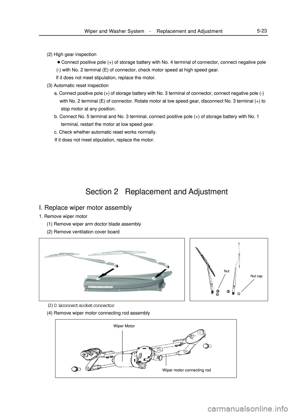
Section 2 Replacement and AdjustmentI. Replace wiper motor assembly1. Remove wiper motor
(1) Remove wiper arm doctor blade assembly
(2) Remove ventilation cover board
(3) Disconnect socket connector
(4) Remove wiper motor connecting rod assemblyNut capNutWiper MotorWiper motor connecting rodWiper and Washer System -Replacement and Adjustment5-23 (2) High gear inspection
Connect positive pole (+) of storage battery with No. 4 terminal of connector, connect negative pole
(-) with No. 2 terminal (E) of connector, check motor speed at high speed gear.
If it does not meet stipulation, replace the motor.
(3) Automatic reset inspection
a. Connect positive pole (+) of storage battery with No. 3 terminal of connector, connect negative pole (-)
with No. 2 terminal (E) of connector. Rotate motor at low speed gear, disconnect No. 3 terminal (+) to
stop motor at any position.
b. Connect No. 5 terminal and No. 3 terminal, connect positive pole (+) of storage battery with No. 1
terminal, restart the motor at low speed gear.
c. Check whether automatic reset works normally.
If it does not meet stipulation, replace the motor.