air condition GEELY MK 2008 Service Manual
[x] Cancel search | Manufacturer: GEELY, Model Year: 2008, Model line: MK, Model: GEELY MK 2008Pages: 416, PDF Size: 25.19 MB
Page 263 of 416

Condition/ circuit Tester connection Specification
OFF OFF
LO E D1 ON
ML E D1 D2 ON
MH E D1 D4 ON
HI E D1 D5 ONBlower switch connector unitD2 D4 D5
D1 D6 E4. Integrated control panel assembly
(a) Check connection of blower switch. If connection does not conform to specification, replace integrated control panel assembly.
(b) Check lighting operation
Connect positive wire of storage battery to terminal D6, negative wire to terminal E, then check whether
illuminating lamp illuminates. If bulb does not illuminate, replace the bulb.
(c) Check connection of air conditioning switch
As shown in the table, check connection of terminal when switch is pressedA/C switch connectorTester connection Specification
2 5 ON If connection does not conform to specification, replace air
conditioning switch.
(d) Check indicator work
Connect positive wire of storage battery to terminal 1, negative
wire to terminal 3, then check whether illuminating lamp
illuminates.
If connection does not conform to specification, replace
integrated control panel assembly.
4. Blower adjustment resistor
(a) Measure resistance between terminals, as shown in the table
Tester connection Specification
1-2 About 0. 38 Ohm
2-3 About 1. 47 Ohm
1-4 About 2. 71 OhmSpeed regulating resistance connector unit If resistance does not conform to specification, replace blower
resistance.
5. Blower assembly
(a) Connect positive wire of storage battery to terminal 2, negative
wire to terminal 1, check work smoothness of motor.
If work does not conform to specification, replace blower
assembly5-76Air Conditioning System -General Information
Page 264 of 416

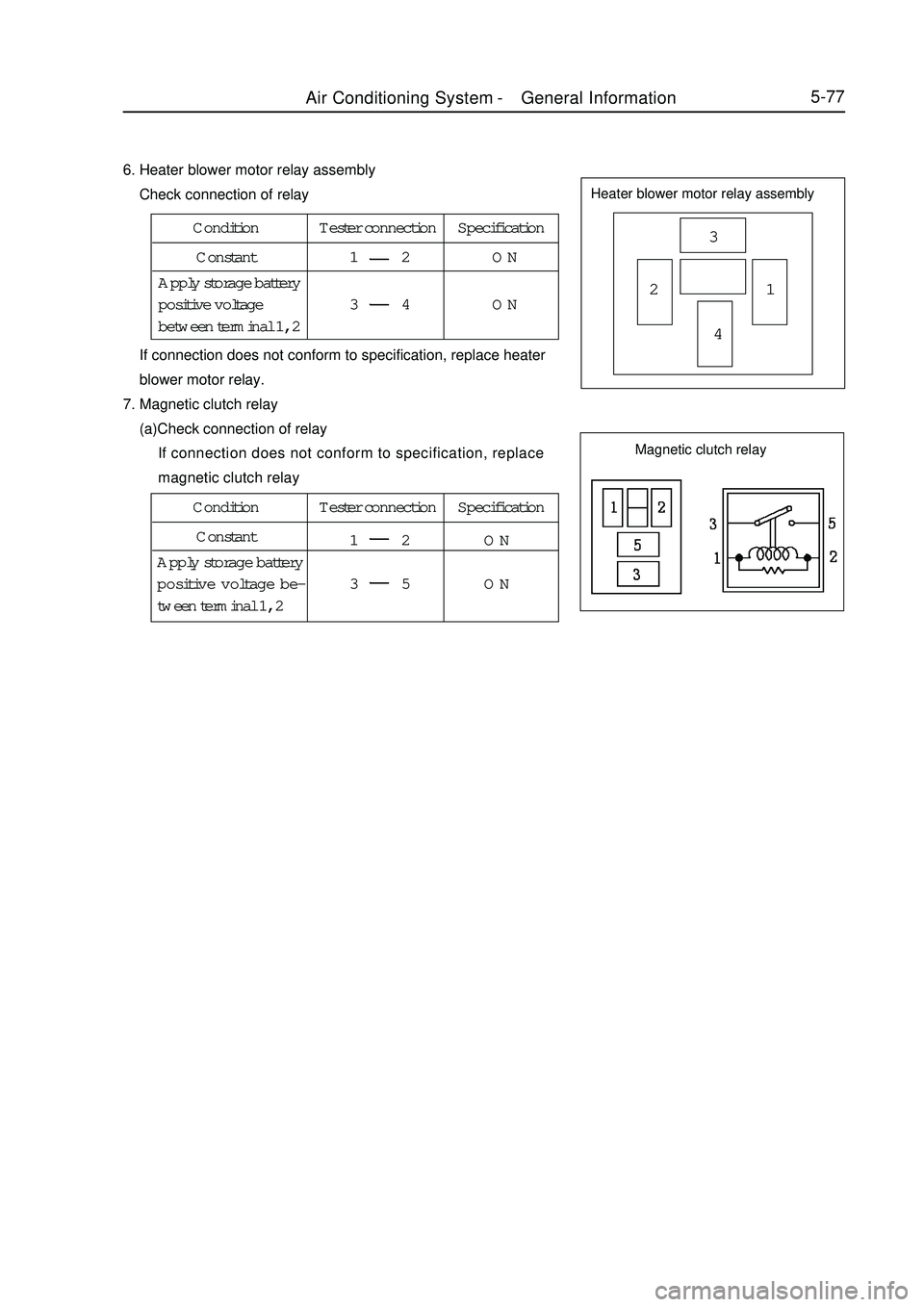
5-776. Heater blower motor relay assembly
Check connection of relayHeater blower motor relay assembly3
21
4 If connection does not conform to specification, replace heater
blower motor relay.
7. Magnetic clutch relay
(a)Check connection of relay
If connection does not conform to specification, replace
magnetic clutch relayCondition Tester connection Specification
Constant1 2 ON
3 4 ON Apply storage battery
positive voltage
between terminal 1, 2Condition Tester connection Specification
Constant
1 2 ON
3 5 ON Apply storage battery
positive voltage be-
tween terminal 1, 2Magnetic clutch relayAir Conditioning System -General Information
Page 265 of 416

Section 2 RefrigerantRefrigerant inspection1. Check refrigerant quantity
(a) Observe sight glass on refrigerating liquid pipe.
Test condition:
Engine speed: 1500 rpm
Blower speed control switch: HI "high "
Air conditioning switch: switch on
Temperature setting: maximum refrigeration
Refrigeration runs for 5 minutes
Open door
*: If refrigerating capacity is sufficient, environmental temperature is higher than normal condition, bubble
in sight glass may be deemed as normal.Symptom Refrigerant quantity Correct treatment2. Use manifold meter to check refrigerant pressure
( a ) This method is to utilize installed instrument to determine
where the fault is. Use manifold pressure meter reading to evaluate
fault condition.
Test condition:
Switch sets temperature of cyclical air inlet: 30-35°C
Engine speed: 1500 rpm
Blower speed control switch: high
Temperature control panel: refrigeration5-78With foam
Without foam
No temperature difference be-
tween input and output of
compressor
There is considerable tem-
perature difference between
compressor input and output
After air conditioner is turned
off, refrigerant should be
cleared immediately
After air conditioner is turned
off, refrigerant foams
immediately, then clears 1
2
3
4
5
6Insufficient *
Empty, insufficient or beyond
Empty or nearly full
Proper or beyond
Excess
Appropriate quantity1. Check gas leakage, repair if necessary
2. Add refrigerant until foam disappears
Refer to 3 and 4
1. Use detector to check gas leakage,
repair if necessary
2. Add refrigerant until foam disappears.
Refer to 5 and 6
1. Discharge refrigerant
2. Eliminate air, add appropriate quantity
of pure refrigerantSight glassAir Conditioning System -
Refrigerant
Page 266 of 416

5-79 Air conditioning switch: switch on
So door is completely open
(1) Refrigerating system meter reading during normal work:
Low pressure side: 0. 15-0. 25MPa
High pressure side: 1. 37-1. 57MPa
(2) System contains moistureSymptom Possible cause Diagnosis Correct treatment 1. During work, pressure
on low pressure side some-
times becomes vacuum
2.Intermittent refrigeration,
finally no refrigerationMoisture in the system
freezes at orifice of expan-
sion valve, circulation
suspends, but system re-
stores to normal after ice
thaws1. Drying agent is in satu-
rated state
2.System moisture
freezes at orifice of ex-
pansion valve, obstructs
refrigerant circulation1. Replace stock solution dry-
ing agent
2. By drawing off air repeti-
tively to remove water vapor in
the system, fill in appropriate
quantity of new refrigerant Pressure gauge indication when there is moisture in the system (3) Poor coolingManifold pressure gauge indication in case of poor cooling1. Pressure on high, low
pressure side is a bit low
2. Successive bubble ap-
pears in glass window
3. Refrigeration efficiency
deterioratesRefrigerant leakage
occurs in refrigerat-
ing system1. System refriger-
ant is insufficient
2. Refrigerant leaks1. Use leak detector to check whether
there is gas leakage, repair if there is any.
2. Fill in appropriate quantity of refriger-
ant
3. Connect a pressure gauge, if pressure
is zero, repair leaking part, and vacuumize
the systemSymptom Possible cause Diagnosis Correct treatmentAir Conditioning System -Refrigerant
Page 267 of 416

(4) Poor refrigerant circulation1. Indicates vacuum on low pres-
sure side, indicates too low pres-
sure on high pressure side
2. There is dew or frost on pipe
before and after expansion valve
or stock solution drier1. Pressure on high, low pressure side is a bit low
2. Pipeline from stock solution drier to main set frosts
3. Refrigeration is insufficientDirt in refrigeration
drier obstructs flow
of refrigerantStock solution
drier does not
circulateReplace stock
solution drierManifold pressure gauge indication in case of poor refrigerant circulationaSystem con-
tains moisture
or dirt which
obstructs flow
of refrigerant
Expansion
valve failureRefrigerant
does not cir-
culate1. Check expansion valve
2. Use compressed air to eliminate dirt of expan-
sion valve, but it cannot be eliminated, replace
expansion valve.
3. Vacuumize and fill in appropriate quantity of
new refrigerant
4. Expansion valve leaks, replace expansion valve Manifold pressure gauge indication in case of no refrigerant circulationa (5) Refrigerant does not circulateAir Conditioning System -Refrigerant5-80Symptom Possible cause Diagnosis Correct treatment
SymptomPossible cause Diagnosis
Correct treatmentWhen there is too much refrigerant or heat dissipation of condenser is poor (6) Too much refrigerant or heat dissipation of radiator is poor
Page 268 of 416

Air Conditioning System -Refrigerant5-811. Too high pressure on the
high and low pressure side
2. Even with decreasing engine
speed, no bubble can be seen
through view glass
3. Refrigeration is insufficient1. Excessive refrigerant,
not utilizing the efficacy
of refrigerant
2. Poor heat dissipation
of condenser1.Excessive refrigerant is
circulating
2. Insufficient refrigera-
tion in condenser, block
of condenser radiator or
fan fault1. Clean condenser
2. Check operation of fan
motor
3.Check the amount of
refrigerant, and fill in proper
amount of refrigerant1. Pressure on high, low pressure side
is too high
2. Touch thesuction hose, it is hot
3. Bubble appears in glass window,
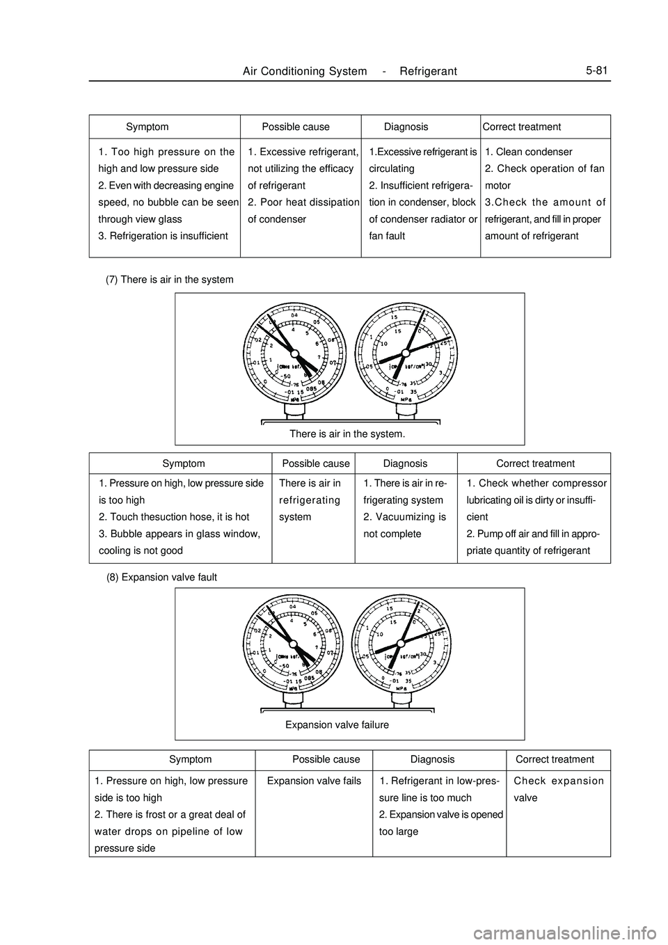
cooling is not goodThere is air in
refrigerating
system1. There is air in re-
frigerating system
2. Vacuumizing is
not complete1. Check whether compressor
lubricating oil is dirty or insuffi-
cient
2. Pump off air and fill in appro-
priate quantity of refrigerantThere is air in the system. (7) There is air in the system (8) Expansion valve fault1. Pressure on high, low pressure
side is too high
2. There is frost or a great deal of
water drops on pipeline of low
pressure sideRefrigerant in low-pres-
sure line is too much
2. Expansion valve is opened
too largeCheck expansion
valveExpansion valve failureSymptom Possible cause Diagnosis Correct treatment
Symptom Possible cause Diagnosis Correct treatment Symptom Possible cause Diagnosis Correct treatment
Expansion valve fails1.
Page 269 of 416

1 pressure is too high on low
pressure side, pressure on high-
pressure side is too low
2. Without cold airInside sealing of compressor
is poorCompressor fails, valve
leaks or is damaged.Repair or replace
compressorCompressor failure (9) Compressor poor compression faultDischarge and fill-up of refrigerantDischarge of refrigerant
In case of depletion, surrounding environment should always be
well-ventilated, do not approach open fire, otherwise toxic gas might
be generated.
(1) Firstly turn off meter valve high low manual valve, connect
pipeline according to the figure below, then adjust air conditioner to
maximum refrigeration operating condition, adjust engine speed to
1000 - 2000 r/min, run for 5 min. Circulate refrigerant and collect
residual oil in parts as far as possible into compressor.Symptom Possible cause Diagnosis Correct treatment (2) Loosen throttle, let engine restore to normal idle speed, turn off engine.
(3) Slowly open high voltage manual valve,cover a white towel on hose outlet,observe whether there is oil stain
on the towel, adjust flow of refrigerant.
(4) When high pressure gauge reading decreases to below 0. 35MPa, slowly open low pressure manual valve.
Close manual valve until reading of high low pressure gauge is zero.Fill-up of refrigerant (1) Use vacuum pump to vacuumize the system
During repair of refrigerating system, once refrigerating system is exposed to air or certain refrigerating
system part is to be replaced, automobile air conditioner must be vacuumized. So as to eliminate air and
water vapour in the system.
(2) Fill in R134 a
Standard: 420 ± 10 g (Dongfeng Painen System)
440 ± 20 g (Tianjing Sando System)Air Conditioning System -Refrigerant5-82Compressor
Gathering tank
Page 270 of 416

Air Conditioning System -A/C Operating Mechanism5-83Section 3 A/C Operating Mechanism1. Remove heater control and attachment assembly
(1) Remove three control knobs.
(2) Remove two screws and middle instrument board
subassembly.
(3) Loosen six lock catches, pull out heater control and attach
ment assembly
2. Remove the operation mechanism
(1) Loosen the fixed clip (air distributor) and remove the air mit
damper conrol cable.
(2) Loosen the fixed clip (air distributor) and remove air inlet
mode selector cable.:clip:clipClamp
Page 271 of 416

(3) Loosen the fixed clip (air distributor) and remove the adjust-
ment vent cable.
(4) Loosen 3 fasteners on the operation mechanism and remove
the operation mechanism assembly.
3.Remove the cable of the operation mechanism
(1) Loosen the fixed clip and remove air inlet mode selector cable.
(2) Loosen the fixed clip and remove the air mit damper conrol
cable.
(3) Loosen the fixed clip and remove the adjustment vent cable.
Notice: Do not twist the cable,otherwise the air conditianing
operation mechanism does not work normally.:clipAir Conditioning System -
A/C Operating Mechanism5-84Clamp
Page 272 of 416

Air Conditioning System -A/C Operating Mechanism5-855. Install the control mechanism assembly
(1) Replace the damaged part, installation is in the reverse order of removal.
(2) Notice:
When installing the warm and cold adjustment damper cable on the head unit of the air conditioner, set
the rocker arm connecting the cable to the maximum travel position of the damper for refrigeration, then
press the cable in the clamp. Do not twist the cable. Check that the temperature control knob on the
rotation panel can stop at both the maximum refrigeration and maximum heating positions and won't
resile.
When installing the inner and outer cycle damper cable on the head unit of the air conditioner, set the
rocker arm connecting the cable to the maximum travel position of the inner cycle, then press the cable
in the clamp. Do not twist the cable. Check that the air intake adjustment rod on the rotation panel can
stop at both the inner and outer cycle maximum positions and won't resile.
When installing the outlet vent adjustment damper cable on the head unit of the air conditioner, set the
rocker arm connecting the cable to the maximum travel position of face mode, then press the cable in
the clamp. Do not twist the cable. Check that the airflow selector knob on the rotation panel can stop
at both the face mode and defroster heating positions and won't resile.4. Remove the inner and outer cycle flipper
Unscrew the retaining buckle and the inner and outer cycle
flipper.Clamp