air condition GEELY MK 2008 Repair Manual
[x] Cancel search | Manufacturer: GEELY, Model Year: 2008, Model line: MK, Model: GEELY MK 2008Pages: 416, PDF Size: 25.19 MB
Page 273 of 416

Section 4 Heater, Ventilation and Air ConditioningComponent View INo. 2 coolant TankNo.1 coolant Pipe Dual Steel Wire Circlip
Exhaust Pipe Exhaust Pipe Seal
RingSeal Ring A/C Head Unit AssemblyAir Conditioning System -Heater, Ventilation and Air Conditioning5-86
Page 274 of 416

air inlet case
air screen
screen support
Type H expansion valve
evaporator core
thermistor blower with impellor
assembly
rear air outlet case lower caseupper caseheater core heater core
clipComponent View IIAir Conditioning System -Heater, Ventilation and Air Conditioning5-87
Page 275 of 416

Overhaul1. Drain the coolant (refer to Coolant for details).
2. Disconnect A/C pipeline assembly.
(1) Remove the bolt, disconnect A/C pipeline assembly
(2) Remove 2 O-rings form the A/C pipeline assembly.
Notice: O-ring is a non-reusable part.
3. Disconnect the water pipe assembly connecting the heater core.
Loosen the dual steel wire circlip, disconnect the water pipe
connecting the heater core.
4. Remove console assembly
Refer to Interior Trim: Removal of the Console Assembly
5. Remove central cross member assembly
(1) Unscrew the wire harness clip and screw.
(2) Remove the nut and bolt.
(3) Remove cross member assembly.
6. Remove A/C lower left and right air outlet pipe
(1) Unscrew the two clips, disconnect the A/C lower left air outlet
pipe.
(2) Unscrew the two clips, disconnect the A/C lower right air
outlet pipe.5-88clip clipclip
screw,nut and
boltAir Conditioning System ¡ª¡ªHeater, Ventilation and Air Conditioning
Page 276 of 416

5-897. Disconnect engine ECU
(1) Remove 3 bolts.
(2) Carefully disconnect the wire harness.
8. Remove A/C head unit assembly.
(1) Remove the clip attaching the console wire harness on the
A/C head unit body.
(2) Disconnect 3 connectors.
(3) Remove 2 bolts and 5 nuts, remove the A/C head unit
assembly
9. Remove heater core
(1) Loosen two clips, remove the air inlet case assembly.
(2) Remove the screw, clamp and heater core.
10. Remove A/C wire harness
disconnect the connector, remove the A/C wire harness.2 clipsAir Conditioning System -Heater, Ventilation and Air Conditioning
Page 277 of 416

5-9011. Remove adjustment resistor
remove 2 screws and blower adjustment resistor.
12. Remove blower motor with impellor assembly.
remove 3 screws and blower motor with impellor assembly.
13. Remove rear air outlet case
remove rear air outlet case after loosening the clip.
14. Remove Type H expansion valve
Use inner hex wrench of 5.0mm to remove 2 bolts and type H
expansion.
15. Remove the thermistor on the evaporator
(1) Disconnect the mode damper drive arm.4 clipsAir Conditioning System -
Heater, Ventilation and Air Conditioning
Page 278 of 416

5-91 (2) Remove 12 screws and upper case assembly.
(3) Remove the thermistor from the evaporator.
16. Remove evaporator core assembly
(1) Remove evaporator core assembly from the lower case
assembly.
(2) Remove 2 O-rings from the evaporator core assembly.
Notice: O-ring is a non-reusable part.
17. Remove exhaust pipe
18. Installation
(1) Installation is in the reverse order of removal.
(2) O-ring is a non-reusable part and needs to be replace.Air Conditioning System -Heater, Ventilation and Air Conditioning
Page 279 of 416

Section 5 Layont of Air Conditioning HoseComponent View5-92Compressor Suction Hose
Dual Tube
ClipCompressor Exhaust Hose
Single-Tube Clip
Pressure Switch
Liquid Tube
High, Low Pressure Tube AssemblyAir Conditioning System -Layont of Air Conditioning Hose
Page 280 of 416

Section 6 Multi-wedge belt (Connecting Compressor and
Crankshaft Pulley)Replacement1. Remove multi-wedge belt
(1) Loosen nut A.
(2) Loosen bolt B, remove multi-wedge belt (A/C compressor to
crankshaft pulley)
2. Install multi-wedge belt
as shown in the illustration, temporarily install the multi-wedge
belt.
3. Adjust multi-wedge belt
(1) Tighten nut A
Torque: 25 N.m
(2) Adjust the belt tension by turning bolt B.
Belt Distortion:
New belt: 6.5 - 7.0mm
Old belt: 8.0- 9.0mm
Tip:
New belt means the belt used on the engine for less than 5
minutes.
Old belt means the belt used on the engine for more than 5
minutes.
Install the drive belt,check whether the belt fit the belt slot.
Use hand to confirm that the belt does not slide in the belt slot.
4. Tighten multi-wedge belt
Tighten bolt A
Torque: 39 N.m5-93nut Abolt B
nut Ablot B
Measuring
pointCorrectWrongAir Conditioning System -
Multi-wedge belt (Connecting Compressor and Crankshaft Pulley)
Page 281 of 416

Section 7 Compressor AssemblyComponent ViewReplacement1. System drains coolant (refer to Coolant for details)
2. Remove multi-wedge belt (refer to Multi-wedge Belt (A/C Compressor to Crankshaft Pulley for details)).Multi-Wedge Belt 4PK820Tensioner Assembly
Compressor Support
Hexagonal Bolt Spring and
Plate Washer Set (3 Pcs)Hexagonal Bolt
Spring and Plate
Washer Set
Compressor
Assembly
Hexagonal Bolt M8 x105Air Conditioning System -Compressor Assembly5-943. Disconnect the suction vent
(1) Remove the bolt, disconnect the suction vent.
(2) Remove the O-ring from the suction vent.
4. Disconnect the exhaust vent
(1) Remove the bolt, disconnect the exhaust vent.
(2) Remove the O-ring from the exhaust vent.
Notice:
Use vinyl tape seal all the interfaces of the disconnected
parts to avoid entry of water and foreign objects.
O ring is a non-reusable part.Suction port Discharge
port
Page 282 of 416

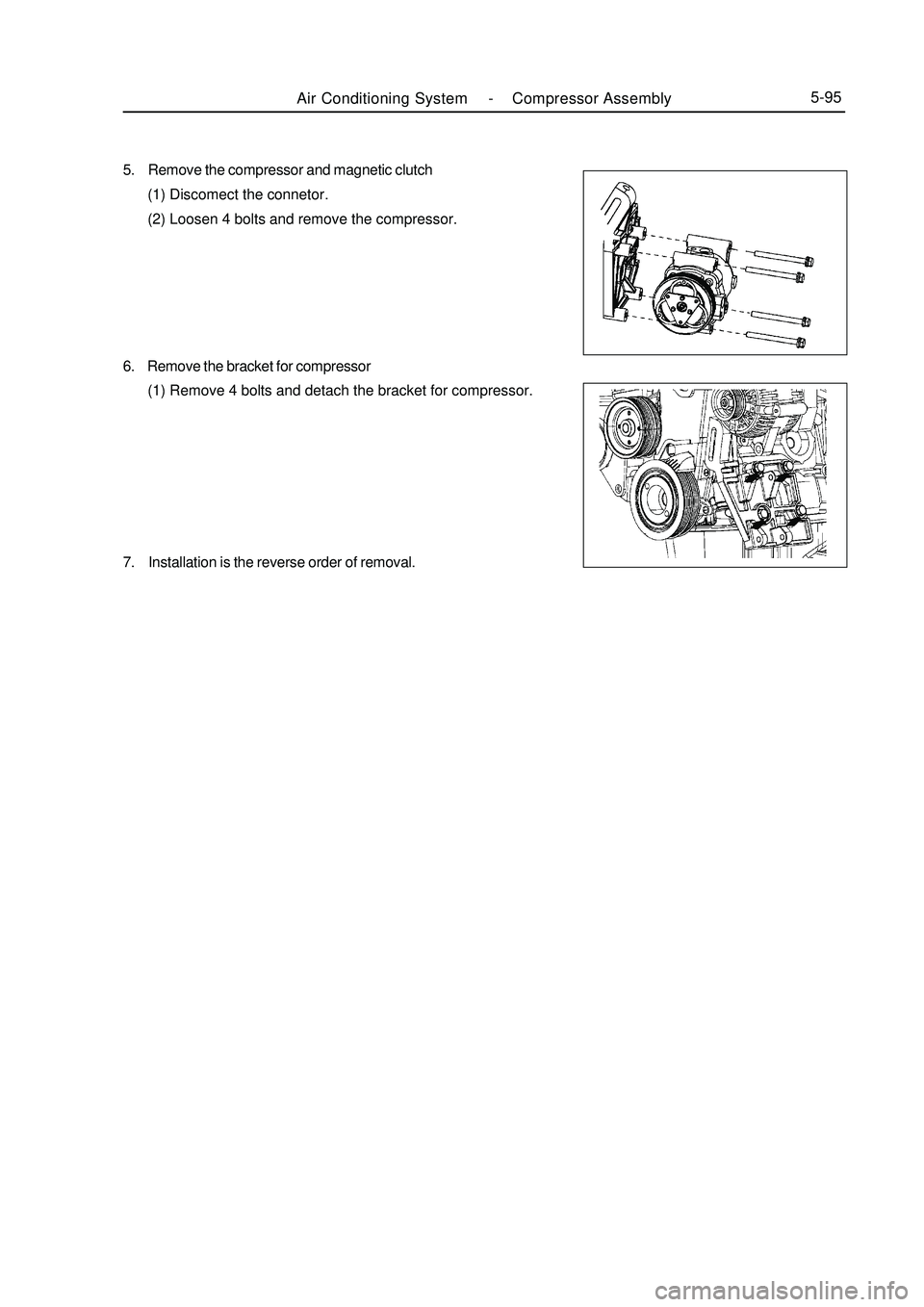
5. Remove the compressor and magnetic clutch
(1) Discomect the connetor.
(2) Loosen 4 bolts and remove the compressor.
6. Remove the bracket for compressor
(1) Remove 4 bolts and detach the bracket for compressor.
7. Installation is the reverse order of removal.Air Conditioning System -Compressor Assembly5-95