air condition GEELY MK 2008 Repair Manual
[x] Cancel search | Manufacturer: GEELY, Model Year: 2008, Model line: MK, Model: GEELY MK 2008Pages: 416, PDF Size: 25.19 MB
Page 283 of 416

Section 8 Condenser Fan Motor and Condenser AssemblyOn-board Inspection1. check condenser assembly
(1) if the radiator in the condenser is dirty, wash it with clean water and dry it with compressed air.
(2) if the radiator in the condenser is distorted, use the proper tool to correct it.
2. check the condenser for coolant leakage.
(1) use the leakage tester to check the connection area of the pipeline for leakage.
(2) If there is leakage, check the connector set bolt for tightening condition.Component Viewcondenser fan upper cushion
condenser fan
motor assembly
condenser as-
sembly
condenser lower
cushion condenser fan lower
cushioncondenser upper cushionAir Conditioning System -Condenser Fan Motor and Condenser Assembly5-96
Page 284 of 416

Overhaul1. Drain coolant (refer to Coolant for details).
2. Remove condenser fan motor assembly
(1) Disconnect condenser fan motor wire harness connector.
(2) Unscrew 1 bolt, remove condenser fan motor assembly.
3. Disconnect the liquid tube
(1) Remove the bolt, disconnect the liquid tube from the condenser.
(2) Remove the Oring from the liquid tube.
4. Disconnect the high and low pressure pipe assembly
(1) Remove the bolt, disconnect the high and low pressure tube
assembly from the condenser.
(2) Remove the Oring from the high and low pressure tube
assembly.
Notice: Use vinyl tape seal all the interfaces of the disconnected
parts to avoid entry of water and foreign objects.
5. Remove engine hood lock assembly
(1) remove the bolt, remove engine hood lock assemblyAir Conditioning System -Condenser Fan Motor and Condenser Assembly5-97
Page 285 of 416

Air Conditioning System -Condenser Fan Motor and Condenser Assembly5-986. Remove the centor backet for the radiator.
7. Remove the condenser body.
8. Change new O sealing ring and Installation is the reverse
order of removal.
Page 297 of 416

Note: this fault mode is only limited to the condition in which system may communicate with fault diagnosis
instrument (ABS ECU ABS ECU power supply is normal), and there is no fault code.MK-60 ABS system -ABS System Check5-110 After engine starts up, ABS warning lamp illuminates normally 2
[Description] Probably because ABS warning lamp driving module is
damaged or ABS warning lamp circuit is disconnected.Possible cause
ABS warning lamp driving
module is damaged
ABS warning lamp driving
module circuit is disconnected
ABS ECU is damagedCheck whether wire between
ECU and ABS warning lamp
driving module is disconnectedRepair wire harness Yes
NoCheck ABS warning lamp driv-
ing moduleReplace Abnormal
NormalReplace ABS ECU
Page 298 of 416

Whether sensor is installed correctlyInstall it correctly Yes Check sensor output voltageAbnormal
NormalCheck each sensorAbnormal
ReplaceNormal
Check gear ring of each sensorAbnormalNormalReplace
Check wheel bearing clearanceAbnormalNormalReplace or
repair
Check ABS ECU socket and
middle socket connectorAbnormalNormalReplace
socket
connector
Does fault recurNo
YesRefer to key point
for repair of oc-
casional faultRemove ABS ECU plug, check whether resis-
tance value between the following binding
posts conforms to standard value or not?
Standard value: 1.0-1.3K ohm¸
Shake sensor wiring harness and socket con-
nector while measuring
Left front: 44-45 Right front: 33-34
Left rear: 36-37 Right rear:42-43Repair wiring
harness or socket
connector NormalAbnormalReplace ABS ECUUse fault diagnosis instrument to
conduct diagnosis of hydraulic
control unitAbnormalReplace ABS HCUMK-60 ABS system -ABS System Check5-111ABS works abnormally 3
[Description] This issue is closely related to driver condition and
road surface condition, so it is not easy to conduct
fault diagnosis. However, if there is no fault code
memory, the following inspection may be conducted.Possible cause
Sensor is not installed properly
Sensor wiring harness has problem
Sensor is damaged
Gear ring is damaged
Sensor is attached with foreign
matter
Wheel bearing is damaged
ABS HCU (hydraulic pressure unit)
is damaged
ABS ECU (electric control unit) is
damaged
Page 299 of 416

Visually check whether Hydraulic coupler leaksScrew down pipe head as required Abnormal
Check worn condition of brake discReplace brake disc Abnormal
Check brake fluid level switchReplace brake fluid level switch Abnormal
Exhaust checkExhaust again Abnormal
Use fault diagnosis instrument hydraulic con-
trol unit for diagnosis
Check tightness of normally closed valve leakReplace HCU (hydraulic control unit) AbnormalUse fault diagnosis instrument hy-
draulic control unit for diagnostic
check of normally open valveReplace HCU(hydraulic control unit) AbnormalNormal
Normal
Normal
Normal
Normal
Use traditional method of non-ABS
vehicle to check booster and pedal
strokeMK-60 ABS system -ABS System Check5-112Travel of brake pedal is too long 4
[Description] Firstly visually check whether there is external leakage or
mechanical failure. Use exhaust method to check whether
there is air in the system. Use fault diagnosis instrument
hydraulic pressure unit functional testing to check whether
normally closed valve leaks.Possible cause
Brake fluid leaks
There is air in the system
Brake disc is worn severely
Brake fluid level switch
failsA very large force is needed to step on pedal 5
[Description] Use traditional method to check travel of booster and brake pedal.
Fault of normally open valve may be checked using fault diagnosis
instrument hydraulic pressure unit functional testingPossible cause
Booster has problem
Normally closed
valve has problem
Page 307 of 416

Fault symptom
Flameout, poor idle speedChapter 9 Engine EFI SystemI. Outline This system includes sensor that detects engine functioning. Engine ECU utilizes sensors installed at differ-
ent parts of engine to measure various working parameters of engine, accurately control oil injection quantity
according to control procedure set in engine electronic control unit, so engine could work in optimum mode
under various operating conditions, i. e. optimal power output, the most economical oil consumption, optimal
exhaust emissions. Engine ECU is capable of start up control, idle speed closed-loop control, air fuel ratio
closed-loop control, canister control, transient operation control, angle of ignition control, knocking control, air
conditioning control, coasting fuel cutoff and overspeed fuel cutoff control, ternary catalyst heating and protec-
tion control, system self-diagnosis etc.II. Inspection of control element1. Manifold intake pressure temperature sensor
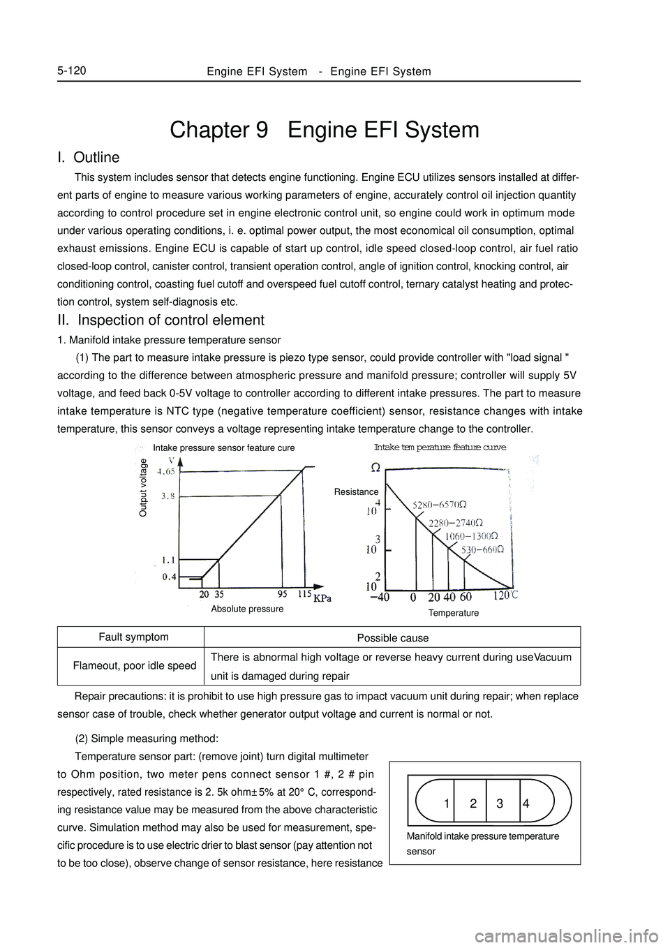
(1) The part to measure intake pressure is piezo type sensor, could provide controller with "load signal "
according to the difference between atmospheric pressure and manifold pressure; controller will supply 5V
voltage, and feed back 0-5V voltage to controller according to different intake pressures. The part to measure
intake temperature is NTC type (negative temperature coefficient) sensor, resistance changes with intake
temperature, this sensor conveys a voltage representing intake temperature change to the controller.
(2) Simple measuring method:
Temperature sensor part: (remove joint) turn digital multimeter
to Ohm position, two meter pens connect sensor 1 #, 2 # pinrespectively, rated resistance is 2. 5k ohm±5% at 20°C, correspond-ing resistance value may be measured from the above characteristic
curve. Simulation method may also be used for measurement, spe-
cific procedure is to use electric drier to blast sensor (pay attention not
to be too close), observe change of sensor resistance, here resistanceEngine EFI System-Engine EFI System5-120Possible cause
There is abnormal high voltage or reverse heavy current during useVacuum
unit is damaged during repair
Repair precautions: it is prohibit to use high pressure gas to impact vacuum unit during repair; when replace
sensor case of trouble, check whether generator output voltage and current is normal or not.1 2 3 4Manifold intake pressure temperature
sensor Intake pressure sensor feature cureIntake temperature feature curve
Output voltageAbsolute pressureTemperatureResistance
Page 308 of 416

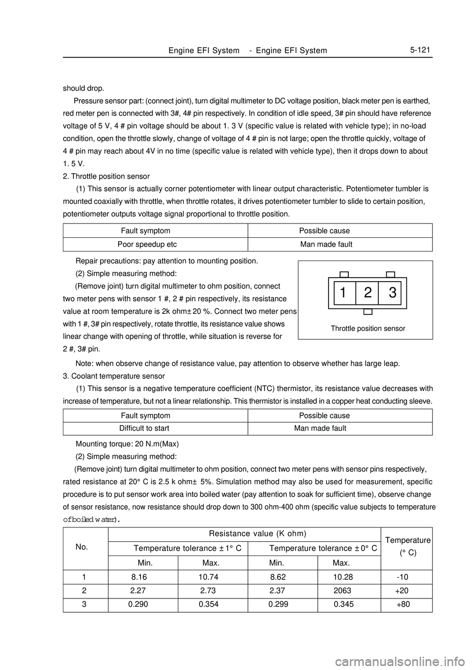
Fault symptom Possible cause
Poor speedup etc Man made fault1 2 3Throttle position sensorFault symptom Possible cause
Difficult to start Man made fault Repair precautions: pay attention to mounting position.
(2) Simple measuring method:
(Remove joint) turn digital multimeter to ohm position, connect
two meter pens with sensor 1 #, 2 # pin respectively, its resistance
value at room temperature is 2k ohm±20 %. Connect two meter pens
with 1 #, 3# pin respectively, rotate throttle, its resistance value shows
linear change with opening of throttle, while situation is reverse for
2 #, 3# pin.
Note: when observe change of resistance value, pay attention to observe whether has large leap.
3. Coolant temperature sensor
(1) This sensor is a negative temperature coefficient (NTC) thermistor, its resistance value decreases with
increase of temperature, but not a linear relationship. This thermistor is installed in a copper heat conducting sleeve.Engine EFI System-Engine EFI System5-121should drop.
Pressure sensor part: (connect joint), turn digital multimeter to DC voltage position, black meter pen is earthed,
red meter pen is connected with 3#, 4# pin respectively. In condition of idle speed, 3# pin should have reference
voltage of 5 V, 4 # pin voltage should be about 1. 3 V (specific value is related with vehicle type); in no-load
condition, open the throttle slowly, change of voltage of 4 # pin is not large; open the throttle quickly, voltage of
4 # pin may reach about 4V in no time (specific value is related with vehicle type), then it drops down to about
1. 5 V.
2. Throttle position sensor
(1) This sensor is actually corner potentiometer with linear output characteristic. Potentiometer tumbler is
mounted coaxially with throttle, when throttle rotates, it drives potentiometer tumbler to slide to certain position,
potentiometer outputs voltage signal proportional to throttle position. Mounting torque: 20 N.m(Max)
(2) Simple measuring method:
(Remove joint) turn digital multimeter to ohm position, connect two meter pens with sensor pins respectively,rated resistance at 20°C is 2.5 k ohm± 5%. Simulation method may also be used for measurement, specificprocedure is to put sensor work area into boiled water (pay attention to soak for sufficient time), observe changeof sensor resistance, now resistance should drop down to 300 ohm-400 ohm (specific value subjects to temperatureof boiled water).
Resistance value (K ohm)
No.Temperature
(°C) Temperature tolerance ±1°C Temperature tolerance ±0°C
Min. Max. Min. Max.
1 8.16 10.74 8.62 10.28 -10
2 2.27 2.73 2.37 2063 +20
3 0.290 0.354 0.299 0.345 +80
Page 309 of 416

4. Knocking sensor
(1) Knocking sensor is a vibration acceleration sensor. Mounted on engine cylinder body. Sensing element of
the sensor is a piezocrystal. Vibration of engine cylinder body is transferred to piezocrystal via mass block in the
sensor. Since pressure generated by vibration of mass block is applied to piezocrystal, it generates voltage on two
polar planes and turns vibration signal into voltage signal for output.5-122Symptom
Poor accelerationPossible cause
Various liquids, such as engine oil, cooling fluid, brake fluid, water etc
contact the sensor for a long time, which cause corrosion to the sensor. Mounting torque: 20 ± 5 N.M
Repair precautions: sensor must be fitted closely to cylinder body with its metal surface, any type of washer
is not permitted for installation. For wiring of sensor signal cables, note that do not let resonance occur to signal
cables, otherwise they might be broken. Energizing of high voltage between sensor 1 # and 2 # pins must be
avoided, otherwise piezoelectric element might be damaged.
(2) Simple measuring method:
(Remove joint) turn digital multimeter to ohm position, connect two meter pens with sensor 1 #, 2 # pin
respectively, its resistance value at room temperature should exceed 1M ohm. Turn digital multimeter to millivolt
position, use a hand hammer to tap near knocking sensor, now voltage signal output should be available.
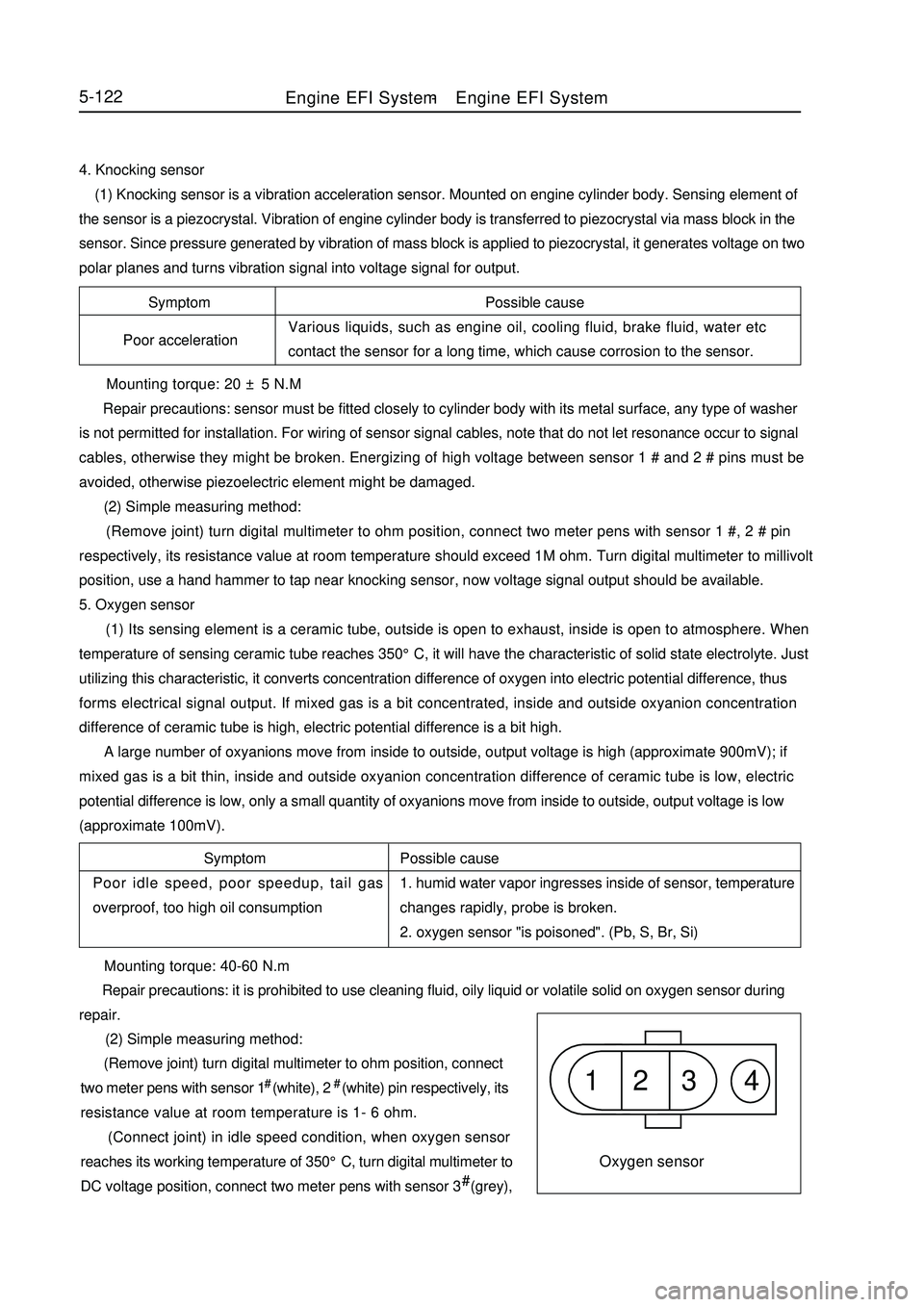
5. Oxygen sensor
(1) Its sensing element is a ceramic tube, outside is open to exhaust, inside is open to atmosphere. When
temperature of sensing ceramic tube reaches 350°C, it will have the characteristic of solid state electrolyte. Just
utilizing this characteristic, it converts concentration difference of oxygen into electric potential difference, thus
forms electrical signal output. If mixed gas is a bit concentrated, inside and outside oxyanion concentration
difference of ceramic tube is high, electric potential difference is a bit high.
A large number of oxyanions move from inside to outside, output voltage is high (approximate 900mV); if
mixed gas is a bit thin, inside and outside oxyanion concentration difference of ceramic tube is low, electric
potential difference is low, only a small quantity of oxyanions move from inside to outside, output voltage is low
(approximate 100mV).
Possible cause
1. humid water vapor ingresses inside of sensor, temperature
changes rapidly, probe is broken.
2. oxygen sensor "is poisoned". (Pb, S, Br, Si) Symptom
Poor idle speed, poor speedup, tail gas
overproof, too high oil consumption1 2 3 4Oxygen sensor Mounting torque: 40-60 N.m
Repair precautions: it is prohibited to use cleaning fluid, oily liquid or volatile solid on oxygen sensor during
repair.
(2) Simple measuring method:
(Remove joint) turn digital multimeter to ohm position, connect
two meter pens with sensor 1# (white), 2# (white) pin respectively, its
resistance value at room temperature is 1- 6 ohm.
(Connect joint) in idle speed condition, when oxygen sensor
reaches its working temperature of 350°C, turn digital multimeter to
DC voltage position, connect two meter pens with sensor 3# (grey),Engine EFI System-Engine EFI System
Page 312 of 416

Symptom
Poor idle speed, malfunction etc
Symptom
Fail to start5-125 Repair precautions:
1. according to engine requirement, electric fuel pumps with different flows are available, they have the same
appearance, mountable fuel pump may not be exactly suitable, during repair, part number of fuel pump used must
be consistent with original one, wrong replacement is not permitted;
2. in order to prevent fuel pump from damaging, please do not run it in dry state for a long time;
3. in case fuel pump needs to be replaced, please pay attention to clean fuel tank and pipeline and replace fuel
filter.
(2) Simple measuring method:
(Remove joint) turn digital multimeter to ohm position, connect two meter pens with fuel pump pins
respectively, measure internal resistance, it should not be zero or infinite (namely not in short circuit, open circuit
condition).
(Connect joint) connect fuel pressure gauge on sucker, start up engine, run the engine at idle speed, now fuel
pressure of engine should be about 260kPa; unplug fuel pressure regulator vacuum tube, now fuel pressure should
be about 300KPa.
11. Canister control valve
(1) Canister in fuel evaporation control system adsorbs oil vapor from oil tank until saturated. Electronic
control unit controls opening of canister control valve, fresh air and saturated fuel vapor in canister form
regeneration stream, which is led into engine intake pipe again. Electronic control unit changes duty ratio of pulsing
signal to canister control valve solenoid according to different operating conditions of engine, thus controls flow
of regeneration stream. In addition, this flow is also influenced by pressure difference at both ends.
Possible cause
Entering of foreign matter into valve inside results in
corrosion or poor leak tightness etc
Repair precautions:
1. To install, airflow direction must meet the specification;
2. when black granules inside valve body result in malfunction of control valve, and control valve needs to be
replaced, please check the condition of canister;
3. avoid water, oil etc liquids from entering valve as far as possible during repair;
4. in order to avoid transfer of solid-borne noise, it is recommended to install canister control valve suspending
on the hose or use soft rubber to fix.
(2) Simple measuring method:
(Remove joint) turn digital multimeter to ohm position, connect two meter pens with canister control valve pins
respectively, rated resistance at 20°C is 22 - 30 ohm.
12. Ignition coil
(1) When earthing channel of primary winding is connected, this primary winding is charged. Once ECU cut
off primary winding circuit, charging stops, high voltage is induced in secondary winding at the same time, so spark
plug discharges. Ignition coil ZSK 22 (both ends of 2 secondary windings are connected with a spark plug
respectively, so these two spark plugs ignite simultaneously.
Possible cause
Too heavy current leads to burnout, damaged by external force Repair precautions: it is prohibited to use "short circuit ignition testing method" to test ignition function, soEngine EFI System-
Engine EFI System