air condition GEELY MK 2008 Owner's Guide
[x] Cancel search | Manufacturer: GEELY, Model Year: 2008, Model line: MK, Model: GEELY MK 2008Pages: 416, PDF Size: 25.19 MB
Page 236 of 416

b. Check the voltage between terminals under each operating condition as shown in the table below.
Standard:
Abnormal: Repair or replace wire harness and connector
Normal: Check and replace radio assembly
10. Power coming in, but CD player doesn't work.
(1) Press CD player OPEN to see if CD ejects.
No: CD does not eject for inspection after being inserted
Yes: Check if the right CD is inserted
(2) Check if the proper CD is inserted
a. Check if the proper CD is inserted
b. Make sure the working CD is music and it is not distorted, cracked, dirty, scratched or defected.
Standard: Working music CD
Description:
Semi-transparent CD or CD of strange shape can not be played.
Music CD recorded in PC CD-ROM and recorded CD-R can not be played.
Adapter is not needed to play 8cm CD.
Abnormal: There is something wrong with CD
Normal: Check and insert a proper CD
(3) Check and insert a proper CD
a. Check and insert a proper CD
b. Check if CD is installed in reverse order.
Standard: Not installed in reverse order
Abnormal: Install the disc correctly
Normal: Clean the disc
(4) Clean the CD
If the CD is dirty, use soft cloth to wipe the CD surface in the arrow direction.
Notice:
Do not use cleanser for normal radio or anti-static-electricity repellent to clean the CD.
Normal: Dirty CD
Abnormal: Replace it with another CD and recheck itAudio System -Audio System Inspection5-49Tester Connection Condition Standard Status
+B - GND Nomal 10~14V
ACC - GND Ignition switch ACC or ON 10~14V
Page 237 of 416

Abnormal: Repair or replace wire harness and connector
Normal: Check and replace radio assembly
11. Sound quality poor only when playing CD (Volume faint)
(1) Replace it with another CD and re-check
Normal: CD failure b. Check the voltage between terminals under each operating condition as shown in the table below
Standard: (5) Replace it with another CD and re-check.
Replace the faulty CD with working CD to see if the same fault re-occurs.
Standard: The fault is cleared
Abnormal: There is something wrong with CD
Normal: Check if the radio auto-research function works
(6) Check if the radio auto-research function works
Perform the radio auto-research function
Standard: The fault is cleared.
Abnormal: Go to Step (9)
Normal: Has sudden temperature change occurred inside vehicle?
(7) Has sudden temperature change occurred inside vehicle
Check if sudden temperature change has occurred inside vehicle
Standard: Sudden temperature change has occurred inside vehicle.
Description:
Formulation of dew condensation inside the CD player is due to temperature changes. CD may not play.
Abnormal: Formulation of dew condensation due to temperature changes (Leave it for a while before using it)
Normal: Check the signal wire between the radio and disc box
(8) Check the signal wire for short circuit or open circuit.
Yes Replace the signal wire
No Replace the disc box
(9) Replace the disc box
Standard: The faulty is cleared
Normal: Box faulty
Abnormal: Check the radio assembly (+B, ACC, GND)
(10) Check the radio assembly (+B, ACC, GND)
a. Check the continuity between terminals under each operating condition as shown in the table below.
Standard:Audio System -Audio System Inspection5-50Tester connection Condition Standard Status
GND Nomal ON
Tester Connection Condition Standard Status
+B - GND Nomal 10~14V
ACC - GND Ignition switch ACC or ON 10~14V
Page 244 of 416

(2) The power supply voltage is too high (DTC 93C2)
When using the scan tool to test the airbag ECU, the DTC is 93C2, indicating that the airbag ECU power supply
voltage is too high, the voltage is higher than 18V.
Step Operation Yes No
1 When using the scan tool to test the airbag ECU, is the DTC 93C3? Go to step 2 other
2Shut off the power supply, check whether the power supply voltage is low?Go to step 4 Go to step 3
3 Go to step 4
4 Go to step 5 Go to step 1
5 The fault has been removed, use the scan tool to eliminate the DTC.
(3) The power supply voltage is too low (DTC 93C3)
When using the scan tool to test the airbag ECU, the DTC is 93C3, indicating that the airbag ECU power supply
voltage is too low, the voltage is lower than 8.5V.
(4) The drive side airbag module resistance is too high (DTC 93C4)5-57Analyze the causes of low power supply voltage, check whether the power
supply of the airbag ECU is low? (check the connection of the wire harness)
After the troubleshooting, switch on the power supply,observe the status of
the warning light. The warning light shall goes off after lighting up for 4
seconds (self-check).Step Operation Yes No
1 When using the scan tool to test the airbag ECU, is the DTC 93C4? Go to step 2 other
2 Go to step 3 Go to step 6
3 Go to step 4 Go to step 6
4 Whether the driver side front airbag module resistance is ok? Go to step 5 Go to step 6
5 Whether the clock spring is ok? Go to step 6
6 Go to step 7 Go to step 1
7 The fault has been removed, use the scan tool to eliminate the DTC.Shut off the power supply, check whether the connector of the airbag
controller is well plugged (whether the wire harness connector is in good
condition)?
Disconnect the battery negative cable for 30 seconds, check whether the
driver side front airbag module is well connected? Whether the clock spring
is well connected? (whether the wire harness connector is in good condition)
After the troubleshooting, switch on the power supply, observe the status
of the warning light. The warning light shall goes off after lighting up for
4 seconds (self-check).Step Operation Yes No
1 When using the scan tool to test the airbag ECU, is the DTC 93C2? Go to step 2 other
2Shut off the power supply, check whether the power supply voltage is high?Go to step 4 Go to step 3
3 Check the connection of the airbag ECU power supply wire harness. Go to step 4
4 Go to step 5 Go to step 1
5 The fault has been removed, use the scan tool to eliminate the DTC.After the troubleshooting, switch on the power supply, observe the status
of the warning light. The warning light shall goes off after lighting up for
4 seconds (self-check).SRS (Supplemental Restraint System)-SRS-General Information
Page 245 of 416

When using the scan tool to test the airbag ECU, the DTC is 93C4, indicating that the driver side front airbag
module resistance is too high, the resistance is higher than 7.0 ohm.
(5) The drive side airbag module resistance is too low (DTC 93C5)
When using the scan tool to test the airbag ECU, the DTC is 93C5, indicating that the driver side airbag module
resistance is too low, the resistance is lower than 2.1 ohm.
Step Operation Yes No
1 When using the scan tool to test the airbag ECU, is the DTC 93C5? Go to step 2 other
2 Go to step 3 Go to step 6
3 Go to step 4 Go to step 6
4 Whether the driver side airbag module resistance is ok? Go to step 5 Go to step 6
5 Whether the clock spring is ok? Go to step 6
6 Go to step 7 Go to step 1
7 The fault has been removed, use the scan tool to eliminate the DTC.
(6) The drive side airbag module is short to ground (DTC 93C6)
When using the scan tool to test the airbag ECU, the DTC is 93C6, indicating that the driver side airbag module
is short to ground, the resistance is lower than 6.5K ohm.5-58Shut off the power supply, check whether the connector of the airbag
controller is well plugged (whether the wire harness connector is in good
condition)?
Disconnect the battery negative cable for 30 seconds, check whether the
driver side front airbag module is well connected? Whether the clock spring
is well connected? (whether the wire harness connector is in good condition)
After the troubleshooting, switch on the power supply, observe the status
of the warning light. The warning light shall goes off after lighting up for
4 seconds (self-check).Step Operation Yes No
1 When using the scan tool to test the airbag ECU, is the DTC 93C6? Go to step 2 other
2 Go to step 3 Go to step 5
3 Go to step 4 Go to step 5
4 Whether the clock spring is ok? Go to step 5
5 Go to step 6 Go to step 1
6 The fault has been removed, use the scan tool to eliminate the DTC.Shut off the power supply, check whether the connector wire harness of
the airbag ECU is in good condition?
Disconnect the battery negative cable for 60 seconds, check whether the
connector wire harness of driver side airbag module is in good condition?
After the troubleshooting, switch on the power supply, observe the status
of the warning light. The warning light shall goes off after lighting up for
4 seconds (self-check). (7) The drive side airbag module is short to power supply (DTC 93C7)
When using the scan tool to test the airbag ECU, the DTC is 93C7, indicating that the driver side airbag module
is short to power supply, the resistance is lower than 21K ohm.SRS (Supplemental Restraint System)-SRS-General Information
Page 246 of 416

(9) The passenger side airbag module resistance is too low
When using the scan tool to test the airbag ECU, the DTC is 93C9, indicating that the passenger side airbag
module resistance is too low, the resistance is lower than 1.2 ohm.5-59Step Operation Yes No
1 When using the scan tool to test the airbag ECU, is the DTC 93C7? Go to step 2 other
2 Go to step 3 Go to step 5
3 Go to step 4 Go to step 5
4 Whether the clock spring is ok? Go to step 5
5 Go to step 6 Go to step 1
6 The fault has been removed, use the scan tool to eliminate the DTC.Shut off the power supply, check whether the connector wire harness of
the airbag ECU is in good condition?
Disconnect the battery negative cable for 30 seconds, check whether the
connector wire harness of driver side airbag module is in good condition?After the troubleshooting, switch on the power supply, observe the status of the warning
light. The warning light shall goes off after lighting up for 4 seconds (self-check). (8) The passenger side airbag module resistance is too high (DTC 93C8)
When using the scan tool to test the airbag ECU, the DTC is 93C8, indicating that the passenger side airbag
module resistance is too high, the resistance is higher than 4.5 ohm.
Step Operation Yes No
1 When using the scan tool to test the airbag ECU, is the DTC 93C8? Go to step 2 other
2 Go to step 3 Go to step 5
3 Go to step 4 Go to step 5
4 Whether the passenger side airbag module resistance is ok? Go to step 5
5 Go to step 6 Go to step 1
6 The fault has been removed, use the scan tool to eliminate the DTC.Shut off the power supply, check whether the connector of the airbag ECU
is well plugged (whether the wire harness connector is in good condition)?
Disconnect the battery negative cable for 30 seconds, check whether the
passenger side airbag module is well connected? (whether the wire
harness connector is in good condition)After the troubleshooting, switch on the power supply, observe the status of the warning
light. The warning light shall goes off after lighting up for 4 seconds (self-check).Step Operation Yes No
1 When using the scan tool to test the airbag ECU, is the DTC 93C9? Go to step 2 other
2 Go to step 3 Go to step 5
3 Go to step 4 Go to step 5
4 Whether the passenger side airbag module resistance is ok? Go to step 5
5 Go to step 6 Go to step 1
6 The fault has been removed, use the scan tool to eliminate the DTC.Shut off the power supply, check whether the connector of the airbag ECU
is well plugged (whether the wire harness connector is in good condition)?
Disconnect the battery negative cable for 30 seconds, check whether the
passenger side airbag module is well connected? (whether the wire
harness connector is in good condition)After the troubleshooting, switch on the power supply, observe the status of the warning
light. The warning light shall goes off after lighting up for 4 seconds (self-check).SRS (Supplemental Restraint System)-
SRS-General Information
Page 247 of 416

(11) The passenger side airbag module is short to power supply (DTC 93CB)
When using the scan tool to test the airbag ECU, the DTC is 93CB, indicating that the passenger side airbag
module is short to power supply, the resistance is lower than 21K ohm.
(12) The driver side pretensioner seat belt resistance is too high (DTC 93CC)
When using the scan tool to test the airbag ECU, the DTC is 93CC, indicating that the driver side pretensioner
seat belt resistance is too high, the resistance is higher than 4.5 ohm.
(13) The driver side pretensioner seat belt resistance is too low (DTC 93CD)
When using the scan tool to test the airbag ECU, the DTC is 93CD, indicating that the driver side pretensioner
seat belt resistance is too low, the resistance is lower than 1.2 ohm.
(14) The driver side pretensioner seat belt resistance is short to ground (DTC 93CE)
When using the scan tool to test the airbag ECU, the DTC is 93CE, indicating that the driver side pretensioner
seat belt is short to ground, the resistance is lower than 6.5K ohm.
(15) The driver side pretensioner seat belt resistance is short to power supply (DTC 93CF)
When using the scan tool to test the airbag ECU, the DTC is 93CF, indicating that the driver side pretensioner
seat belt is short to power supply, the resistance is lower than 21K ohm.5-60 (10) The passenger side airbag module is short to ground
When using the scan tool to test the airbag ECU, the DTC is 93CA, indicating that the passenger side airbag
module is short to ground, the resistance is lower than 6.5K ohm.
Step Operation Yes No
1 When using the scan tool to test the airbag ECU, is the DTC 93CA? Go to step 2 other
2 Go to step 3 Go to step 5
3 Go to step 4 Go to step 5
4 Whether the passenger side airbag module resistance is ok? Go to step 5
5 Go to step 6 Go to step 1
6 The fault has been removed, use the scan tool to eliminate the DTC.Shut off the power supply, check whether the connector wire harness of
the airbag ECU is in good condition?Disconnect the battery negative cable for 30 seconds, check whether the
connector wire harness of passenger side airbag module is in good condition?After the troubleshooting, switch on the power supply, observe the status
of the warning light. The warning light shall goes off after lighting up for
4 seconds (self-check).Step Operation Yes No
1 When using the scan tool to test the airbag ECU, is the DTC 93CB? Go to step 2 other
2 Go to step 3 Go to step 4
3Go to step 4
4 Go to step 5 Go to step 1
5 The fault has been removed, use the scan tool to eliminate the DTC.Shut off the power supply, check whether the connector wire harness of
the airbag ECU is in good condition?Disconnect the battery negative cable for 30 seconds, check whether the
connector wire harness of passenger side airbag module is in good condition?After the troubleshooting, switch on the power supply, observe the status
of the warning light. The warning light shall goes off after lighting up for
4 seconds (self-check).SRS (Supplemental Restraint System)-SRS-General Information
Page 259 of 416

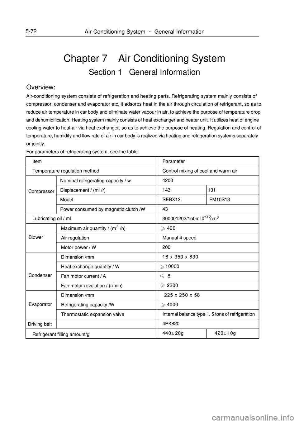
Item
Temperature regulation method
CompressorNominal refrigerating capacity / w
Displacement / (ml /r)
Model
Power consumed by magnetic clutch /W
Lubricating oil / ml
BlowerMaximum air quantity / (m3/h)
Air regulation
Motor power / W
Dimension /mm
Heat exchange quantity / W
Fan motor current / A
Fan motor revolution / (r/min)
Dimension /mm
Refrigerating capacity /W
Thermostatic expansion valve Condenser
Evaporator
Driving belt
Refrigerant filling amount/gChapter 7 Air Conditioning SystemSection 1 General InformationOverview:Air-conditioning system consists of refrigeration and heating parts. Refrigerating system mainly consists of
compressor, condenser and evaporator etc, it adsorbs heat in the air through circulation of refrigerant, so as to
reduce air temperature in car body and eliminate water vapour in air, to achieve the purpose of temperature drop
and dehumidification. Heating system mainly consists of heat exchanger and heater unit. It utilizes heat of engine
cooling water to heat air via heat exchanger, so as to achieve the purpose of heating. Regulation and control of
temperature, humidity and flow rate of air in car body is realized via heating and refrigeration systems separately
or jointly.
For parameters of refrigerating system, see the table:
Parameter
Control mixing of cool and warm air
4200
143 131
SEBX13 FM10S13
43
300001202/150ml cm3 420
Manual 4 speed
200
16 x 350 x 630
10000
8
2200
225 x 250 x 58
4000
Internal balance type 1. 5 tons of refrigeration
4PK820
440±20g 420±10g+20
05-72Air Conditioning System -
General Information
Page 260 of 416

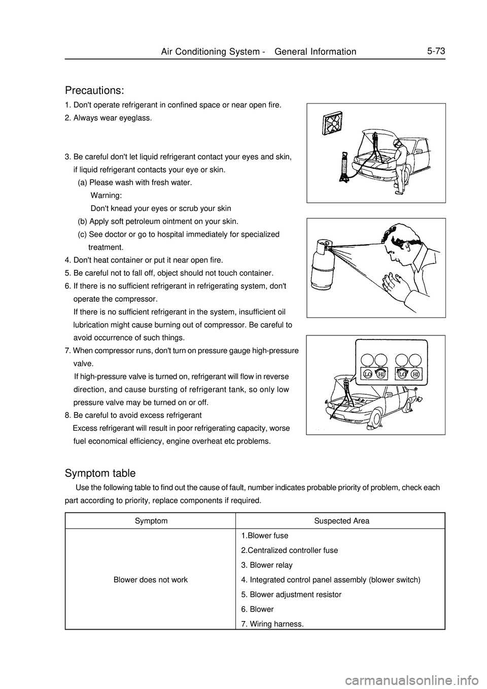
5-73Precautions:1. Don't operate refrigerant in confined space or near open fire.
2. Always wear eyeglass.
3. Be careful don't let liquid refrigerant contact your eyes and skin,
if liquid refrigerant contacts your eye or skin.
(a) Please wash with fresh water.
Warning:
Don't knead your eyes or scrub your skin
(b) Apply soft petroleum ointment on your skin.
(c) See doctor or go to hospital immediately for specialized
treatment.
4. Don't heat container or put it near open fire.
5. Be careful not to fall off, object should not touch container.
6. If there is no sufficient refrigerant in refrigerating system, don't
operate the compressor.
If there is no sufficient refrigerant in the system, insufficient oil
lubrication might cause burning out of compressor. Be careful to
avoid occurrence of such things.
7. When compressor runs, don't turn on pressure gauge high-pressure
valve.
If high-pressure valve is turned on, refrigerant will flow in reverse
direction, and cause bursting of refrigerant tank, so only low
pressure valve may be turned on or off.
8. Be careful to avoid excess refrigerant
Excess refrigerant will result in poor refrigerating capacity, worse
fuel economical efficiency, engine overheat etc problems.Symptom
Blower does not workSymptom table Use the following table to find out the cause of fault, number indicates probable priority of problem, check each
part according to priority, replace components if required.
Suspected Area
1.Blower fuse
2.Centralized controller fuse
3. Blower relay
4. Integrated control panel assembly (blower switch)
5. Blower adjustment resistor
6. Blower
7. Wiring harness.Air Conditioning System -General Information
Page 261 of 416

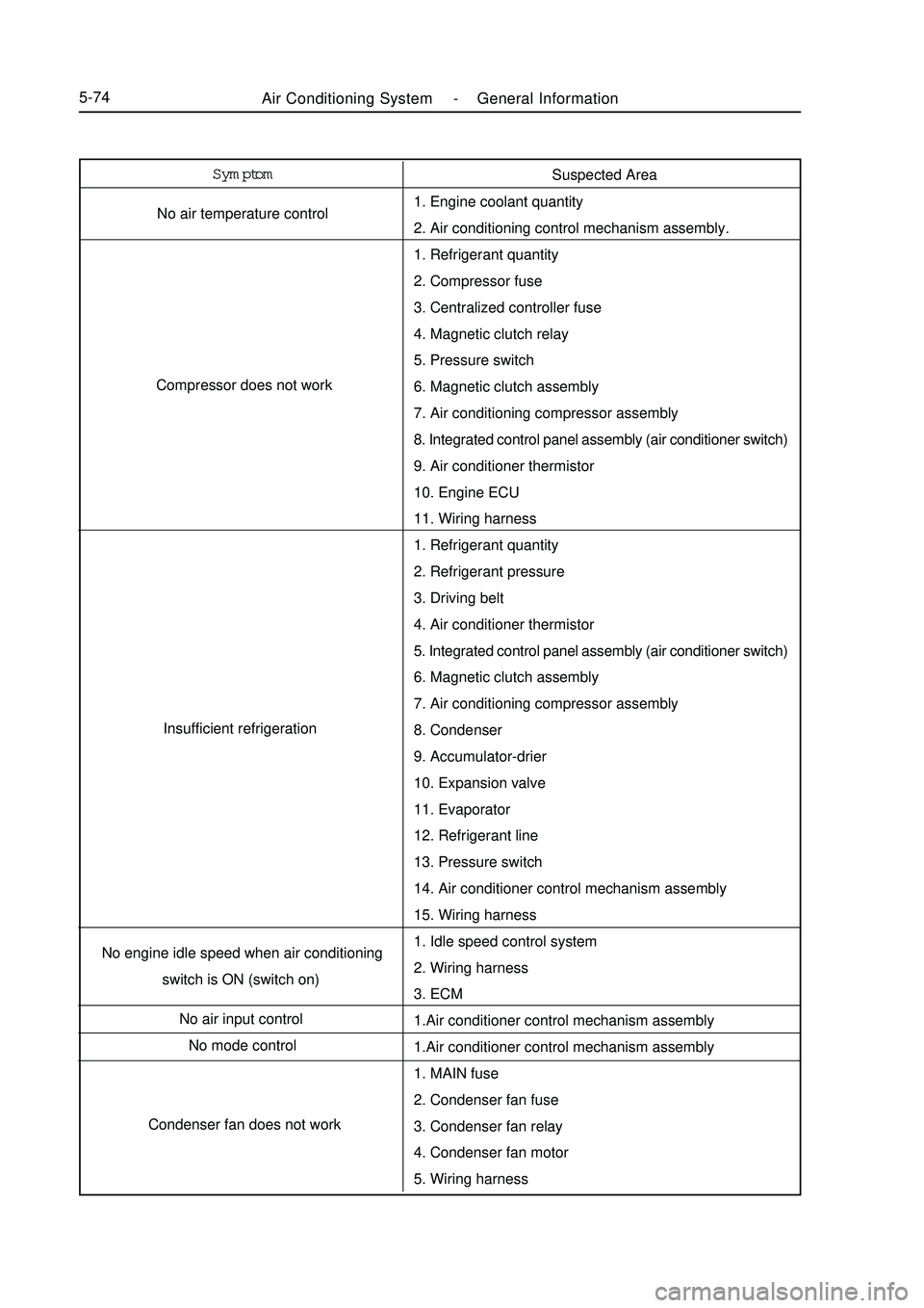
Air Conditioning System -General Information5-74Symptom
No air temperature control
Compressor does not work
Insufficient refrigeration
No engine idle speed when air conditioning
switch is ON (switch on)
No air input control
No mode control
Condenser fan does not workSuspected Area
1. Engine coolant quantity
2. Air conditioning control mechanism assembly.
1. Refrigerant quantity
2. Compressor fuse
3. Centralized controller fuse
4. Magnetic clutch relay
5. Pressure switch
6. Magnetic clutch assembly
7. Air conditioning compressor assembly
8. Integrated control panel assembly (air conditioner switch)
9. Air conditioner thermistor
10. Engine ECU
11. Wiring harness
1. Refrigerant quantity
2. Refrigerant pressure
3. Driving belt
4. Air conditioner thermistor
5. Integrated control panel assembly (air conditioner switch)
6. Magnetic clutch assembly
7. Air conditioning compressor assembly
8. Condenser
9. Accumulator-drier
10. Expansion valve
11. Evaporator
12. Refrigerant line
13. Pressure switch
14. Air conditioner control mechanism assembly
15. Wiring harness
1. Idle speed control system
2. Wiring harness
3. ECM
1.Air conditioner control mechanism assembly
1.Air conditioner control mechanism assembly
1. MAIN fuse
2. Condenser fan fuse
3. Condenser fan relay
4. Condenser fan motor
5. Wiring harness
Page 262 of 416

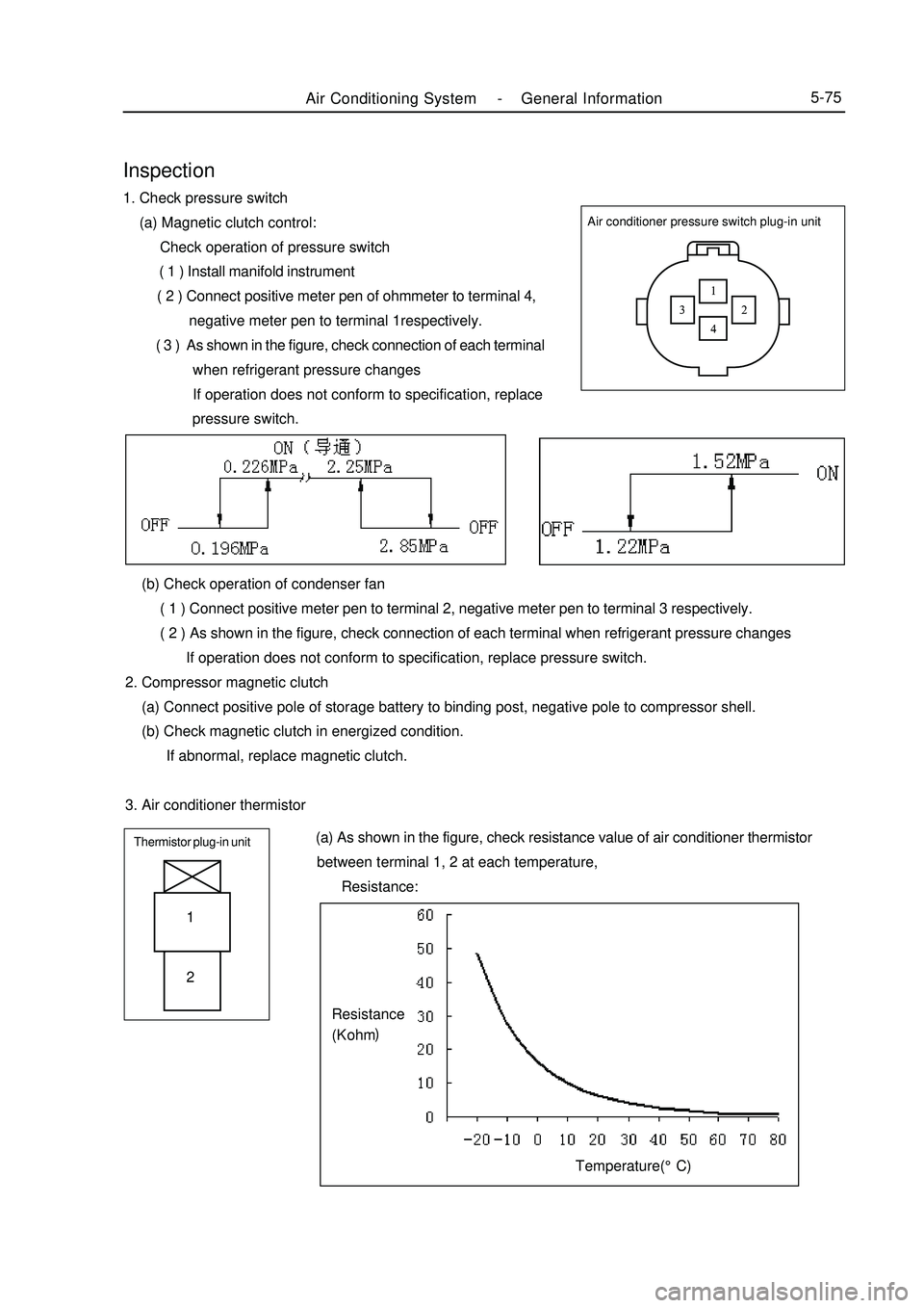
Air Conditioning System -General Information5-75Air conditioner pressure switch plug-in unitInspection1. Check pressure switch
(a) Magnetic clutch control:
Check operation of pressure switch
( 1 ) Install manifold instrument
( 2 ) Connect positive meter pen of ohmmeter to terminal 4,
negative meter pen to terminal 1respectively.
( 3 ) As shown in the figure, check connection of each terminal
when refrigerant pressure changes
If operation does not conform to specification, replace
pressure switch.
(b) Check operation of condenser fan
( 1 ) Connect positive meter pen to terminal 2, negative meter pen to terminal 3 respectively.
( 2 ) As shown in the figure, check connection of each terminal when refrigerant pressure changes
If operation does not conform to specification, replace pressure switch.
2. Compressor magnetic clutch
(a) Connect positive pole of storage battery to binding post, negative pole to compressor shell.
(b) Check magnetic clutch in energized condition.
If abnormal, replace magnetic clutch.
3. Air conditioner thermistorThermistor plug-in unit (a) As shown in the figure, check resistance value of air conditioner thermistor
between terminal 1, 2 at each temperature,
Resistance:1
2Temperature(°C)Resistance
(K ohm)