engine GREAT WALL FLORID 2008 Service Manual
[x] Cancel search | Manufacturer: GREAT WALL, Model Year: 2008, Model line: FLORID, Model: GREAT WALL FLORID 2008Pages: 281, PDF Size: 43.97 MB
Page 271 of 281
Downloaded from www.Manualslib.com manuals search engine GWFLORID Maintenance Manual264
Rear three-point seat belt removal
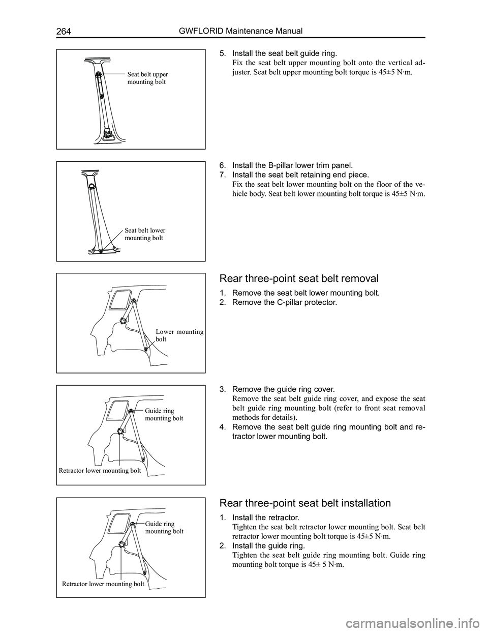
1. Remove the seat belt lower mounting bolt.
2. Remove the C-pillar protector.
3. Remove the guide ring cover.
Remove the seat belt guide ring cover, and expose the seat
belt guide ring mounting bolt (refer to front seat removal
methods for details).
4. Remove the seat belt guide ring mounting bolt and re-
tractor lower mounting bolt.
Rear three-point seat belt installation
1. Install the retractor.
Tighten the seat belt retractor lower mounting bolt. Seat belt
retractor lower mounting bolt torque is 45±5 N·m.
2. Install the guide ring.
Tighten the seat belt guide ring mounting bolt. Guide ring
mounting bolt torque is 45± 5 N·m.
6. Install the B-pillar lower trim panel.
7. Install the seat belt retaining end piece.
Fix the seat belt lower mounting bolt on the floor of the ve-
hicle body. Seat belt lower mounting bolt torque is 45±5 N·m.
5. Install the seat belt guide ring.
Fix the seat belt upper mounting bolt onto the vertical ad-
juster. Seat belt upper mounting bolt torque is 45±5 N·m.Seat belt upper mounting bolt
Seat belt lower mounting bolt
Lower mounting bolt
Guide ring mounting bolt
Retractor lower mounting bolt
Guide ring mounting bolt
Retractor lower mounting bolt
Page 272 of 281
Downloaded from www.Manualslib.com manuals search engine 265Vehicle Body
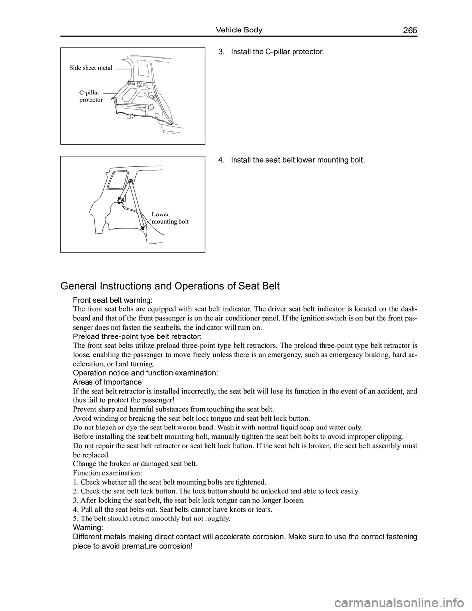
3. Install the C-pillar protector.
General Instructions and Operations of Seat Belt
Front seat belt warning:
The front seat belts are equipped with seat belt indicator. The driver seat belt indicator is located on the dash-
board and that of the front passenger is on the air conditioner panel. If the ignition switch is on but the front pas-
senger does not fasten the seatbelts, the indicator will turn on.
Preload three-point type belt retractor:
The front seat belts utilize preload three-point type belt retractors. The preload three-point type belt retractor is
loose, enabling the passenger to move freely unless there is an emergency, such as emergency braking, hard ac-
celeration, or hard turning.
Operation notice and function examination:
Areas of Importance
If the seat belt retractor is installed incorrectly, the seat belt will lose its function in the event of an accident, and
thus fail to protect the passenger!
Prevent sharp and harmful substances from touching the seat belt.
Avoid winding or breaking the seat belt lock tongue and seat belt lock bu\
tton.
Do not bleach or dye the seat belt woren band. Wash it with neutral liquid soap and water only.
Before installing the seat belt mounting bolt, manually tighten the seat\
belt bolts to avoid improper clipping.
Do not repair the seat belt retractor or seat belt lock button. If the seat belt is broken, the seat belt assembly must
be replaced.
Change the broken or damaged seat belt.
Function examination:
1. Check whether all the seat belt mounting bolts are tightened.
2. Check the seat belt lock button. The lock button should be unlocked and able to lock easily.
3. After locking the seat belt, the seat belt lock tongue can no longer loo\
sen.
4. Pull all the seat belts out. Seat belts cannot have knots or tears.
5. The belt should retract smoothly but not roughly.
Warning:
Different metals making direct contact will accelerate corrosion. Make sure to use the correct fastening
piece to avoid premature corrosion!
4. Install the seat belt lower mounting bolt.
Lower mounting bolt
Side sheet metal
C-pillar protector
Page 273 of 281
Downloaded from www.Manualslib.com manuals search engine GWFLORID Maintenance Manual266
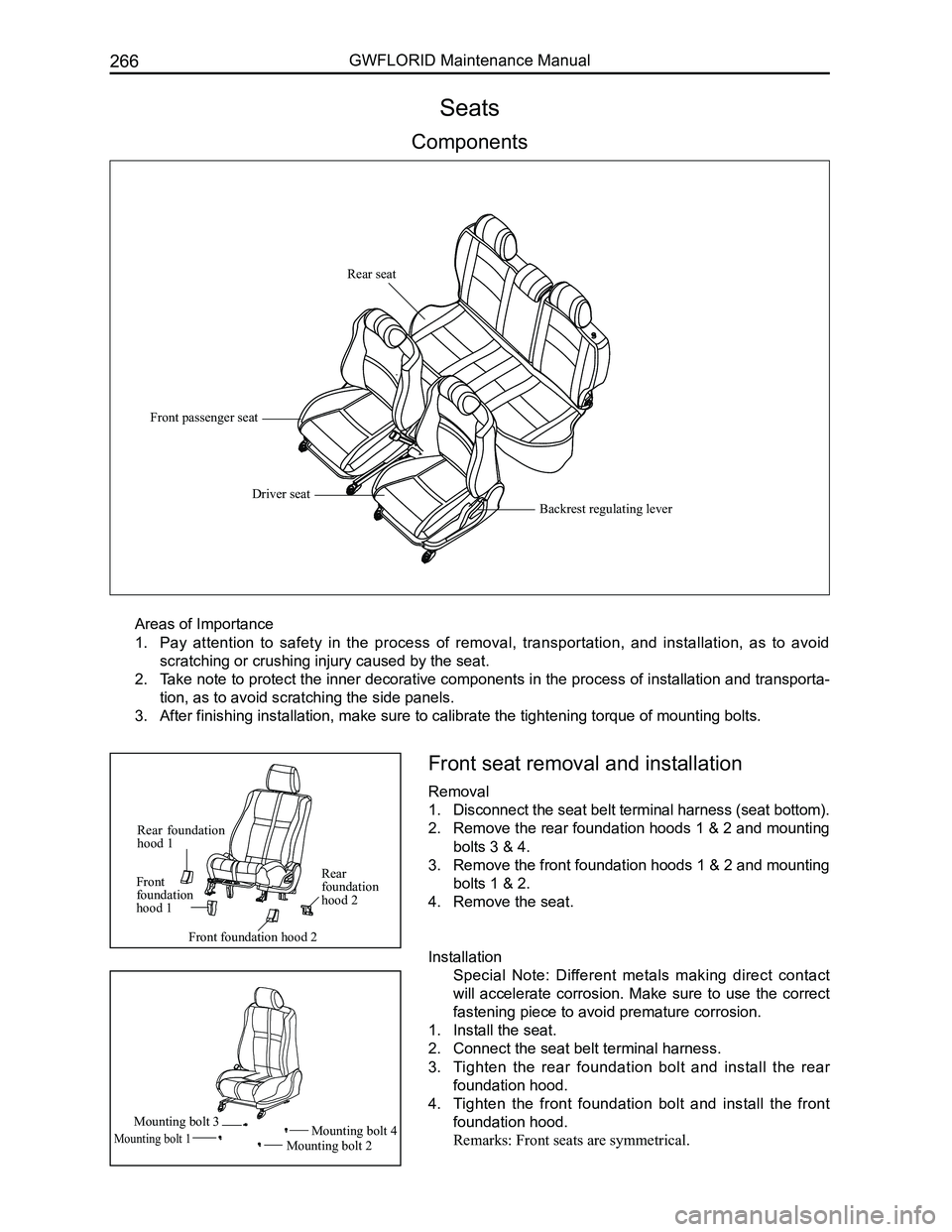
Front seat removal and installation
Removal
1. Disconnect the seat belt terminal harness (seat bottom).
2. Remove the rear foundation hoods 1 & 2 and mounting
bolts 3 & 4.
3. Remove the front foundation hoods 1 & 2 and mounting
bolts 1 & 2.
4. Remove the seat.
Installation
Special Note: Different metals making direct contact
will accelerate corrosion. Make sure to use the correct
fastening piece to avoid premature corrosion.
1. Install the seat.
2. Connect the seat belt terminal harness.
3. Tighten the rear foundation bolt and install the rear
foundation hood.
4. Tighten the front foundation bolt and install the front
foundation hood.
Remarks: Front seats are symmetrical.
Seats
Components
Areas of Importance
1. Pay attention to safety in the process of removal, transportation, and installation, as to avoid
scratching or crushing injury caused by the seat.
2. Take note to protect the inner decorative components in the process of installation and transporta-
tion, as to avoid scratching the side panels.
3. After finishing installation, make sure to calibrate the tightening torq\
ue of mounting bolts.
Rear seat
Front passenger seat
Driver seat
Backrest regulating lever
Rear foundation hood 1
Rear foundation hood 2
Front foundation hood 1
Front foundation hood 2
Mounting bolt 1Mounting bolt 2
Mounting bolt 4Mounting bolt 3
Page 274 of 281
Downloaded from www.Manualslib.com manuals search engine 267Vehicle Body
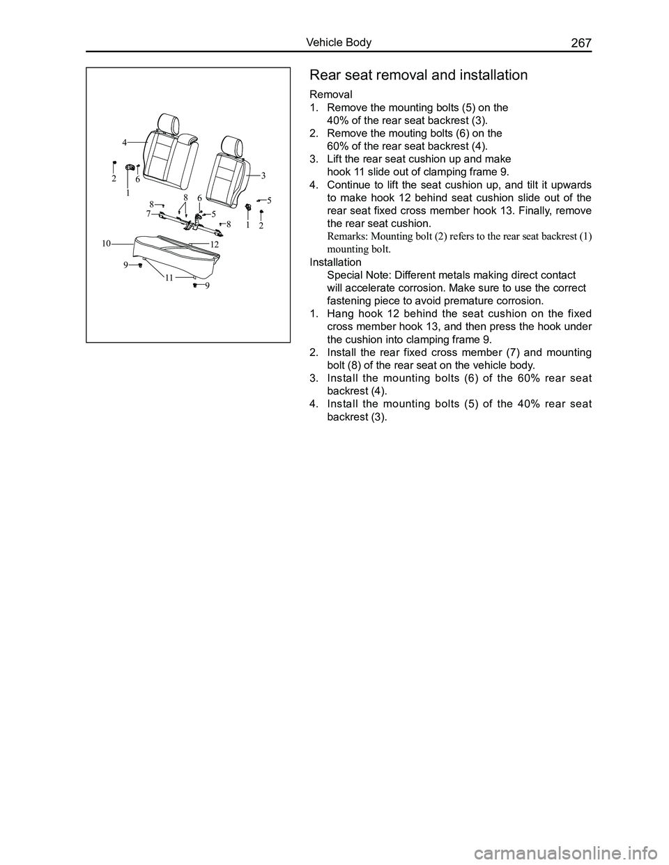
Rear seat removal and installation
Removal
1. Remove the mounting bolts (5) on the
40% of the rear seat backrest (3).
2. Remove the mouting bolts (6) on the
60% of the rear seat backrest (4).
3. Lift the rear seat cushion up and make
hook 11 slide out of clamping frame 9.
4. Continue to lift the seat cushion up, and tilt it upwards
to make hook 12 behind seat cushion slide out of the
rear seat fixed cross member hook 13. Finally, remove
the rear seat cushion.
Remarks: Mounting bolt (2) refers to the rear seat backrest (1)
mounting bolt.
Installation
Special Note: Different metals making direct contact
will accelerate corrosion. Make sure to use the correct
fastening piece to avoid premature corrosion.
1. Hang hook 12 behind the seat cushion on the fixed
cross member hook 13, and then press the hook under
the cushion into clamping frame 9.
2. Install the rear fixed cross member (7) and mounting
bolt (8) of the rear seat on the vehicle body.
3. Install the mounting bolts (6) of the 60% rear seat
backrest (4).
4. Install the mounting bolts (5) of the 40% rear seat
backrest (3).
1
23
4
5
6
7
8
9
10
9
21
5
68
8
11
12
Page 275 of 281
Downloaded from www.Manualslib.com manuals search engine GWFLORID Maintenance Manual268
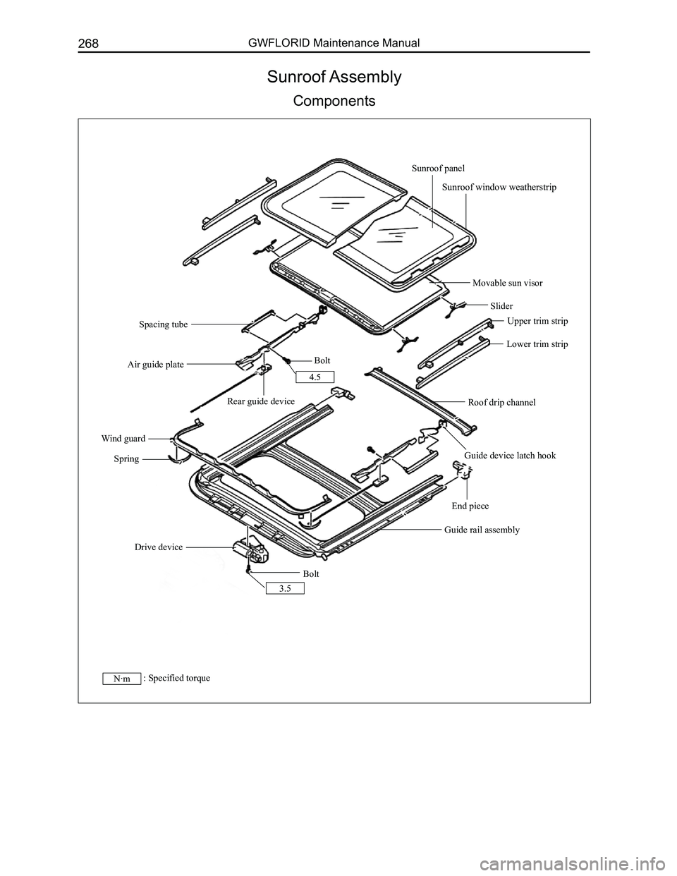
Sunroof Assembly
Components
N·m: Specified torque
Sunroof panel
Sunroof window weatherstrip
Movable sun visor
Slider
Upper trim strip
Lower trim strip
Roof drip channel
Guide device latch hook
End piece
Guide rail assembly
Bolt
Spring
Wind guard
Bolt
Rear guide device
Air guide plate
Spacing tube
Drive device
4.5
3.5
Page 276 of 281
Downloaded from www.Manualslib.com manuals search engine 269Vehicle Body
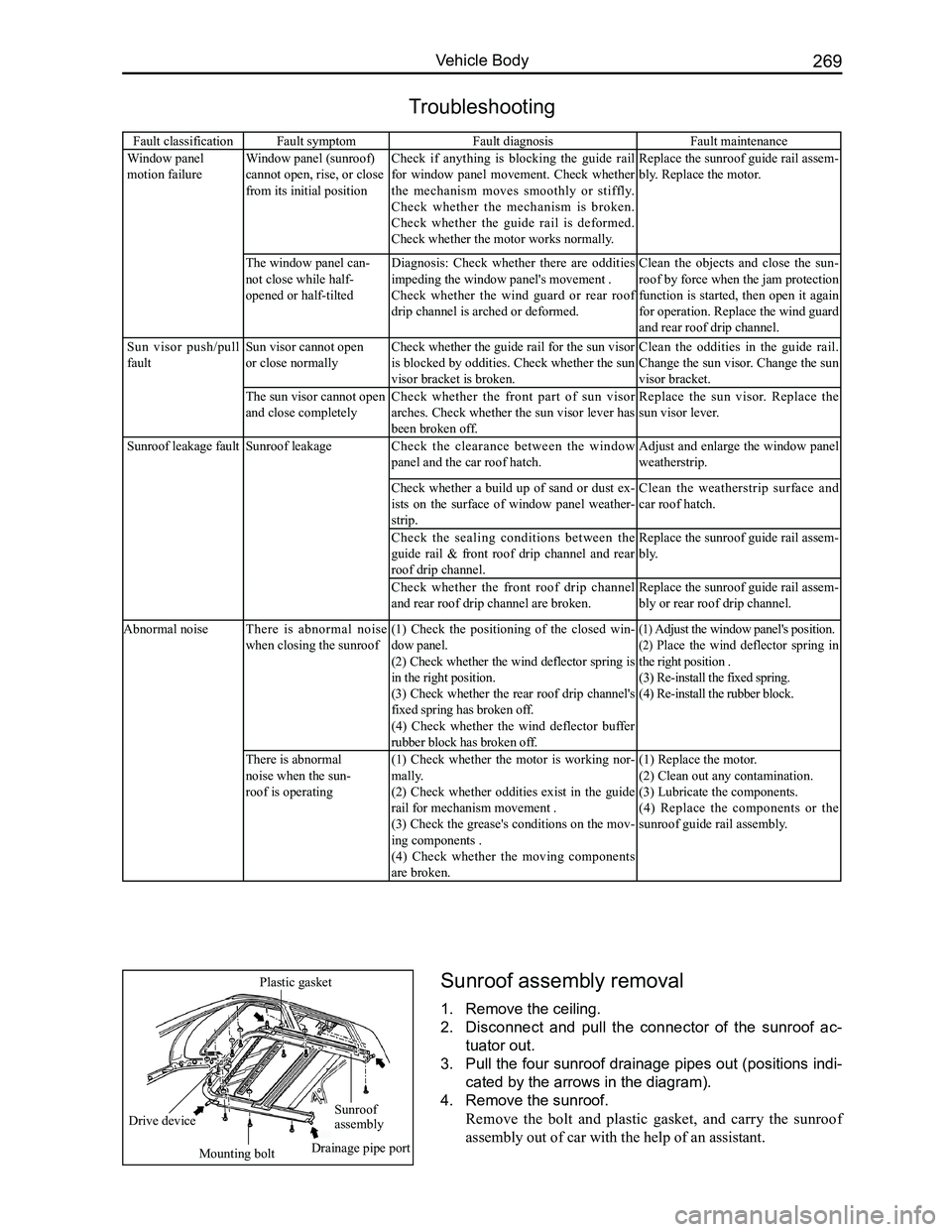
Fault classificationFault symptomFault diagnosisFault maintenance
Window panel
motion failure
Window panel (sunroof)
cannot open, rise, or close
from its initial position
Check if anything is blocking the guide rail
for window panel movement. Check whether
the mechanism moves smoothly or stiffly.
Check whether the mechanism is broken.
Check whether the guide rail is deformed.
Check whether the motor works normally.
Replace the sunroof guide rail assem-
bly. Replace the motor.
The window panel can-
not close while half-
opened or half-tilted
Diagnosis: Check whether there are oddities
impeding the window panel's movement .
Check whether the wind guard or rear roof
drip channel is arched or deformed.
Clean the objects and close the sun-
roof by force when the jam protection
function is started, then open it again
for operation. Replace the wind guard
and rear roof drip channel.
Sun visor push/pull
fault
Sun visor cannot open
or close normally
Check whether the guide rail for the sun visor
is blocked by oddities. Check whether the sun
visor bracket is broken.
Clean the oddities in the guide rail.
Change the sun visor. Change the sun
visor bracket.
The sun visor cannot open
and close completely
Check whether the front part of sun visor
arches. Check whether the sun visor lever has
been broken off.
Replace the sun visor. Replace the
sun visor lever.
Sunroof leakage fault Sunroof leakageCheck the clearance between the window
panel and the car roof hatch.
Adjust and enlarge the window panel
weatherstrip.
Check whether a build up of sand or dust ex-
ists on the surface of window panel weather-
strip.
Clean the weatherstrip surface and
car roof hatch.
Check the sealing conditions between the
guide rail & front roof drip channel and rear
roof drip channel.
Replace the sunroof guide rail assem-
bly.
Check whether the front roof drip channel
and rear roof drip channel are broken.
Replace the sunroof guide rail assem-
bly or rear roof drip channel.
Abnormal noiseThere is abnormal noise
when closing the sunroof
(1) Check the positioning of the closed win-
dow panel.
(2) Check whether the wind deflector spring is
in the right position.
(3) Check whether the rear roof drip channel's
fixed spring has broken off.
(4) Check whether the wind deflector buffer
rubber block has broken off.
(1) Adjust the window panel's position.
(2) Place the wind deflector spring in
the right position .
(3) Re-install the fixed spring.
(4) Re-install the rubber block.
There is abnormal
noise when the sun-
roof is operating
(1) Check whether the motor is working nor-
mally.
(2) Check whether oddities exist in the guide
rail for mechanism movement .
(3) Check the grease's conditions on the mov-
ing components .
(4) Check whether the moving components
are broken.
(1) Replace the motor.
(2) Clean out any contamination.
(3) Lubricate the components.
(4) Replace the components or the
sunroof guide rail assembly.
Troubleshooting
Sunroof assembly removal
1. Remove the ceiling.
2. Disconnect and pull the connector of the sunroof ac-
tuator out.
3. Pull the four sunroof drainage pipes out (positions indi-
cated by the arrows in the diagram).
4. Remove the sunroof.
Remove the bolt and plastic gasket, and carry the sunroof
assembly out of car with the help of an assistant.
Sunroof assembly
Mounting bolt
Drive device
Plastic gasket
Drainage pipe port
Page 277 of 281
Downloaded from www.Manualslib.com manuals search engine GWFLORID Maintenance Manual270
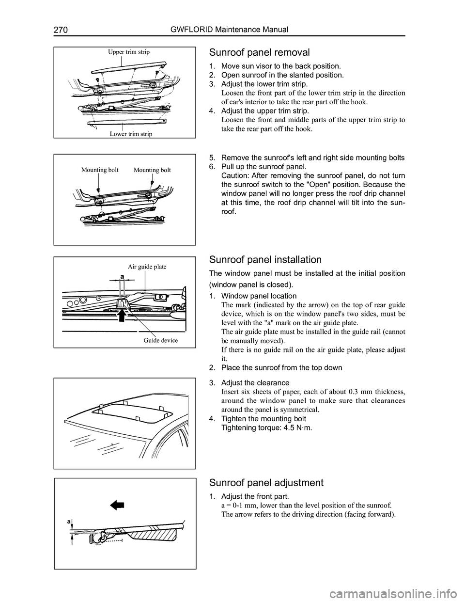
Sunroof panel removal
1. Move sun visor to the back position.
2. Open sunroof in the slanted position.
3. Adjust the lower trim strip.
Loosen the front part of the lower trim strip in the direction
of car's interior to take the rear part off the hook.
4. Adjust the upper trim strip.
Loosen the front and middle parts of the upper trim strip to
take the rear part off the hook.
5. Remove the sunroof's left and right side mounting bolts
6. Pull up the sunroof panel.
Caution: After removing the sunroof panel, do not turn
the sunroof switch to the "Open" position. Because the
window panel will no longer press the roof drip channel
at this time, the roof drip channel will tilt into the sun-
roof.
Sunroof panel installation
The window panel must be installed at the initial position
(window panel is closed).
1. Window panel location
The mark (indicated by the arrow) on the top of rear guide
device, which is on the window panel's two sides, must be
level with the "a" mark on the air guide plate.
The air guide plate must be installed in the guide rail (cannot
be manually moved).
If there is no guide rail on the air guide plate, please adjust
it.
2. Place the sunroof from the top down
3. Adjust the clearance
Insert six sheets of paper, each of about 0.3 mm thickness,
around the window panel to make sure that clearances
around the panel is symmetrical.
4. Tighten the mounting bolt
Tightening torque: 4.5 N·m.
Sunroof panel adjustment
1. Adjust the front part.
a = 0-1 mm, lower than the level position of the sunroof.
The arrow refers to the driving direction (facing forward).
Lower trim strip
Upper trim strip
Mounting boltMounting bolt
Guide device
Air guide plate
Page 278 of 281
Downloaded from www.Manualslib.com manuals search engine 271Vehicle Body
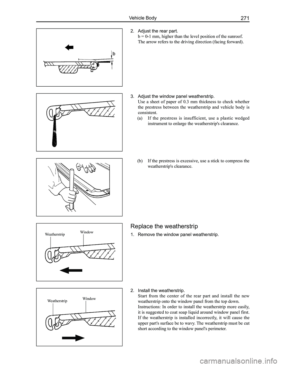
2. Adjust the rear part.
b = 0-1 mm, higher than the level position of the sunroof.
The arrow refers to the driving direction (facing forward).
3. Adjust the window panel weatherstrip.
Use a sheet of paper of 0.3 mm thickness to check whether
the prestress between the weatherstrip and vehicle body is
consistent.
(a) If the prestress is insufficient, use a plastic wedged
instrument to enlarge the weatherstrip's clearance.
(b) If the prestress is excessive, use a stick to compress the
weatherstrip's clearance.
Replace the weatherstrip
1. Remove the window panel weatherstrip.
2. Install the weatherstrip.
Start from the center of the rear part and install the new
weatherstrip onto the window panel from the top down.
Instructions: In order to install the weatherstrip more easily,
it is suggested to coat soap liquid around window panel first.
If the weatherstrip is installed incorrectly, it will cause the
upper part's surface be to wavy. The weatherstrip must be cut
short according to the window panel's perimeter.
WeatherstripWindow
WeatherstripWindow
Page 279 of 281
Downloaded from www.Manualslib.com manuals search engine GWFLORID Maintenance Manual272
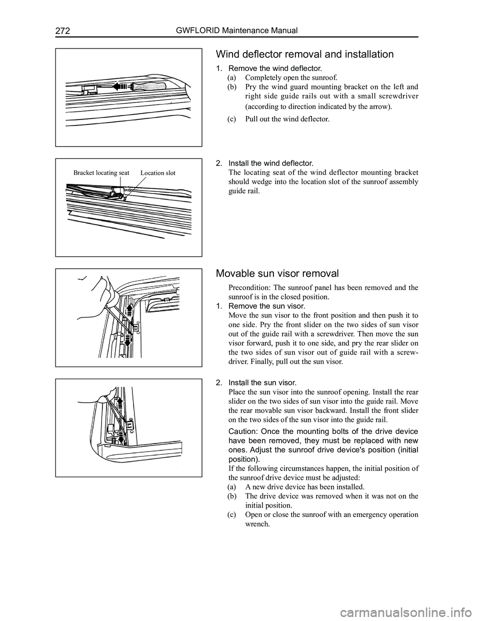
Wind deflector removal and installation
1. Remove the wind deflector.
(a) Completely open the sunroof.
(b) Pry the wind guard mounting bracket on the left and
right side guide rails out with a small screwdriver
(according to direction indicated by the arrow).
(c) Pull out the wind deflector.
2. Install the wind deflector.
The locating seat of the wind deflector mounting bracket
should wedge into the location slot of the sunroof assembly
guide rail.
Movable sun visor removal
Precondition: The sunroof panel has been removed and the
sunroof is in the closed position.
1. Remove the sun visor.
Move the sun visor to the front position and then push it to
one side. Pry the front slider on the two sides of sun visor
out of the guide rail with a screwdriver. Then move the sun
visor forward, push it to one side, and pry the rear slider on
the two sides of sun visor out of guide rail with a screw-
driver. Finally, pull out the sun visor.
2. Install the sun visor.
Place the sun visor into the sunroof opening. Install the rear
slider on the two sides of sun visor into the guide rail. Move
the rear movable sun visor backward. Install the front slider
on the two sides of the sun visor into the guide rail.
Caution: Once the mounting bolts of the drive device
have been removed, they must be replaced with new
ones. Adjust the sunroof drive device's position (initial
position).
If the following circumstances happen, the initial position of
the sunroof drive device must be adjusted:
(a) A new drive device has been installed.
(b) The drive device was removed when it was not on the
initial position.
(c) Open or close the sunroof with an emergency operation
wrench.
Location slotBracket locating seat
Page 280 of 281
Downloaded from www.Manualslib.com manuals search engine 273Vehicle Body
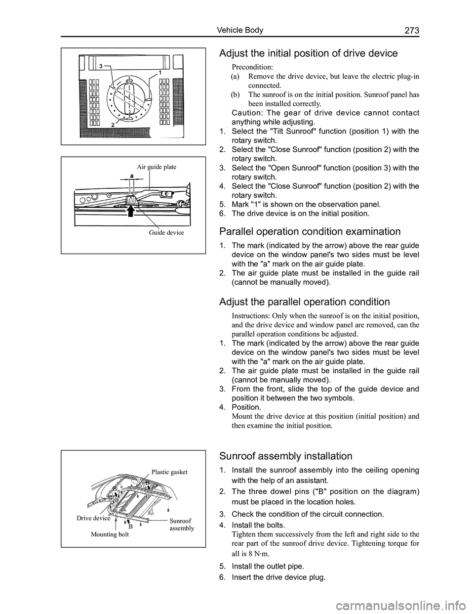
Adjust the initial position of drive device
Precondition:
(a) Remove the drive device, but leave the electric plug-in
connected.
(b) The sunroof is on the initial position. Sunroof panel has
been installed correctly.
Caution: The gear of drive device cannot contact
anything while adjusting.
1. Select the "Tilt Sunroof" function (position 1) with the
rotary switch.
2. Select the "Close Sunroof" function (position 2) with the
rotary switch.
3. Select the "Open Sunroof" function (position 3) with the
rotary switch.
4. Select the "Close Sunroof" function (position 2) with the
rotary switch.
5. Mark "1" is shown on the observation panel.
6. The drive device is on the initial position.
Parallel operation condition examination
1. The mark (indicated by the arrow) above the rear guide
device on the window panel's two sides must be level
with the "a" mark on the air guide plate.
2. The air guide plate must be installed in the guide rail
(cannot be manually moved).
Adjust the parallel operation condition
Instructions: Only when the sunroof is on the initial position,
and the drive device and window panel are removed, can the
parallel operation conditions be adjusted.
1. The mark (indicated by the arrow) above the rear guide
device on the window panel's two sides must be level
with the "a" mark on the air guide plate.
2. The air guide plate must be installed in the guide rail
(cannot be manually moved).
3. From the front, slide the top of the guide device and
position it between the two symbols.
4. Position.
Mount the drive device at this position (initial position) and
then examine the initial position.
Sunroof assembly installation
1. Install the sunroof assembly into the ceiling opening
with the help of an assistant.
2. The three dowel pins ("B" position on the diagram)
must be placed in the location holes.
3. Check the condition of the circuit connection.
4. Install the bolts.
Tighten them successively from the left and right side to the
rear part of the sunroof drive device. Tightening torque for
all is 8 N·m.
5. Install the outlet pipe.
6. Insert the drive device plug.
Air guide plate
Guide device
Sunroof assembly
Plastic gasket
Mounting bolt
Drive device
B
BB