door lock GREAT WALL FLORID 2008 Service Manual
[x] Cancel search | Manufacturer: GREAT WALL, Model Year: 2008, Model line: FLORID, Model: GREAT WALL FLORID 2008Pages: 281, PDF Size: 43.97 MB
Page 6 of 281
Downloaded from www.Manualslib.com manuals search engine Technical Requirements ..................................................................................\
........141
Chapter Nine: Vehicle Body Electrical System ........................................................................\
.142
Basic Information on the Electrical System .............................................................143
Fuse Box ...................................................................................\
...............................144
Overall Vehicle’s Grounding Point Schematics ........................................................150
Key Electrical Component’s Module Schematics for the Overall Vehicle ................151
Wire Harness Distribution Chart for the Overall Vehicle ..........................................152
Wire Harness Relationship and Plug-in Connections Numbered Diagram ..............155
Wire Harness Plug-in Connectors and Pin Function Diagram .................................156
Electrical Wiring Diagram for the Overall Vehicle ....................................................167
Chapter Ten: Electrical Accessories ........................................................................\
.................177
Reverse Sensor ..................................................................................\
.....................178
Combination Meter ..................................................................................\
................180
Central Door Lock ...................................................................................\
.................181
Power Windows ..................................................................................\
.....................184
Immobilizer System ..................................................................................\
...............186
CD Player ..................................................................................\
..............................193
DVD Player ..................................................................................\
............................195
Chapter Eleven: Air Conditioning System........................................................................\
........202
Areas of Importance ..................................................................................\
..............203
Technical Parameters ..................................................................................\
............203
Troubleshooting ..................................................................................\
.....................204
Air Conditioning System’s Structure Diagram and Fundamentals ...........................207
Air Conditioning System Overview ..........................................................................207
Air Conditioning System Terminal Definition ............................................................208
Compressor ..................................................................................\
...........................208
Electromagnetic Clutch ...................................................................................\
.........210
Vacuuming and Charging Refrigerant ......................................................................211
Filling Quantity and Method for Refrigerant Oil ........................................................212
Daily Maintenance of the Air Conditioning System .................................................212
Chapter Twelve: Airbags ........................................................................\
...................................213
Airbag Electronic Control Unit ..................................................................................214
Diagnostic Scanner ...................................................................................\
...............215
Troubleshooting ..................................................................................\
.....................216
Vehicle Collision Diagnostics ..................................................................................\
.226
Removal Method for Individual Components ...........................................................227
Driver Side Airbag Module (DAB), Front Passenger Side
Airbag Module (PAB), Clock Spring, and Steering Wheel .......................................228
Airbag Module Disposal ...................................................................................\
........230
Page 7 of 281
Downloaded from www.Manualslib.com manuals search engine Airbag’s Diagnostic Methods Without a Diagnostic Scanner ...................................232
Chapter Thirteen: Vehicle Body ........................................................................\
........................233
Front Door Lock Assembly ...................................................................................\
....234
Rear Door Lock Assembly ..................................................................................\
.....237
Trunk Door Lock Assembly ...................................................................................\
...239
Wiper Arm and Vent Panel Assembly ......................................................................240
Front & Rear Window Glasses ................................................................................241
Dashboard ..................................................................................\
.............................242
Cooling Unit ..................................................................................\
...........................246
Front Door Assembly ..................................................................................\
.............248
Rear Door Assembly ...................................................................................\
.............251
Trunk Door Assembly ...................................................................................\
............254
Front Bumper ...................................................................................\
........................256
Rear Bumper ..................................................................................\
.........................259
Seat Belt ..................................................................................\
................................262
Seats ...................................................................................\
.....................................266
Sunroof Assembly ...................................................................................\
.................268
Page 24 of 281
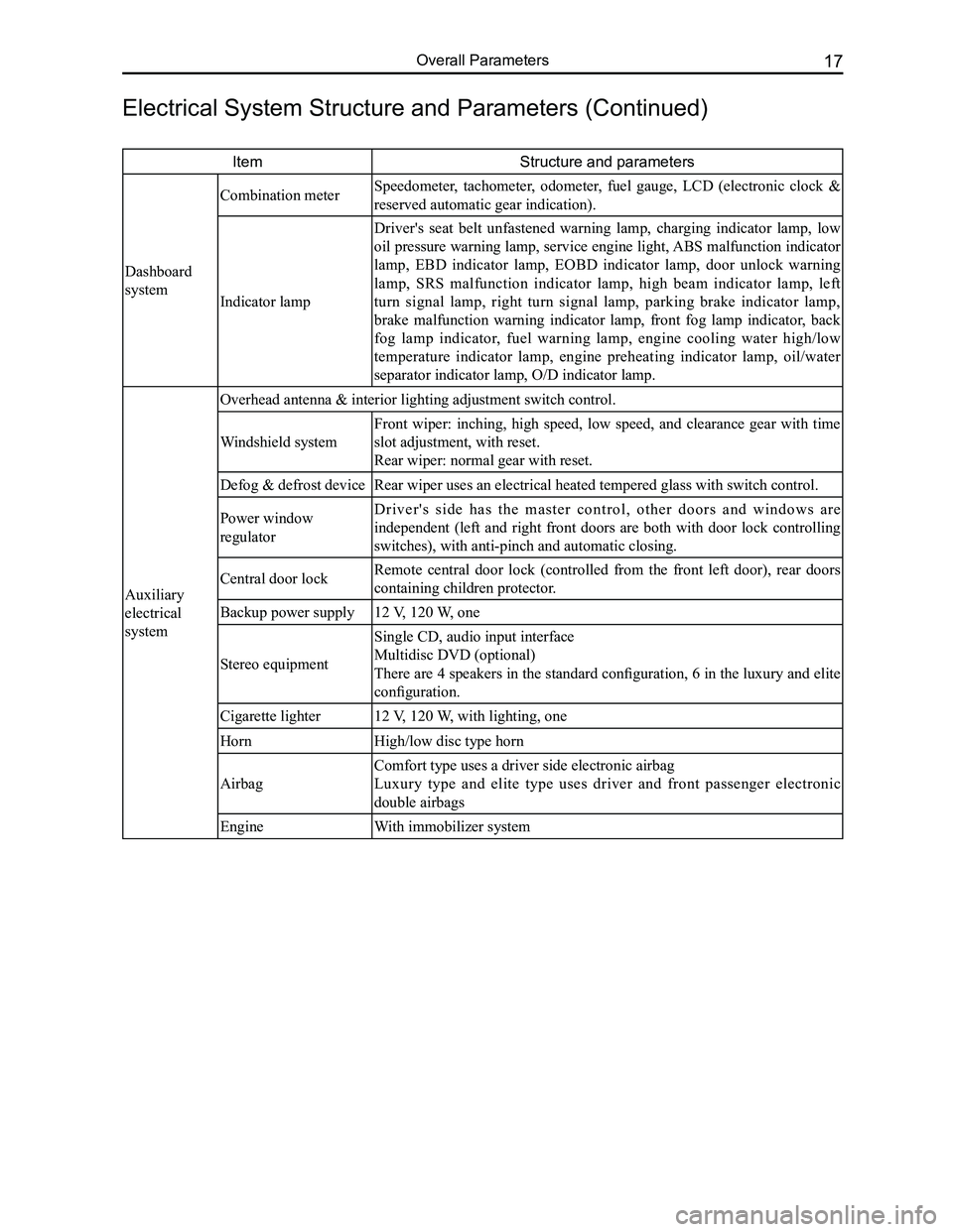
Downloaded from www.Manualslib.com manuals search engine 17Overall Parameters
ItemStructure and parameters
Dashboard
system
Combination meter Speedometer, tachometer, odometer, fuel gauge, LCD (electronic clock &
reserved automatic gear indication).
Indicator lamp
Driver's seat belt unfastened warning lamp, charging indicator lamp, low
oil pressure warning lamp, service engine light, ABS malfunction indicator
lamp, EBD indicator lamp, EOBD indicator lamp, door unlock warning
lamp, SRS malfunction indicator lamp, high beam indicator lamp, left
turn signal lamp, right turn signal lamp, parking brake indicator lamp,
brake malfunction warning indicator lamp, front fog lamp indicator, back
fog lamp indicator, fuel warning lamp, engine cooling water high/low
temperature indicator lamp, engine preheating indicator lamp, oil/water
separator indicator lamp, O/D indicator lamp.
Auxiliary
electrical
system
Overhead antenna & interior lighting adjustment switch control.
Windshield system
Front wiper: inching, high speed, low speed, and clearance gear with time
slot adjustment, with reset.
Rear wiper: normal gear with reset.
Defog & defrost deviceRear wiper uses an electrical heated tempered glass with switch control.\
Power window
regulator
D r i v e r ' s s i d e h a s t h e m a s t e r c o n t r o l , o t h e r d o o r s a n d w i n d o w s a r e
independent (left and right front doors are both with door lock controlling
switches), with anti-pinch and automatic closing.
Central door lockRemote central door lock (controlled from the front left door), rear doors
containing children protector.
Backup power supply12 V, 120 W, one
Stereo equipment
Single CD, audio input interface
Multidisc DVD (optional)
There are 4 speakers in the standard configuration, 6 in the luxury and elite
configuration.
Cigarette lighter12 V, 120 W, with lighting, one
HornHigh/low disc type horn
Airbag
Comfort type uses a driver side electronic airbag
Luxury type and elite type uses driver and front passenger electronic
double airbags
EngineWith immobilizer system
Electrical System Structure and Parameters (Continued)
Page 151 of 281
Downloaded from www.Manualslib.com manuals search engine GWFLORID Maintenance Manual144
Double-colored wire: Primary color is Red, secondary color is Blue, mark\
ed as RBl.
0.5BrGr means Brown wire with a Gray fine wire, and sectional area is 0.\
5 mm2.
Areas of importance in circuit maintenance
1. Before operating any electronic devices, and when tools or maintenance devices may easily make
contact with an uncovered electronic terminal, please make sure to turn the ignition switch to the LOCK
position, and then disconnect the battery's negative cable to avoid injury or vehicle damage. When the
ignition switch is on the ON position, please do not disconnect the battery's connecting wire or take out
the power's fuse, regardless if the engine is running or not.Otherwise it would seriously damage the
ECU and related microelectronic devices such as sensors.
2. When changing the fuse, please make sure that the new fuse possesses the proper current rating,
and is not above or below this rating.
3. When repairing the wire harnesses of the airbag and pretensioner, only specified contact points,
plugs, and wires are allowed to be used.
4. Before repairing the wire harness, make sure to eliminate any factor that might cause damage,
for example, the edge of a vehicle body part is too sharp, or the used electronics are damaged or
corroded.
5. Shielded wire should not be repaired, it must be replaced entirely once it is damaged.
6. Unless it is specified during the test, please do not use an analog multimeter to test the ECU and
sensor, instead use a high-impedance digital multimeter (internal resistance should be ≥10 kΩ) or a
vehicle multimeter for inspection.
7. When inspecting the connector with a digital multimeter, take the waterproof rubber cover off the
connector, and tightly insert the test pen along the connecting terminal. Don't use too much force, as
to avoid cracking the connector.
Circuit inspection steps
The principle of troubleshooting is to confirm the "possible cause". Once the possible cause is confirmed, the
components that need to be inspected are limited to the components that are related to the possible cause. The
confirmed possible cause should be based on theory and be supported by facts, but not just by intuition. If
one tries to solve the problem but does not adopt the proper troubleshooting steps, it may make the problem
worse. Then the possible cause not only can't be confirmed, but also maintenance can't be performed properly.
Troubleshooting should adhere to the four steps below:
1. Observe the symptoms carefully, inspect if there is anything else abnormal, and record it.
2. While confirming the possible causes, study the circuit diagram carefully, and regard it as a whole
system in order to understand the circuit. Thorough knowledge of switches, relays, and other
electronic components is obligatory for proper analysis.
3. Inspect and eliminate the problems one by one until the cause is found.
4. After the malfunction is fixed, make sure to check if the inspected system is working properly, and also
check if the maintenance may have caused any new problems.
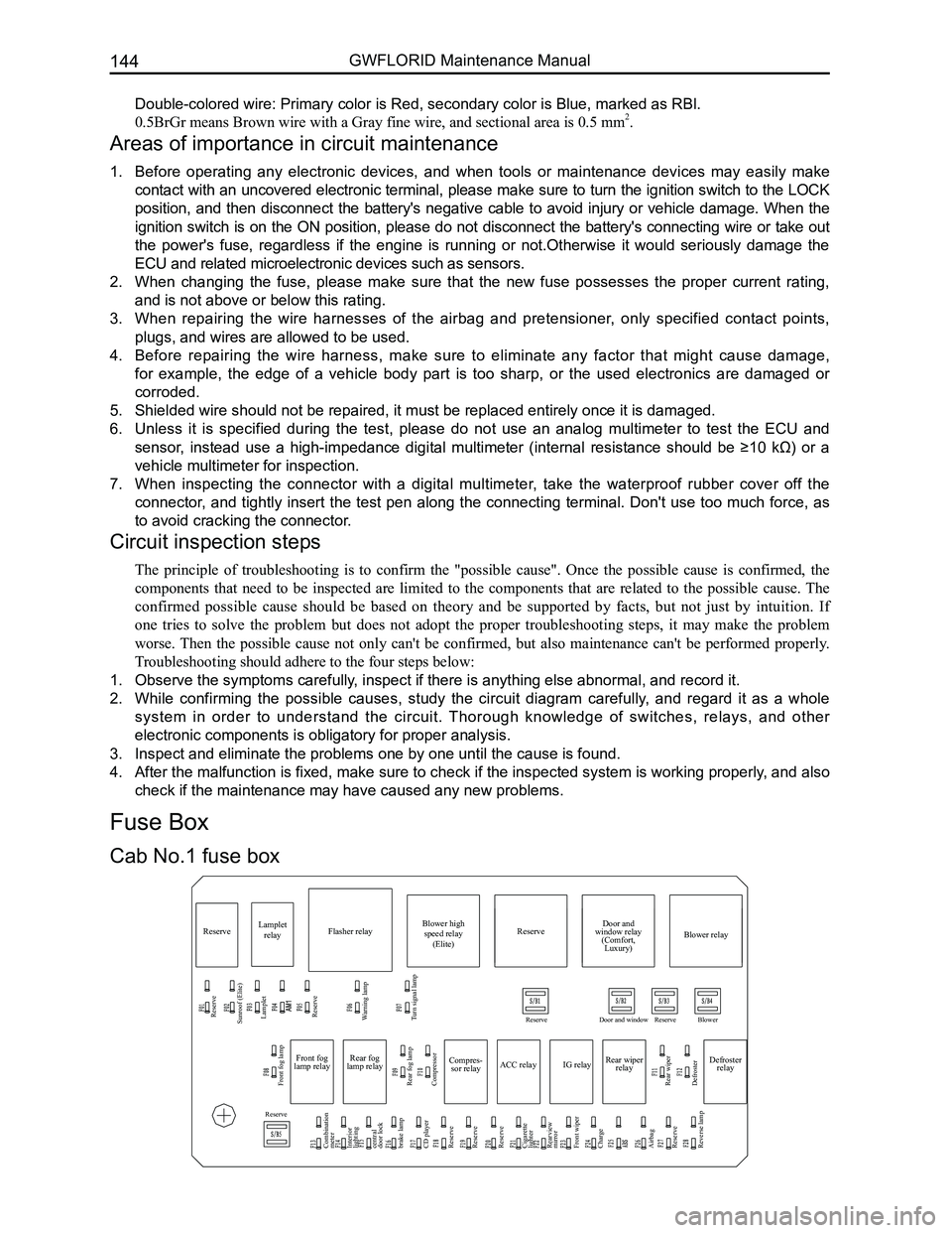
Compres-
sor relay
Reserve
Sunroof (Elite) Lamplet
Reserve
Reserve
Reserve
Reserve Door and window Reserve Blower
Lamplet
relay Flasher relay Blower high
speed relay (Elite) Door and
window relay (Comfort, Luxury) Blower relay
Reserve
Front fog lamp
Combination
meter
Interior
lighting
central
door lock
brake lamp
CD player
Reserve
Reserve
Reserve
Cigarette
lighter
Rearview
mirror
Front wiper
Charge
Airbag
Reserve
Reverse lamp Rear fog lamp
Rear wiper
Defroster Compressor
ACC relay
IG relayRear wiper
relay Defroster
relay
Front fog
lamp relay Rear fog
lamp relay
Warning lamp
Turn signal lamp
Cab No.1 fuse box
Fuse Box
Page 152 of 281
Downloaded from www.Manualslib.com manuals search engine 145Vehicle Body Electronic System
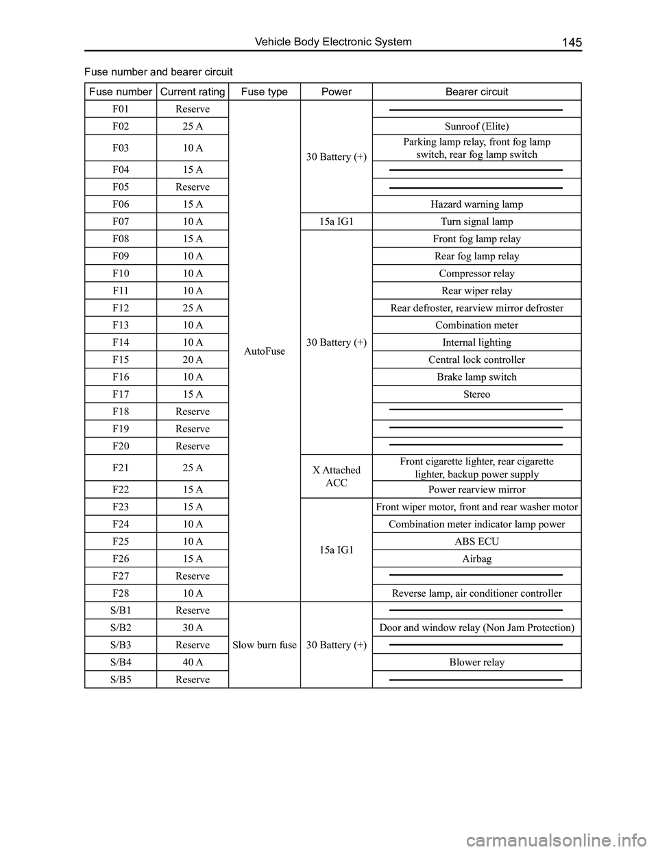
Fuse numberCurrent ratingFuse typePowerBearer circuit
F01Reserve
AutoFuse
30 Battery (+)
F0225 ASunroof (Elite)
F0310 AParking lamp relay, front fog lamp
switch, rear fog lamp switch
F0415 A
F05Reserve
F0615 AHazard warning lamp
F0710 A15a IG1 Turn signal lamp
F0815 A
30 Battery (+)
Front fog lamp relay
F0910 ARear fog lamp relay
F1010 ACompressor relay
F1110 ARear wiper relay
F1225 ARear defroster, rearview mirror defroster
F1310 ACombination meter
F1410 AInternal lighting
F1520 ACentral lock controller
F1610 ABrake lamp switch
F1715 AStereo
F18Reserve
F19Reserve
F20Reserve
F2125 AX Attached
ACC
Front cigarette lighter, rear cigarette
lighter, backup power supply
F2215 APower rearview mirror
F2315 A
15a IG1
Front wiper motor, front and rear washer motor
F2410 ACombination meter indicator lamp power
F2510 AABS ECU
F2615 AAirbag
F27Reserve
F2810 AReverse lamp, air conditioner controller
S/B1Reserve
Slow burn fuse 30 Battery (+)
S/B230 ADoor and window relay (Non Jam Protection)
S/B3Reserve
S/B440 ABlower relay
S/B5Reserve
Fuse number and bearer circuit
Page 158 of 281
Downloaded from www.Manualslib.com manuals search engine 151Vehicle Body Electronic System
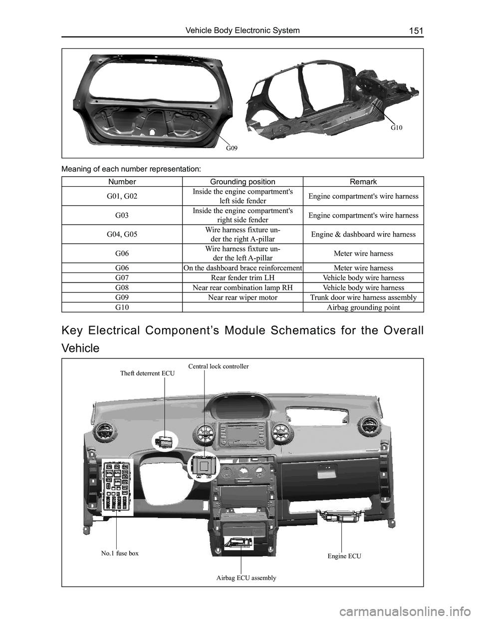
G09
NumberGrounding positionRemark
G01, G02Inside the engine compartment's
left side fenderEngine compartment's wire harness
G03Inside the engine compartment's
right side fenderEngine compartment's wire harness
G04, G05Wire harness fixture un-
der the right A-pillarEngine & dashboard wire harness
G06Wire harness fixture un-
der the left A-pillarMeter wire harness
G06 On the dashboard brace reinforcementMeter wire harness
G07Rear fender trim LHVehicle body wire harness
G08Near rear combination lamp RHVehicle body wire harness
G09Near rear wiper motorTrunk door wire harness assembly
G10Airbag grounding point
Meaning of each number representation:
Key Electrical Component’s Module Schematics for the Overall
Vehicle
Theft deterrent ECUCentral lock controller
No.1 fuse box
Airbag ECU assembly
Engine ECU
G10
Page 160 of 281
Downloaded from www.Manualslib.com manuals search engine 153Vehicle Body Electronic System
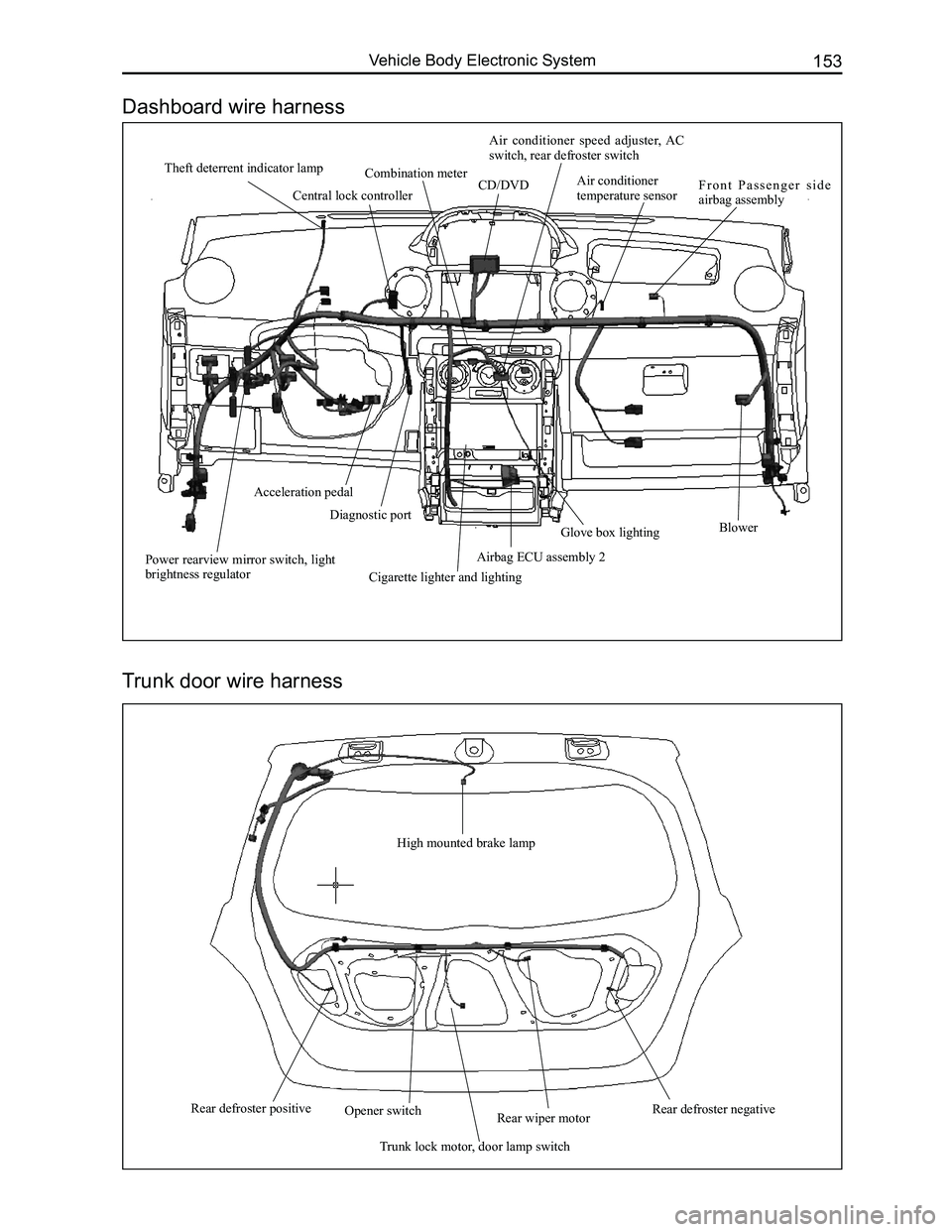
High mounted brake lamp
Rear defroster positiveRear wiper motor
Trunk lock motor, door lamp switch
Opener switchRear defroster negative
Theft deterrent indicator lampCombination meter CD/DVD
Air conditioner speed adjuster, AC switch, rear defroster switch
Air conditioner temperature sensorF r o n t P a s s e n g e r s i d e airbag assembly
BlowerGlove box lighting
Cigarette lighter and lighting
Airbag ECU assembly 2
Diagnostic port
Acceleration pedal
Power rearview mirror switch, light brightness regulator
Trunk door wire harness
Central lock controller
Dashboard wire harness
Page 161 of 281
Downloaded from www.Manualslib.com manuals search engine GWFLORID Maintenance Manual154
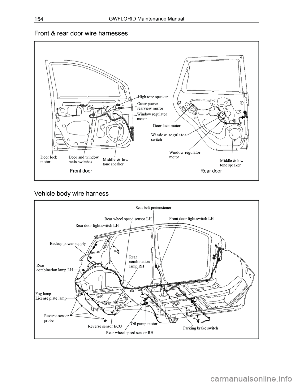
Door lock motorDoor and window main switchesMiddle & low tone speaker
High tone speaker
Outer power rearview mirror
Window regulator motor
Door lock motor
Wi n d o w r e g u l a t o r switch
Window regulator motorMiddle & low tone speaker
Fog lampLicense plate lamp
Rear
combination lamp LH
Rear combination lamp RH
Rear wheel speed sensor RHParking brake switch
Front door light switch LH
Seat belt pretensioner
Rear wheel speed sensor LH
Rear door light switch LH
Backup power supply
Front & rear door wire harnesses
Vehicle body wire harness
Front doorRear door
Reverse sensor ECU
Reverse sensor probeOil pump motor
Page 162 of 281
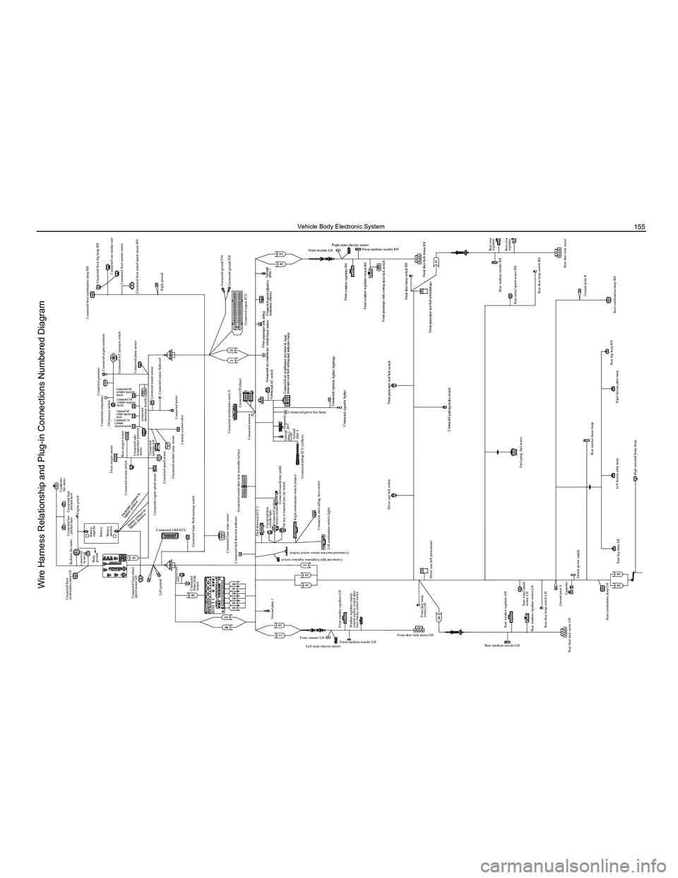
Downloaded from www.Manualslib.com manuals search engine 155Vehicle Body Electronic System
Condenser fan motor
Connected compressor
Oil pressure switch
Front oxygen sensor
Connected reverse switch
Connected engine speed sensor Connected
ignition coil
Connected speed sensor Connected coolant temp. sensor
Canister control valve
Connected combination meter A
Connected antenna
Diagnostic port
Connected AC switch Connected air conditioner temperature sensor
Front passenger side airbag
Connected speed adjustive resistance, blower
Front window regulator RH
Front window regulator switch RH
Front medium woofer RH
Front tweeter LH Right outer electric mirror
Front passenger side central door lock switch
Front door lamp switch RH
Front passenger seat belt pretensioner Front door lock motor RH
Ground
plate 3
Connected cigarette lighter (lighting)
Connected cigarette lighter
Front passenger seat belt switch
Connected parking brake switch Connected air conditioner governor & front
passenger seat belt unfastened indicator lamp
Connected CD player
Connected engine ECUConnected ground P1#
Connected ground P2#
Connected starter
Connected knock sensor
Connected starter field coil
Connected inlet
temperature pressure
sensor
connected
electronic throttle
Rear oxygen sensor
Connected 4th
cylinder injection
nozzle
Connected 3rd
cylinder injection
nozzle
Connected 2nd
cylinder injection
nozzle
Connected 1st
cylinder
injection nozzle
Connected generator
Connected engine armature Connected front combination lamp RH
Connected front fog lamp RH
Connected rear washer motor
Connected front washer motor
Connected front wheel speed sensor RH
Right ground
Connected A/C pressure switch
Connected phase sensor
Connected low
pitched horn
Connected front
combination lamp LH
Rediator fan motor
Connected front
fog lamp LH
Connected high pitched horn
Battery
negative
Body
ground
Battery
Left ground Connected
brake lamp
switch Connected brake fluid warning switch
Connected theft deterrent indicator Theft deterrent ECU 1Connected lock
cylinder lightConnected ignition
switch (white)
The key is inserted into the switch
Right combination switch (wiper) Connected airbag ECU (yellow)Ground
plate 2
Ground
plate 4
Connected accelerator pedal
Ground plate 1
Left outer electric mirror
Front medium woofer LH Front door lock motor LH
Rear medium woofer LH
Rear window regulator switch LH
Rear door lock motor LH Rear door lamp switch LH
Ground point ACapacitor
Vehicle power supply
Rear fog lamp LH Left license plate lamp
High mounted brake lamp
Ground point Trunk opener switch
Trunk motorRear wiper motor
Rear windshield defroster “-”
Trunk lamp switch Right license plate lamp
Rear fog lamp RH
Rear combination lamp RHRear wheel speed sensor RH
Rear window
regulator RH
Rear window
regulator switch RH
Rear door lock motor RH
Rear door lamp switch RH Rear medium woofer RH
Ground point B
Rear combination lamp LH
Rear windshield defroster “+”
Rear wheel speed
sensor LH
Rear window regulator LH
Fuel pump, fuel sensor
Rear interior dome lamp
Front door lamp
switch LH
Driver seat belt pretensioner Driver seat belt switch
Front tweeter LH
Connected light brightness regulator switch
Connected rearview mirror switch (white)
Connected glove box lamp
Front window regulator LH Left combination switch (light)
Connected main airbag, horn switch
Window regulator mainly
control switch, central door
lock mainly control switch Connected central door lock controller (white)
Connected front wiper motor
Connected clutch
switch
Connected ABS ECUBattery
positive
Connected front wheel
speed sensor LH Engine groud
Starter connect to
battery positive
Generator connect to
battery positive
Wire Harness Relationship and Plug-in Connections Numbered Diagram
Page 181 of 281
Downloaded from www.Manualslib.com manuals search engine GWFLORID Maintenance Manual174
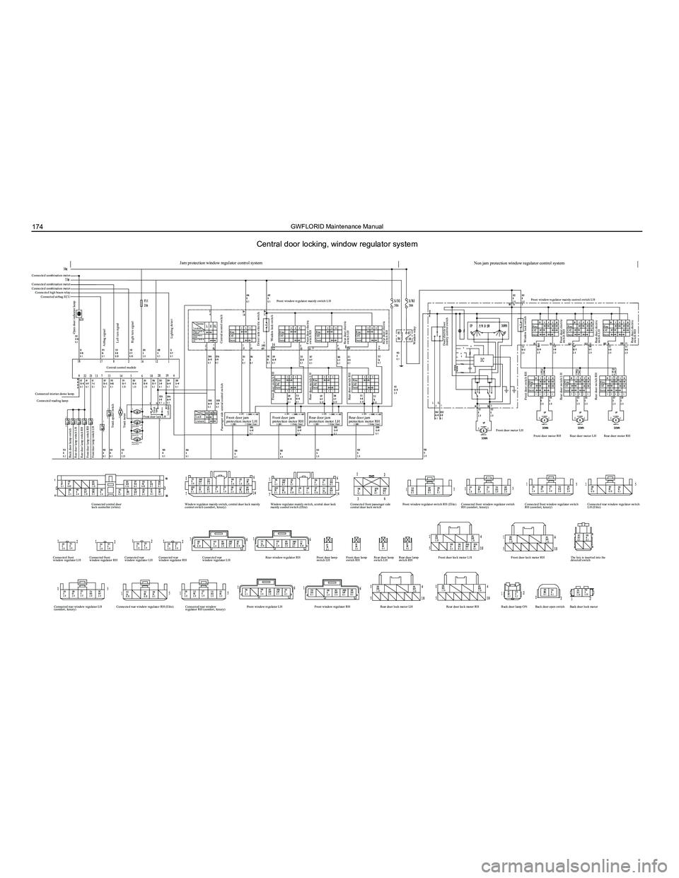
Central door locking, window regulator system
Rise
Off
Descend
Rise
Off
Descend
Rise
Off
Descend
Front door switch RH
Rear door switch LH
Rear door switch RH
Jam protection window regulator control system
Front window regulator mainly switch LH
Front door jam
protection motor LHFront door jam
protection motor RHRear door jam
protection motor LH Rear door jam
protection motor RH
Connected combination meter
Connected combination meter
Connected combination meter
Connected high beam relay
Connected airbag ECU
Central control module
Connected interior dome lamp Connected reading lamp
Open door indicator lamp
Airbag signal
Back door lamp switch
Rear door lamp switch LH
Rear door lamp switch RH
Front door lamp switch RH
Front door lamp switch LH
Trunk opener switch
Trunk motor
Unlock
signal
Lock signalFront door lock LH Lock
UnlockRise
Off
Descend
Rise
Off
Descend
Rise
Off
Descend
Rise
Off
Descend
Rise
Off
Descend
Rise
Off
Descend
Rise
Off
Descend
Rise
Off
Descend
Rise
Off
Descend
Rise
Off
DescendDoor lock is
locked
Stationary
state
Door lock is
on
Front door lock
motor RH
Rear door lock
motor LH
Rear door lock
motor RH
Left turn signal
Right turn signal
Lighting detect
Passenger side central ocntrol switch Central ocntrol switch
Driver side electric switch Window lock switch
Front door electric
switch RH
Rear door electric
switch LH
Rear door electric
switch RH
Window relay
Window lock switch
Front door switch RH
Rear door switch LH
Rear door switch RH Door electric door
mainly control switch
Front door electric
switch RH
Rear door electric
switch LH
Rear door electric
switch RH
Non jam protection window regulator control system
Front door motor LH
Connected central door
lock controller (white)
Connected front
window regulator LH Connected rear window regulator LH
(comfort, luxury) Connected rear window regulator RH (Elite)
Connected rear window
regulator RH (comfort, luxury)Front window regulator LH
Rear door lock motor LHRear door lock motor RHBack door lamp ONBack door open switch Back door lock motor
Front window regulator RH
Connected front
window regulator RH
Connected rear
window regulator LHConnected rear
window regulator RH Connected rear
window regulator LH Rear window regulator RH
Front door lamp
switch LHFront door lamp
switch RHRear door lamp
switch LHRear door lamp
switch RH Front door lock motor LH
Front door lock motor RHThe key is inserted into the
detected switch
Window regulator mainly switch, central door lock mainly
control switch (comfort, luxury) Window regulator mainly switch, central door lock
mainly control switch (Elite)Connected front passenger side
central door lock switchFront window regulator switch RH (Elite)
Connected front window regulator switch
RH (comfort, luxury) Connected front window regulator switch
RH (comfort, luxury)Connected rear window regulator switch
LH (Elite)
Front door motor RH
Rear door motor LHRear door motor RH
Front window regulator mainly control switch LH
Terminal
Location
Terminal
Location