GREAT WALL HOVER 2006 Service Repair Manual
Manufacturer: GREAT WALL, Model Year: 2006, Model line: HOVER, Model: GREAT WALL HOVER 2006Pages: 425, PDF Size: 26.05 MB
Page 221 of 425
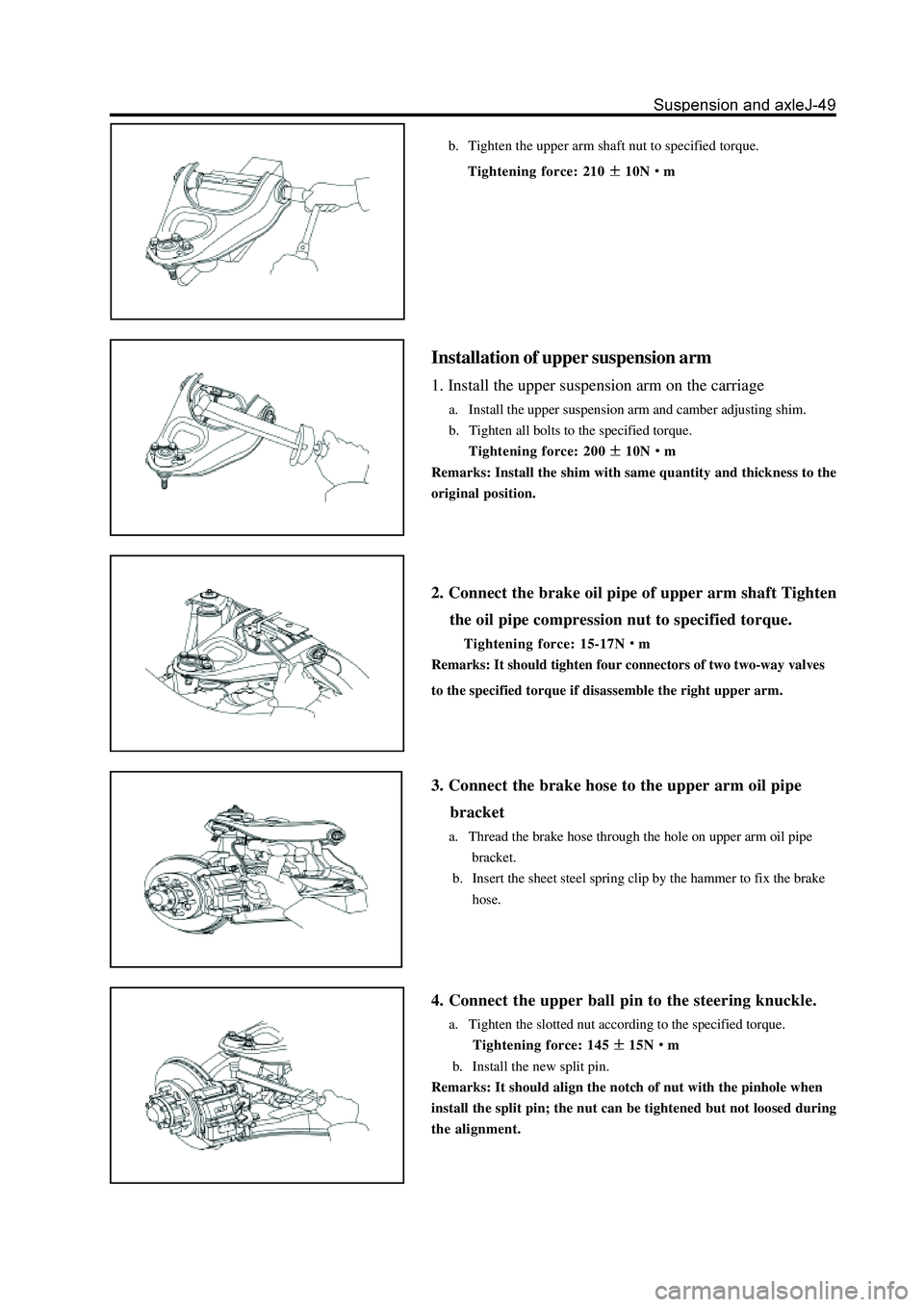
b. Tighten the upper arm shaft nut to specified torque.
Tightening force: 210
10Nm
Installation of upper suspension arm
1. Install the upper suspension arm on the carriage
a. Install the upper suspension arm and camber adjusting shim.
b. Tighten all bolts to the specified torque.
Tightening force: 200
10Nm
Remarks: Install the shim with same quantity and thickness to the
original position.
2. Connect the brake oil pipe of upper arm shaft Tighten
the oil pipe compression nut to specified torque.
Tightening force: 15-17Nm
Remarks: It should tighten four connectors of two two-way valves
to the specified torque if disassemble the right upper arm.
3. Connect the brake hose to the upper arm oil pipe
bracket
a. Thread the brake hose through the hole on upper arm oil pipe
bracket.
b. Insert the sheet steel spring clip by the hammer to fix the brake
hose.
4. Connect the upper ball pin to the steering knuckle.
a. Tighten the slotted nut according to the specified torque.
Tightening force: 145
15Nm
b. Install the new split pin.
Remarks: It should align the notch of nut with the pinhole when
install the split pin; the nut can be tightened but not loosed during
the alignment.
Page 222 of 425
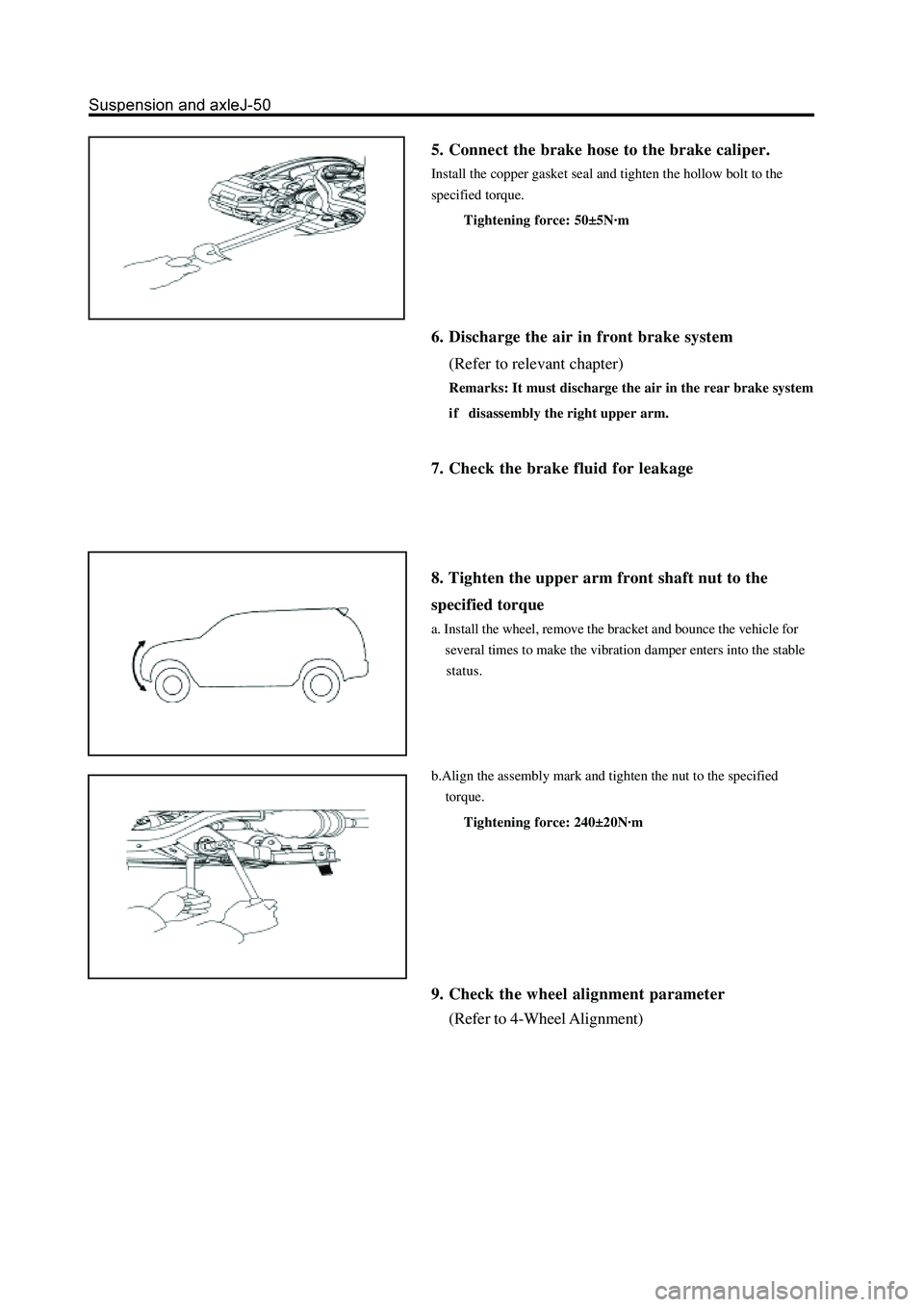
5. Connect the brake hose to the brake caliper.
Install the copper gasket seal and tighten the hollow bolt to the
specified torque.
Tightening force: 50±5N·m
6. Discharge the air in front brake system
(Refer to relevant chapter)
Remarks: It must discharge the air in the rear brake system
i f disassembly the right upper arm.
7. Check the brake fluid for leakage
8. Tighten the upper arm front shaft nut to the
specified torque
a. Install the wheel, remove the bracket and bounce the vehicle for
several times to make the vibration damper enters into the stable
status.
b.Align the assembly mark and tighten the nut to the specified
torque.
Tightening force: 240±20N·m
9. Check the wheel alignment parameter
(Refer to 4-Wheel Alignment)
Page 223 of 425
Stabilizer bar
Disassembly of stabilizer bar
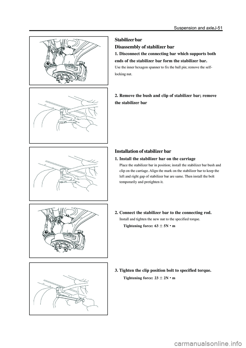
1. Disconnect the connecting bar which supports both
ends of the stabilizer bar form the stabilizer bar.
Use the inner hexagon spanner to fix the ball pin; remove the self-
locking nut.
2. Remove the bush and clip of stabilizer bar; remove
the stabilizer bar
Installation of stabilizer bar
1. Install the stabilizer bar on the carriage
Place the stabilizer bar in position; install the stabilizer bar bush and
clip on the carriage. Align the mark on the stabilizer bar to keep the
left and right gap of stabilizer bar are same. Then install the bolt
temporarily and pretighten it.
2. Connect the stabilizer bar to the connecting rod.
Install and tighten the new nut to the specified torque.
Tightening force: 63
5Nm
3. Tighten the clip position bolt to specified torque.
Tightening force: 232Nm
Page 224 of 425
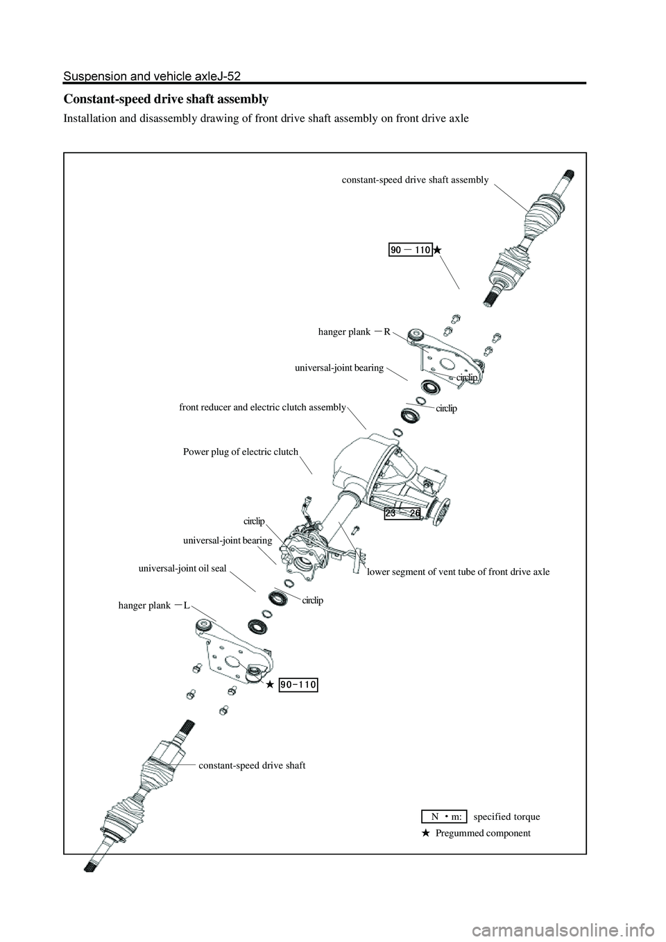
Constant-speed drive shaft assembly
Installation and disassembly drawing of front drive shaft assembly on front drive axle
hanger plank R
universal-joint bearing
front reducer and electric clutch assembly
Power plug of electric clutch
circlip
hanger plank L
constant-speed drive shaft
circlip
lower segment of vent tube of front drive axle
circlip
circlip
Pregummed component
N m: specified torque
universal-joint oil sealuniversal-joint bearingconstant-speed drive shaft assembly
Page 225 of 425
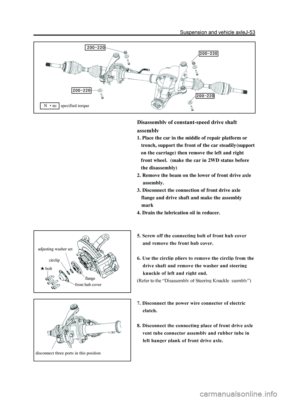
1. Place the car in the middle of repair platform or
trench, support the front of the car steadily(support
on the carriage) then remove the left and right
front wheel. (make the car in 2WD status before
the disassembly)
2. Remove the beam on the lower of front drive axle
assembly.
3. Disconnect the connection of front drive axle
flange and drive shaft and make the assembly
mark
4. Drain the lubrication oil in reducer.
bolt
front hub cover
circlip
adjusting washer set
flange
disconnect three ports in this position
N m: specified torque
Page 226 of 425
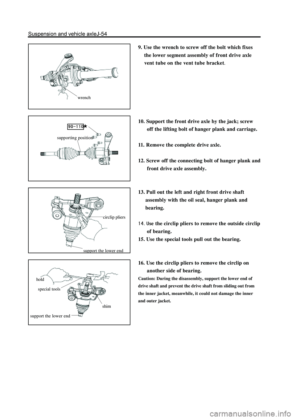
9. Use the wrench to screw off the bolt which fixes
the lower segment assembly of front drive axle
vent tube on the vent tube bracket.
10. Support the front drive axle by the jack; screw
off the lifting bolt of hanger plank and carriage.
11. Remove the complete drive axle.
12. Screw off the connecting bolt of hanger plank and
front drive axle assembly.
13. Pull out the left and right front drive shaft
assembly with the oil seal, hanger plank and
bearing.
se the circlip pliers to remove the outside circlip
of bearing.
15. Use the special tools pull out the bearing.
16. Use the circlip pliers to remove the circlip on
another side of bearing.
Caution: During the disassembly, support the lower end of
drive shaft and prevent the drive shaft from sliding out from
the inner jacket, meanwhile, it could not damage the inner
and outer jacket.
wrench
circlip pliers
support the lower end
hold
special tools
shim
support the lower end
supporting position
Page 227 of 425
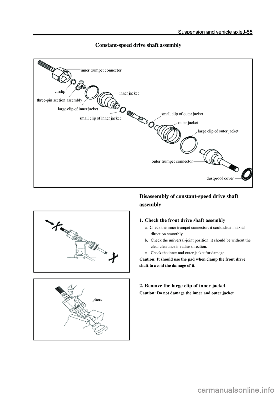
Constant-speed drive shaft assembly
pliers
Disassembly of constant-speed drive shaft
assembly
1. Check the front drive shaft assembly
a. Check the inner trumpet connector; it could slide in axial
direction smoothly.
b. Check the universal-joint position; it should be without the
clear clearance in radius direction.
c. Check the inner and outer jacket for damage.
Caution: It should use the pad when clamp the front drive
shaft to avoid the damage of it.
2. Remove the large clip of inner jacket
Caution: Do not damage the inner and outer jacket
inner trumpet connector
circlip
three-pin section assembly
large clip of inner jacket
inner jacket
small clip of inner jacketsmall clip of outer jacket
outer jacket
large clip of outer jacket
outer trumpet connector
dustproof cover
Page 228 of 425
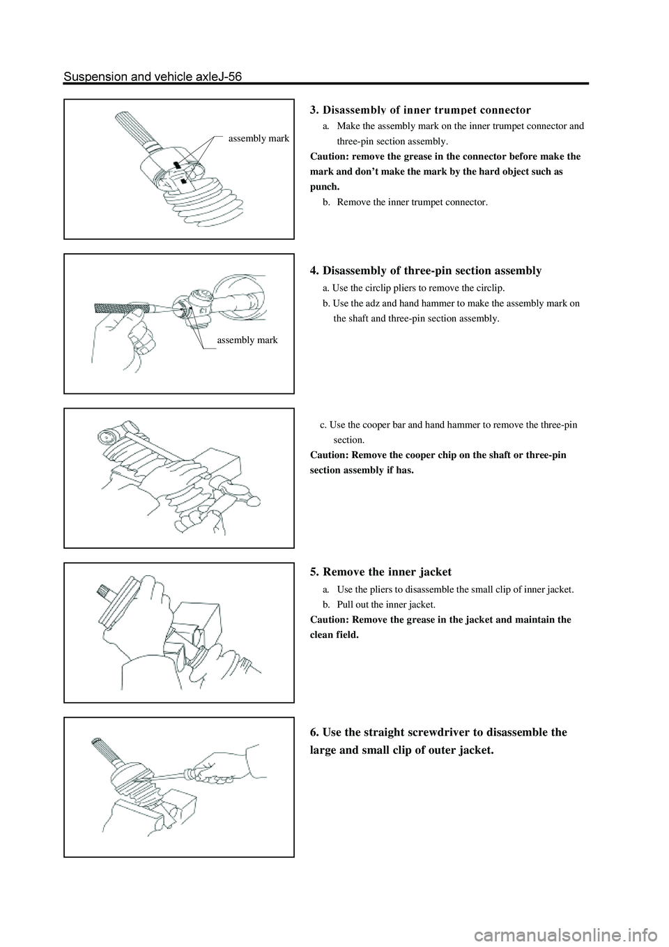
a. Make the assembly mark on the inner trumpet connector and
three-pin section assembly.
Caution: remove the grease in the connector before make the
mark and don’t make the mark by the hard object such as
punch.
b. Remove the inner trumpet connector.
4. Disassembly of three-pin section assembly
a. Use the circlip pliers to remove the circlip.
b. Use the adz and hand hammer to make the assembly mark on
the shaft and three-pin section assembly.
c. Use the cooper bar and hand hammer to remove the three-pin
section.
Caution: Remove the cooper chip on the shaft or three-pin
section assembly if has.
5. Remove the inner jacket
a. Use the pliers to disassemble the small clip of inner jacket.
b. Pull out the inner jacket.
Caution: Remove the grease in the jacket and maintain the
clean field.
6. Use the straight screwdriver to disassemble the
large and small clip of outer jacket.
assembly mark
assembly mark
Page 229 of 425
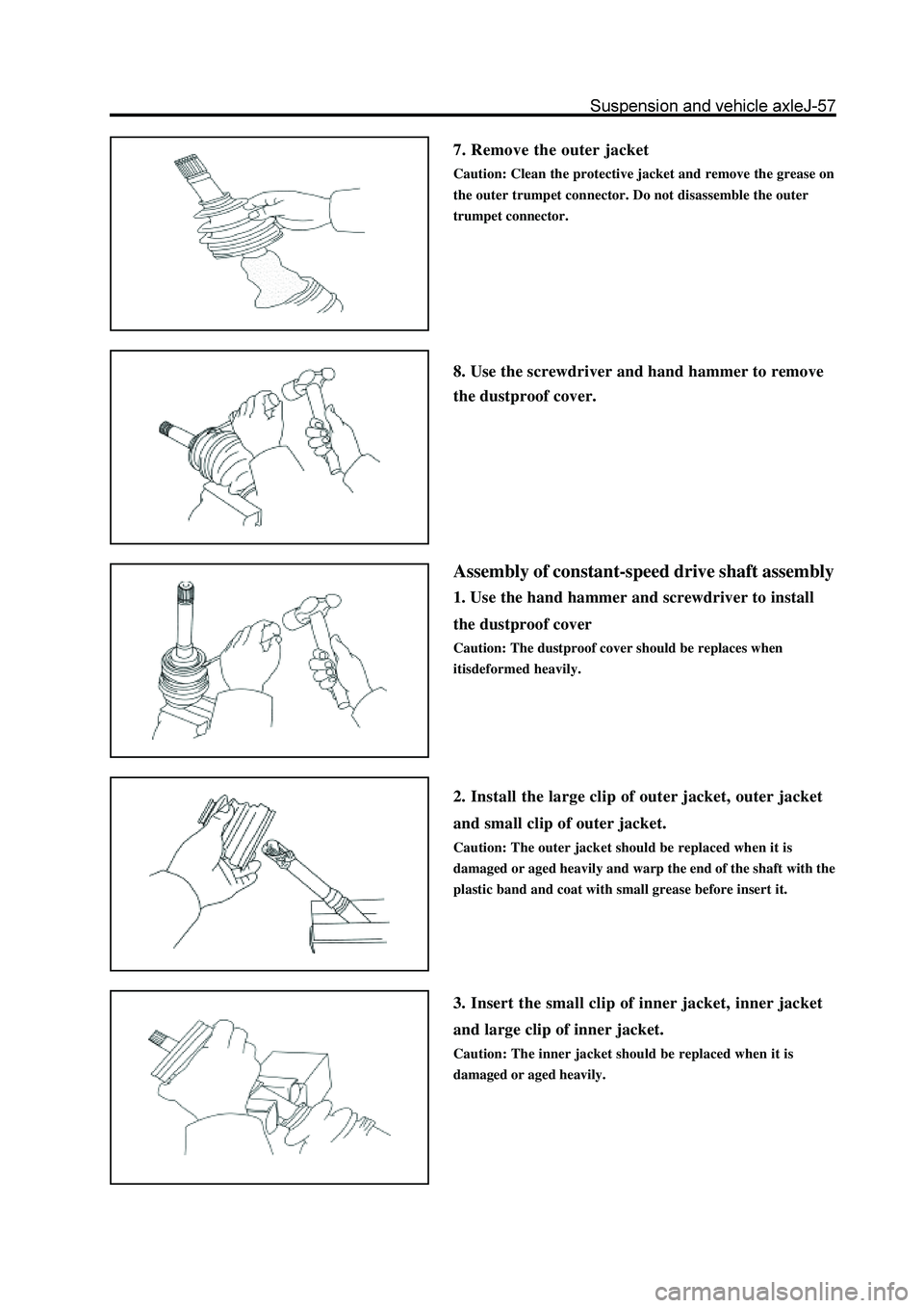
7. Remove the outer jacket
Caution: Clean the protective jacket and remove the grease on
the outer trumpet connector. Do not disassemble the outer
trumpet connector.
8. Use the screwdriver and hand hammer to remove
the dustproof cover.
Assembly of constant-speed drive shaft assembly
1. Use the hand hammer and screwdriver to install
the dustproof cover
Caution: The dustproof cover should be replaces when
itisdeformed heavily.
2. Install the large clip of outer jacket, outer jacket
and small clip of outer jacket.
Caution: The outer jacket should be replaced when it is
damaged or aged heavily and warp the end of the shaft with the
plastic band and coat with small grease before insert it.
3. Insert the small clip of inner jacket, inner jacket
and large clip of inner jacket.
Caution: The inner jacket should be replaced when it is
damaged or aged heavily.
Page 230 of 425
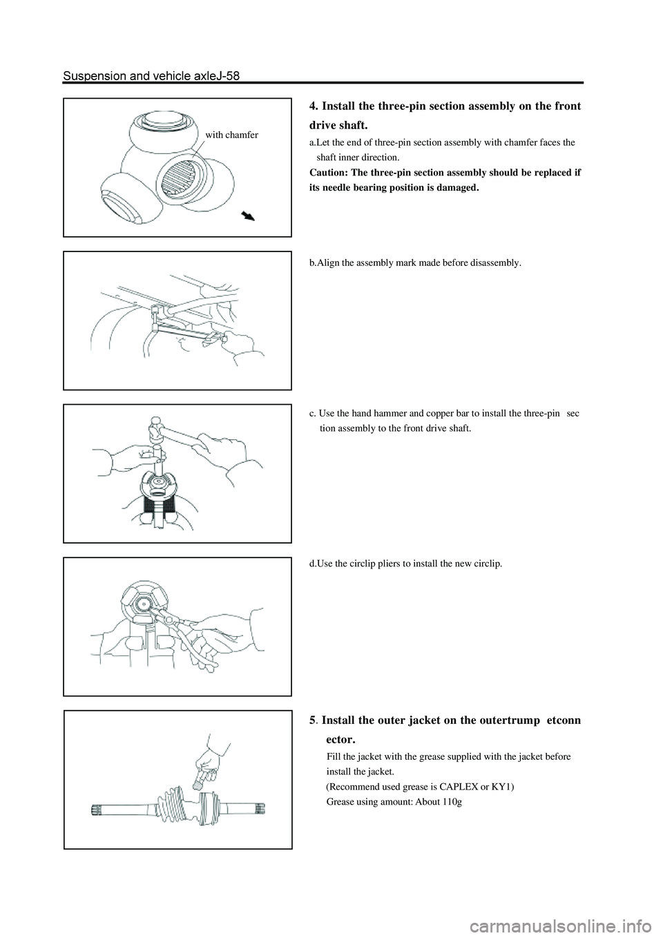
4. Install the three-pin section assembly on the front
drive shaft.
a.Let the end of three-pin section assembly with chamfer faces the
shaft inner direction.
Caution: The three-pin section assembly should be replaced if
its needle bearing position is damaged.
b.Align the assembly mark made before disassembly.
c. Use the hand hammer and copper bar to install the three-pin sec
tion assembly to the front drive shaft.
d.Use the circlip pliers to install the new circlip.
5Install the outer jacket on the outertrump etconn
ector.
Fill the jacket with the grease supplied with the jacket before
install the jacket.
(Recommend used grease is CAPLEX or KY1)
Grease using amount: About 110g
with chamfer