GREAT WALL HOVER 2006 Service Repair Manual
Manufacturer: GREAT WALL, Model Year: 2006, Model line: HOVER, Model: GREAT WALL HOVER 2006Pages: 425, PDF Size: 26.05 MB
Page 301 of 425
Brake-15
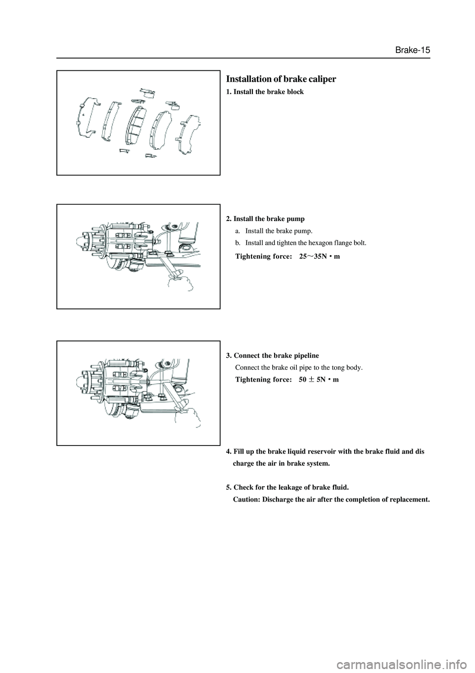
Installation of brake caliper
1. Install the brake block
2. Install the brake pump
a. Install the brake pump.
b. Install and tighten the hexagon flange bolt.
Tightening force: 25
35Nm
3. Connect the brake pipeline
Connect the brake oil pipe to the tong body.
Tightening force: 50
5Nm
4. Fill up the brake liquid reservoir with the brake fluid and dis
charge the air in brake system.
5. Check for the leakage of brake fluid.
Caution: Discharge the air after the completion of replacement.
Page 302 of 425
Brake-16
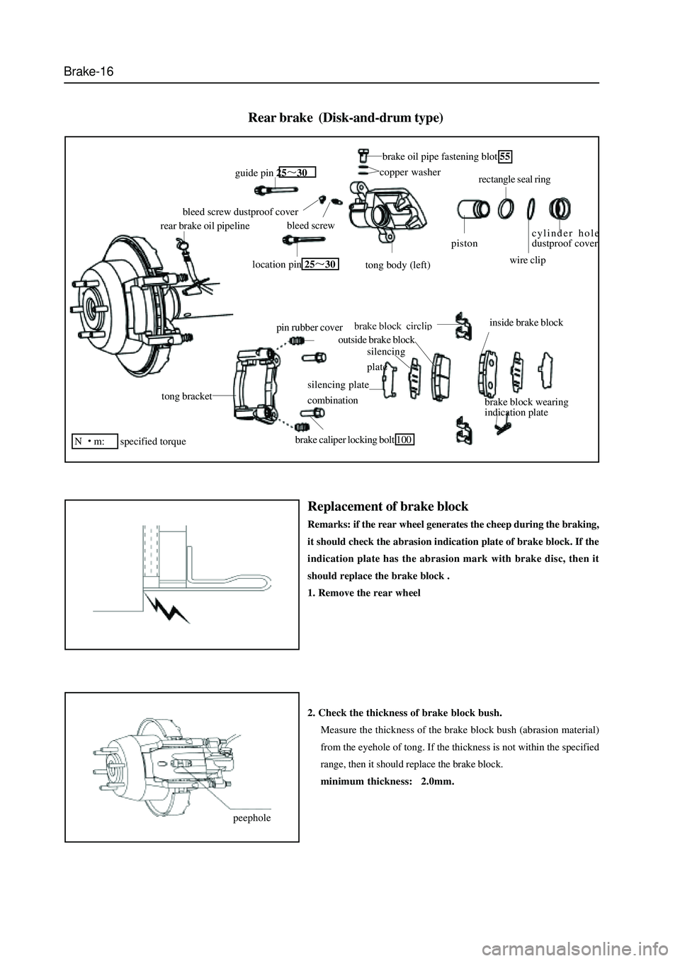
Rear brake (Disk-and-drum type)
tong bracket
pin rubber cover
brake caliper locking bolt 100
silencing plate
combination
outside brake block
inside brake block
brake block wearing
indication plate
cylinder hole
dustproof cover
wire clip
rectangle seal ring
piston
tong body (left)
copper washer
brake oil pipe fastening blot 55
location pin 2530
bleed screw
bleed screw dustproof cover
guide pin 2530
rear brake oil pipeline
N
m: specified torque
peepholesilencing
plate
Replacement of brake block
Remarks: if the rear wheel generates the cheep during the braking,
it should check the abrasion indication plate of brake block. If the
indication plate has the abrasion mark with brake disc, then it
should replace the brake block .
1. Remove the rear wheel
2. Check the thickness of brake block bush.
Measure the thickness of the brake block bush (abrasion material)
from the eyehole of tong. If the thickness is not within the specified
range, then it should replace the brake block.
minimum thickness: 2.0mm.
Page 303 of 425
Brake-17
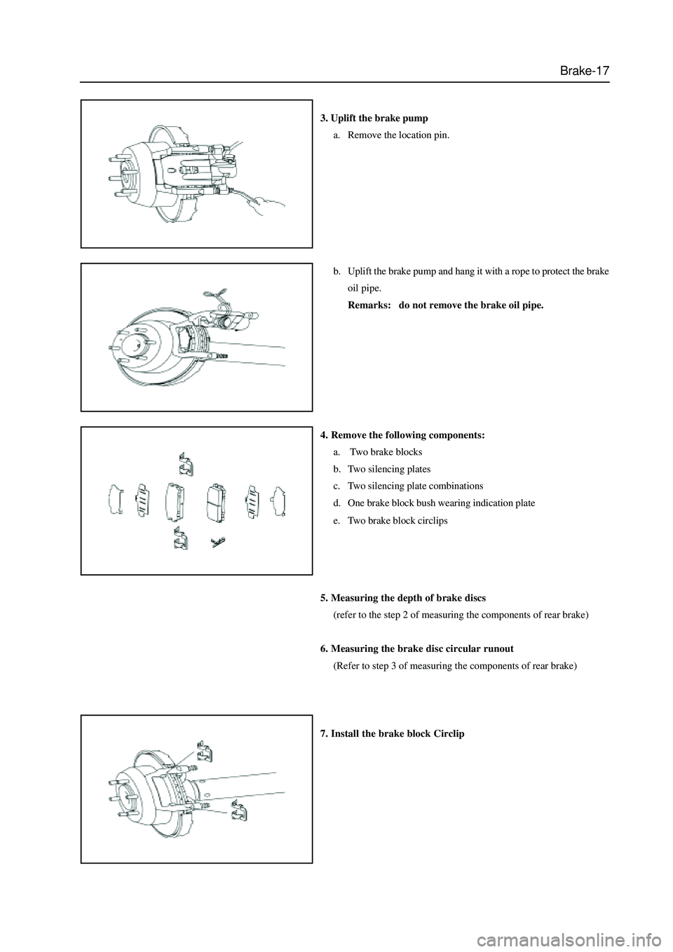
3. Uplift the brake pump
a. Remove the location pin.
b. Uplift the brake pump and hang it with a rope to protect the brake
oil pipe.
Remarks: do not remove the brake oil pipe.
4. Remove the following components:
a. Two brake blocks
b. Two silencing plates
c. Two silencing plate combinations
d. One brake block bush wearing indication plate
e. Two brake block circlips
5. Measuring the depth of brake discs
(refer to the step 2 of measuring the components of rear brake)
6. Measuring the brake disc circular runout
(Refer to step 3 of measuring the components of rear brake)
7. Install the brake block Circlip
Page 304 of 425
Brake-18
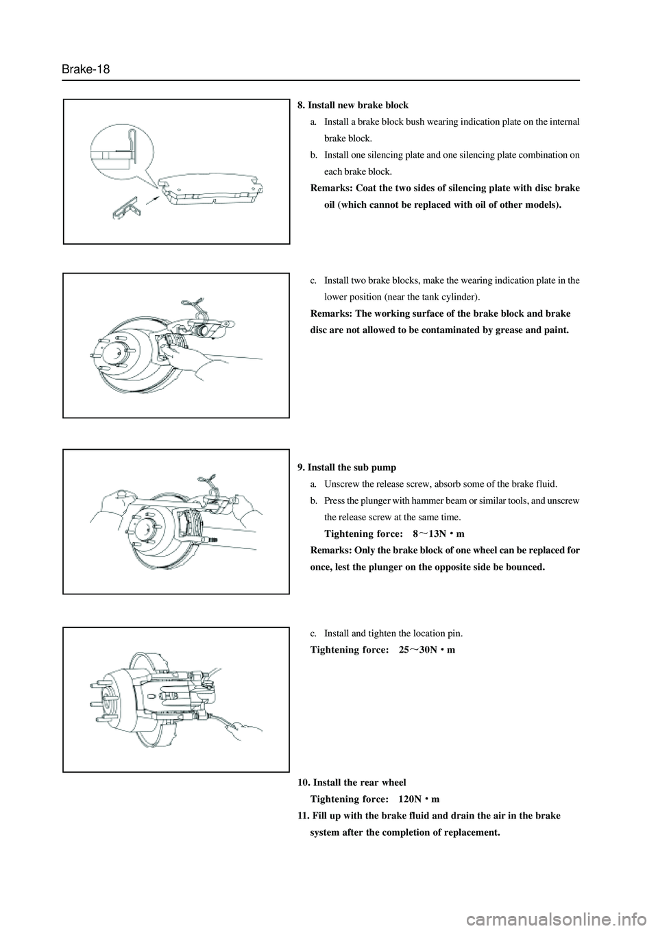
8. Install new brake block
a. Install a brake block bush wearing indication plate on the internal
brake block.
b. Install one silencing plate and one silencing plate combination on
each brake block.
Remarks: Coat the two sides of silencing plate with disc brake
oil (which cannot be replaced with oil of other models).
c. Install two brake blocks, make the wearing indication plate in the
lower position (near the tank cylinder).
Remarks: The working surface of the brake block and brake
disc are not allowed to be contaminated by grease and paint.
9. Install the sub pump
a. Unscrew the release screw, absorb some of the brake fluid.
b. Press the plunger with hammer beam or similar tools, and unscrew
the release screw at the same time.
Tightening force: 8
13Nm
Remarks: Only the brake block of one wheel can be replaced for
once, lest the plunger on the opposite side be bounced.
c. Install and tighten the location pin.
Tightening force: 25
30Nm
10. Install the rear wheel
Tightening force: 120N
m
11. Fill up with the brake fluid and drain the air in the brake
system after the completion of replacement.
Page 305 of 425
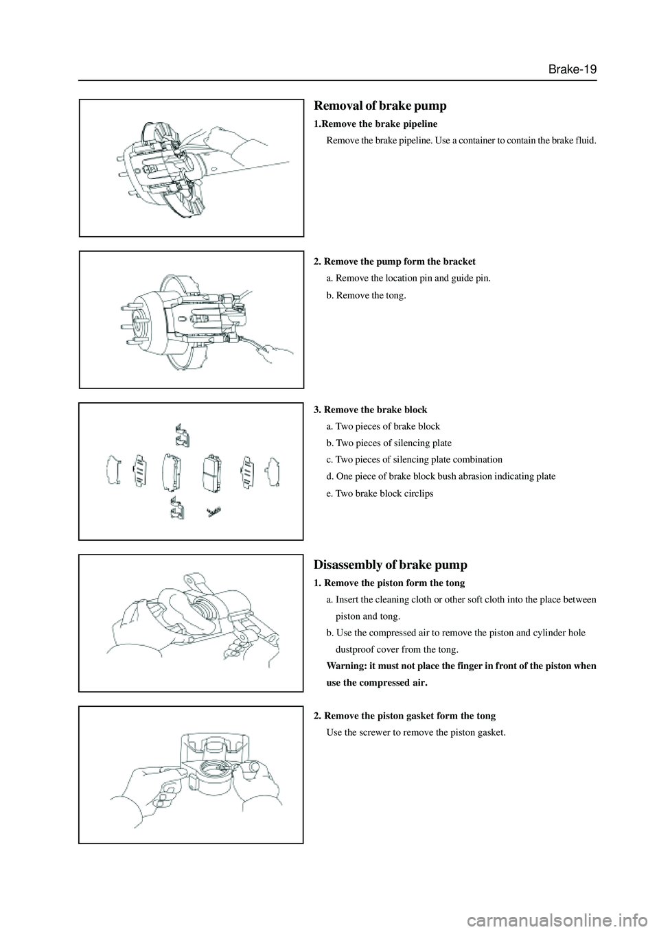
Brake-19
Removal of brake pump
1.Remove the brake pipeline
Remove the brake pipeline. Use a container to contain the brake fluid.
2. Remove the pump form the bracket
a. Remove the location pin and guide pin.
b. Remove the tong.
3. Remove the brake block
a. Two pieces of brake block
b. Two pieces of silencing plate
c. Two pieces of silencing plate combination
d. One piece of brake block bush abrasion indicating plate
e. Two brake block circlips
Disassembly of brake pump
1. Remove the piston form the tong
a. Insert the cleaning cloth or other soft cloth into the place between
piston and tong.
b. Use the compressed air to remove the piston and cylinder hole
dustproof cover from the tong.
Warning: it must not place the finger in front of the piston when
use the compressed air.
2. Remove the piston gasket form the tong
Use the screwer to remove the piston gasket.
Page 306 of 425
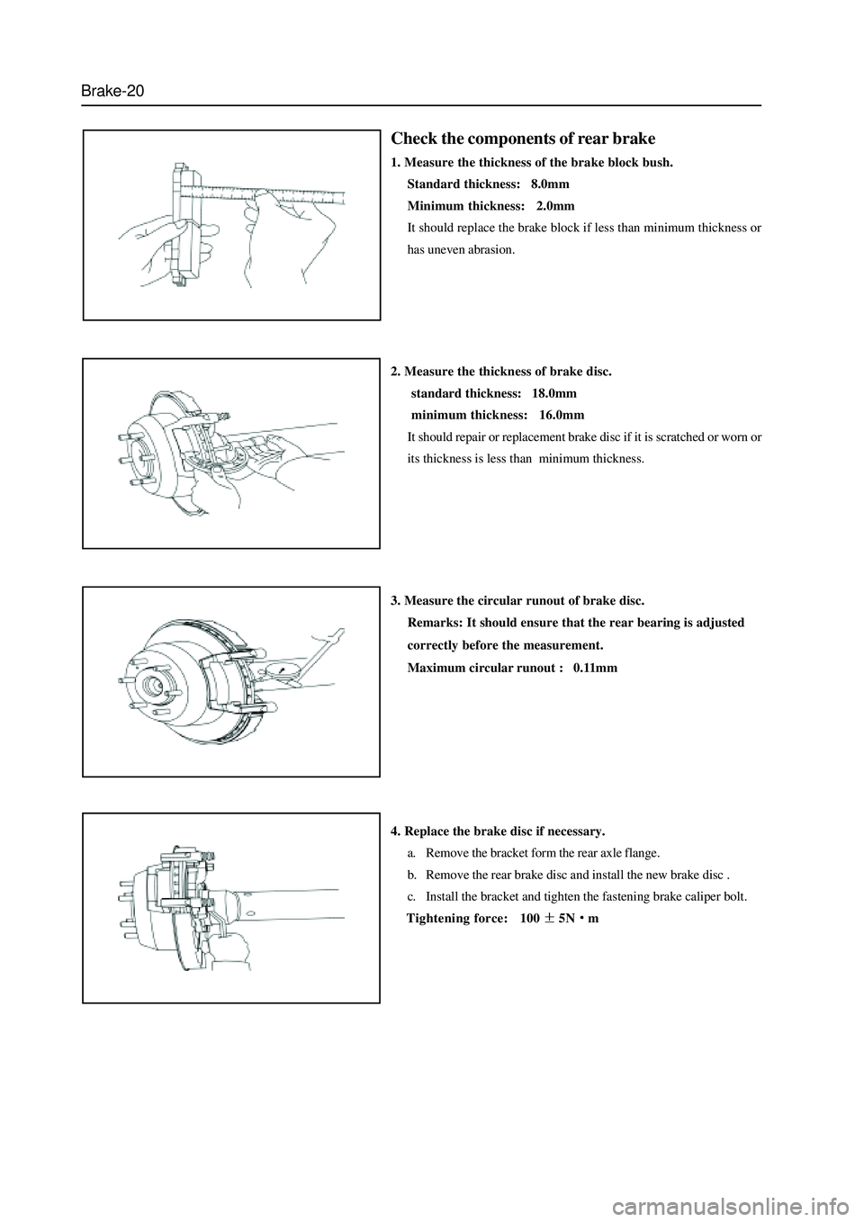
Brake-20
Check the components of rear brake
1. Measure the thickness of the brake block bush.
Standard thickness: 8.0mm
Minimum thickness: 2.0mm
It should replace the brake block if less than minimum thickness or
has uneven abrasion.
2. Measure the thickness of brake disc.
standard thickness: 18.0mm
minimum thickness: 16.0mm
It should repair or replacement brake disc if it is scratched or worn or
its thickness is less than minimum thickness.
3. Measure the circular runout of brake disc.
Remarks: It should ensure that the rear bearing is adjusted
correctly before the measurement.
Maximum circular runout : 0.11mm
4. Replace the brake disc if necessary.
a. Remove the bracket form the rear axle flange.
b. Remove the rear brake disc and install the new brake disc .
c. Install the bracket and tighten the fastening brake caliper bolt.
Tightening force: 100
5Nm
Page 307 of 425
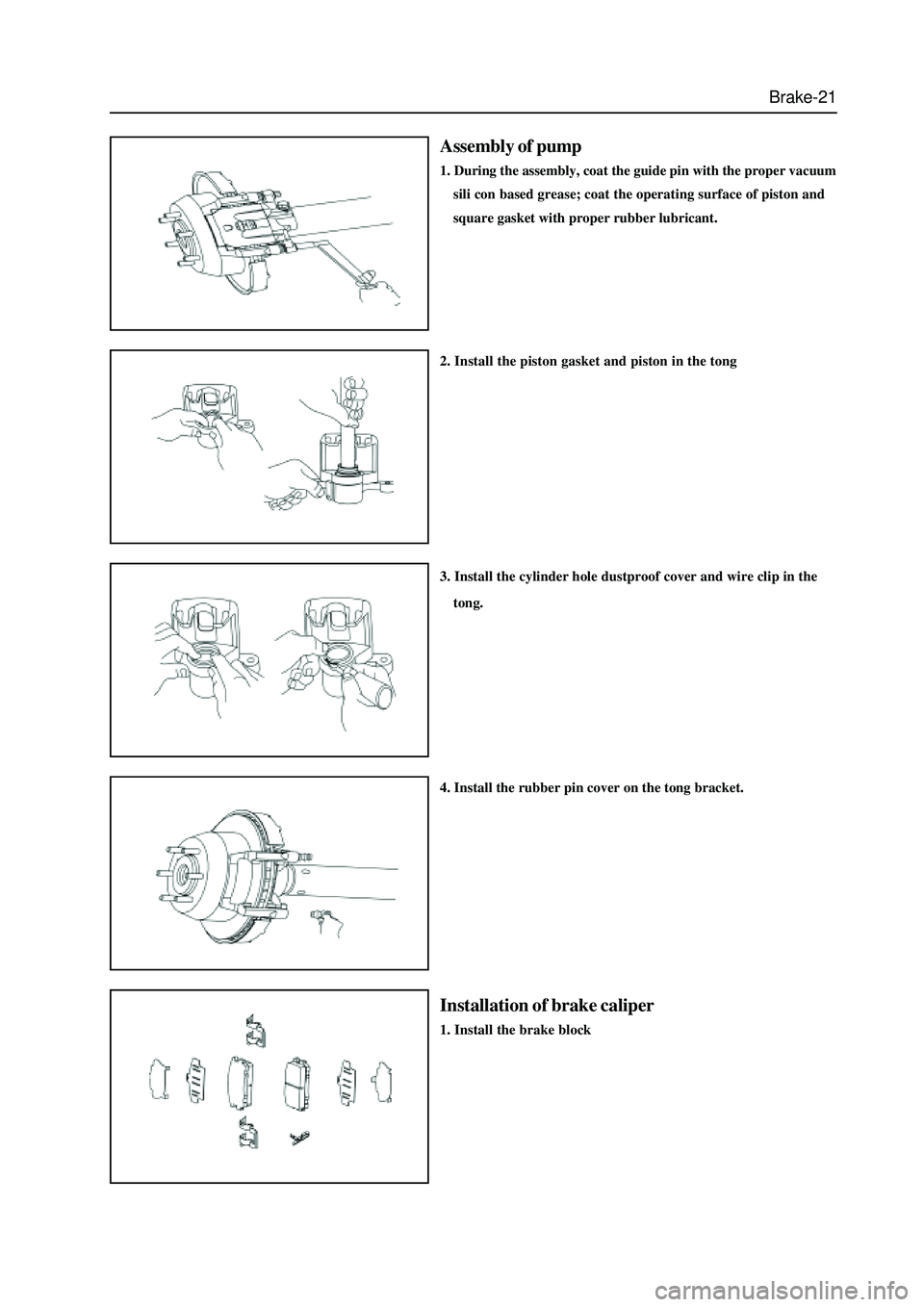
Brake-21
Assembly of pump
1. During the assembly, coat the guide pin with the proper vacuum
sili con based grease; coat the operating surface of piston and
square gasket with proper rubber lubricant.
2. Install the piston gasket and piston in the tong
3. Install the cylinder hole dustproof cover and wire clip in the
tong.
4. Install the rubber pin cover on the tong bracket.
Installation of brake caliper
1. Install the brake block
Page 308 of 425
Brake-22
2. Install the piston gasket in the tong body.
a. Screw the bleed screw into the bleed hole;
b. Install the square gasket in the sealing groove of two cylinders of
pump respectively after coat its working surface with proper
rubber lubricant.
Tightening torque 7
10Nm.
3. Connect the brake pipeline
Connect the brake oil pipe to the tong.
Tightening force: 50
5Nm
4. Fill up the brake system with the brake fluid and drain the air
in the brake system.
5. Check for leakage of brake fluid.
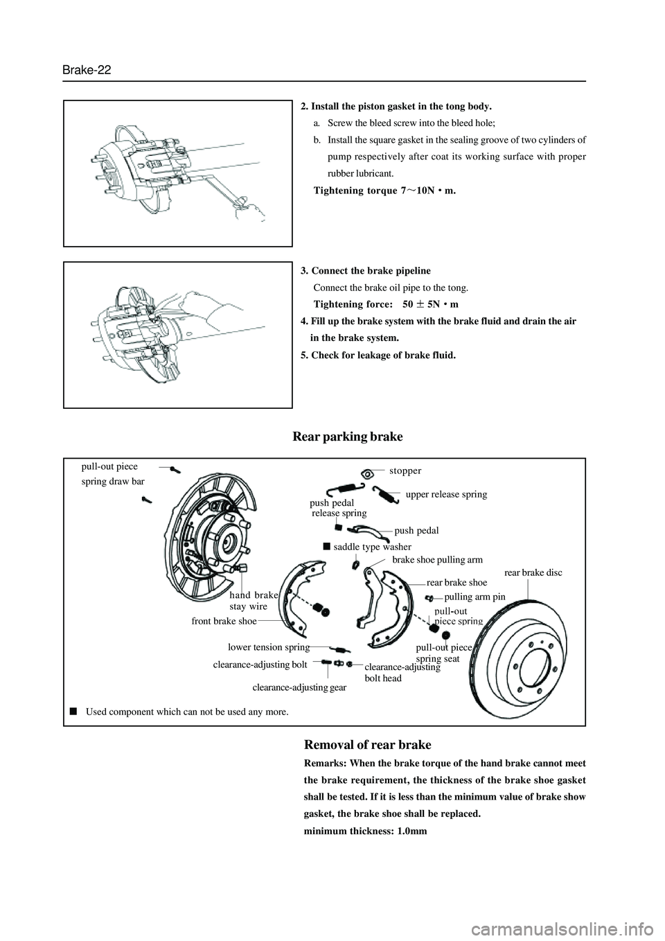
Rear parking brake
pull-out piece
spring draw bar
hand brake
stay wire
front brake shoe
lower tension spring
clearance-adjusting bolt
clearance-adjusting gear
clearance-adjusting
bolt head
pull-out piece
spring seat
pulling arm pin
rear brake shoe
brake shoe pulling arm
saddle type washer
push pedal
push pedal
release spring
stopper
upper release spring
rear brake disc
Used component which can not be used any more.
Removal of rear brake
Remarks: When the brake torque of the hand brake cannot meet
the brake requirement, the thickness of the brake shoe gasket
shall be tested. If it is less than the minimum value of brake show
gasket, the brake shoe shall be replaced.
minimum thickness: 1.0mm
Page 309 of 425
Brake-23
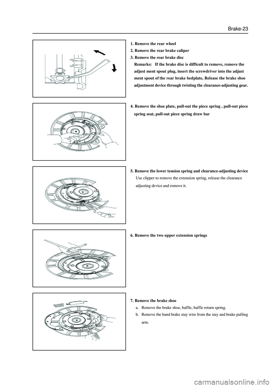
1. Remove the rear wheel
2. Remove the rear brake caliper
3. Remove the rear brake disc
Remarks: If the brake disc is difficult to remove, remove the
adjust ment spout plug, insert the screwdriver into the adjust
ment spout of the rear brake bedplate, Release the brake shoe
adjustment device through twisting the clearance-adjusting gear.
4. Remove the shoe plate, pull-out the piece spring , pull-out piece
spring seat, pull-out piece spring draw bar
5. Remove the lower tension spring and clearance-adjusting device
Use clipper to remove the extension spring, release the clearance
adjusting device and remove it.
6. Remove the two upper extension springs
7. Remove the brake shoe
a. Remove the brake shoe, baffle, baffle return spring.
b. Remove the band brake stay wire from the stay and brake pulling
arm.
Page 310 of 425
Brake-24
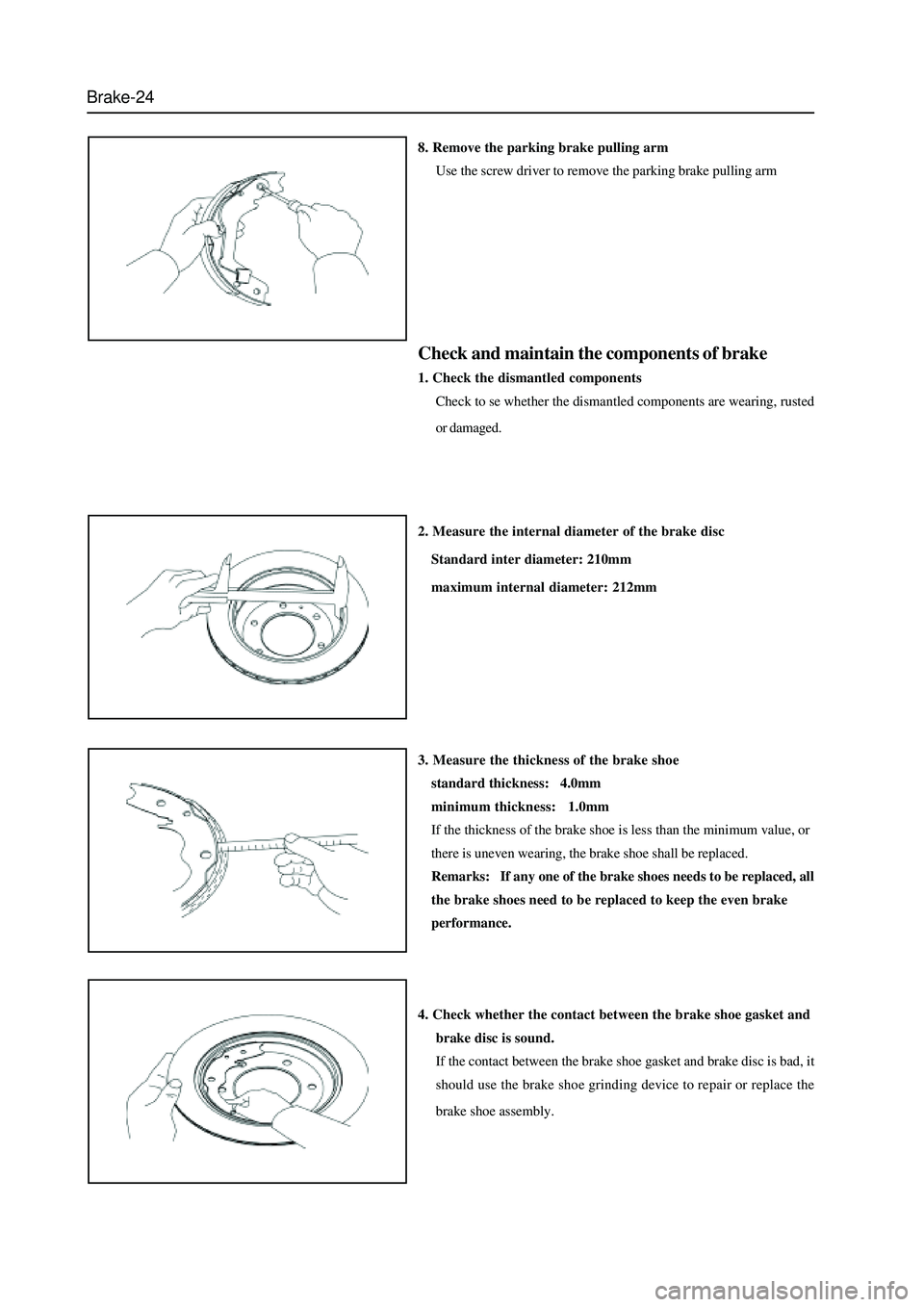
8. Remove the parking brake pulling arm
Use the screw driver to remove the parking brake pulling arm
Check and maintain the components of brake
1. Check the dismantled components
Check to se whether the dismantled components are wearing, rusted
or damaged.
2. Measure the internal diameter of the brake disc
Standard inter diameter: 210mm
maximum internal diameter: 212mm
3. Measure the thickness of the brake shoe
standard thickness: 4.0mm
minimum thickness: 1.0mm
If the thickness of the brake shoe is less than the minimum value, or
there is uneven wearing, the brake shoe shall be replaced.
Remarks: If any one of the brake shoes needs to be replaced, all
the brake shoes need to be replaced to keep the even brake
performance.
4. Check whether the contact between the brake shoe gasket and
brake disc is sound.
If the contact between the brake shoe gasket and brake disc is bad, it
should use the brake shoe grinding device to repair or replace the
brake shoe assembly.