mat HONDA CIVIC 1999 6.G Workshop Manual
[x] Cancel search | Manufacturer: HONDA, Model Year: 1999, Model line: CIVIC, Model: HONDA CIVIC 1999 6.GPages: 2189, PDF Size: 69.39 MB
Page 1195 of 2189
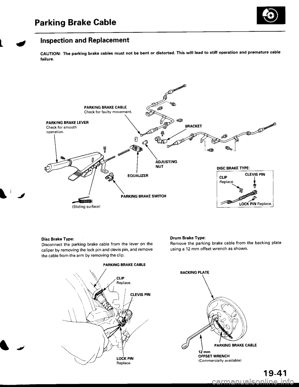
Parking Brake Cable
LInspection and Replacement
CAUTION: The parking blake cables must not be bent or distorted. This will lead to stiff operation and premature cable
failure.
PARKING BRAKE CABLECheck for faulty movement.
PARKING BRAKE LEVERCheck for smoothoperation.
\i ,
EOUALIZER
PARKING BRAKE SWITCH
Disc Brake Type:
Disconnect the parking brake cable from the lever on the
caliper by removing the lock pin and clevis pin, and remove
the cable from the arm by removing the clip
CLEVIS PIN
Drum Brake Type:
Remove the parking brake cable from the backing plate
using a 12 mm offset wrench as shown.
12 mmOFFSET WRENCH(Commercially available)
DISC BRAKE TYPE:
CLEVIS PIN
PARKING ERAKE CABLE
{tt
BACKING PLATE
/
19-41
Page 1200 of 2189
t-Operation
t
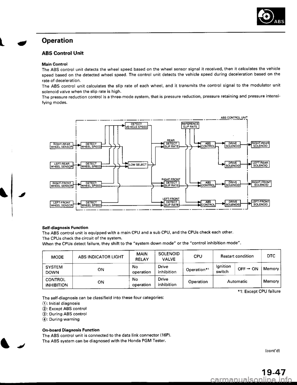
ABS Control Unit
Main Control
The ABS control unit detects the wheel speed based on the wheel sensor signal it received, then it calculates the vehicle
speed based on the detected wheel speed. The control unit detects the vehicle speed during deceleration based on the
rate of deceleration.
The ABS control unit calculates the slip rate of each wheel. and it transmits the control signal to the modulator unit
solenoid valve when the slip rate is high.
The pressure reduction control is a three-mode system, that is pressure reduction, pressure retaining and pressure intensi-
fying modes.
Self -diagnosis Funqtion
The ABS control unit is equipped with a main CPU and a sub CPU, and the CPUS check each other'
The CPUs check the circuit of the svstem.
When the CPUS detect failure, they shift to the "system down mode" or the "control inhibition mode"
The self-diagnosis can be classifield into these four categories:
O: Initial diagnosis
@: Except ABS control
@: During ABS control
@: During warning
On-board Diagnosis Funstion
The ABS control unit is connected to the data link connector {16P).
The ABS system can be diagnosed with the Honda PGM Tester.
(cont'd)
MODEABS INDICATOR LIGHTMAIN
RELAY
SOLENOID
VALVECPURestart conditionDTC
SYSTE IV
DOWNONNo
operation
Drive
inhibitionOperation*rlgnition
switchOFF + ONMemory
CONTROL
INHIBITIONONNo
operalron
Drive
inhibitionOperationAutomaticMemory
*1: Except CPU failure
/
19-47
Page 1207 of 2189
Troubleshooting Precautions
ABS Indicator Light
I The ABS indicator light comes on when the ABS control unit detects a problem in the system. However, even thoughthe system is normal, the ABs indicator light can come on, too, under the following conditions. To determine theactual cause of the problem, question the customer about the problem, taking the following conditions into consider-ation.
. Signal disturbance
. Wheel soin
. Only drive wheels rotate. Battery voltage fluctuates
2. When a problem is detected and the ABS indicator light comes on, the indicator light can stay on untat the ignitionswitch is turned off, or it can automatically go off, depending on the mode.. Lightstayson until the ignition switch isturned off;When the system is inthesvstem down mode.o Light automatically goes off:When the system is in the control inhibition mode.(refer to symptom-to-system chart)3 The ABS indicator light stays on when the system is reactivated without erasing the DTC, but it goes off after startingthe car.
when the wheel sensor system is faulty and the ABS indicator light comes on, the algorithm of the system automaticallyturns off the ABS indicator light after the wheel speed signal returns to the normal speed. while, when the DTC is erased,the CPU is reset and the ABS indicator light goes off when the system check€d out normal by the initial diagnosis.Therefore, test-drive the car after servicing the wheel sensor system, and be sure that the ABS indicator light does notcome on.
4. When the ABS control unit outputs battery voltage to the gauge assembty, the ABS indicator light goes off.
Diagnostic Trouble Code (DTC)
1. The diagnostic trouble code (DTC) is memorized when a problem is detected and the ABS indicator light does not gooff, or when the ABS indicator light comes on.The DTC is not memorized when the ABs indicator right comes on unress the cpU is activated.2. The memory can hold any number of DTCs. However, when the same DTc is detected twice or more, the later one iswritten over the old one.
Therefore. when the same problem is detected repeatedly, it is recorded as one DTC.3. The DTCS are indicated in the order of ascending number, not in the order thev occur.4. The DTCS are memorized in the EEpROM {non-volatile memorv}.Therefore, the memorized DTCS cannot be canceled by disconnecting the battery. perform the specified orocedures toerase.
Solf-diagnosis
1. The self-diagnosis can be classifield into these four categories:' Initial diagnosis; Performed right after the engine sta rts and untiltheABs indicator light goes off.o Except ABS control: Performed when the ABS is not functioning,. During ABS control: Performed when the ABS is functioning.. During warning: Performed when the ABS indicator light is ON.2 The system performs the following controls when a problem is detected by the self-diagnosis:. ABS indicator light ON. Memory of DTC
. Mode change to the "system down mode,, or the "control inhibition mode,,.
MODEABS INDICATOR LIGHTMAIN
RELAY
SOLENOID
VALVECPURestart conditionDTC
SYSTEM
DOWNONNo
operal|on
Drive
inhibitionOperation+rlgnition
switchOFF - ONMemory
CONTROL
INHIBITIONONNo
operat|on
Orive
inhibitionOperationAutomaticMemory
*1: Except CPU failure
19-54
Page 1208 of 2189
tJ
t\
Kickback
1. The motor operates when the ABS is functioning, and the fluid in the reservoir is forced out to the master cylinder
causing kickback at the brake pedal.
2. TheABScontrol unit operates the solenoid valve when the brake pedal is released afterthe initial diagnosis Youmay
hear the faint solenoid valve operation sound at this time. but it is normal.
Pump Motor
1. The pump motor operates when the ABS is functioning
2. The ABS control unit checks the pump motor operation during acceleration. You may hear the faint operation sound
at this time. but it is normal.
Brake Fluid Replacament/Air Blsading
1. Brake fluid replacement and air bleeding procedures are the same as for conventional brakes
Troubleshooting
1. The troubleshooting flowcharts explain the procedures on the assumption that the cause of the problem is still pre-
sent and the ABS indicator light is still on.
Note that troubleshooting following the flowchart when the ABS indicator light does not come on can result in incor-
rect judgment.
2. Ouestion the customer about the conditions when the problem occurred, and try to reproduce the same conditions
for troubleshooting.
self,diagnosis is made at various times such as the initial diagnosis, except ABS control. during ABS control, during
acceleraiion, during the specified vehicle speed, etc. Therefore, the symptom cannot be checked unless the check
conditions match with the problem conditions
3. When the ABS indicator light does not come on during the test drive, but the troubleshooting is performed based on
the DTC, check for the loose connectors. poor contact of the terminals, etc, before troubleshooting.
4. After troubleshooting, erase the DTC and test-drive the car. Be sure that the ABS indicator light does not come on.
5. The connector illustrations show the female connectors with a single outline and the male connectors with a double
ouflrne.
6. The connector terminal cavities containing female terminals are always numbered by looking at the connector from
the wire side. and the cavities containing male terminals are always numbered by looking at the connector from the
terminal side.
r'
19-55
Page 1209 of 2189
Diagnostic Trouble Code (DTCI
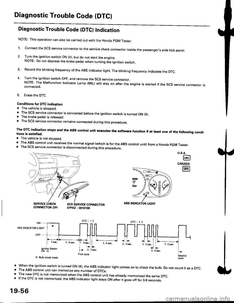
Diagnostic Trouble Code {DTC) Indication
NOTE: This operation can also be carried out with the Honda pGM Tesrer.
l connect the scs service connector to the service check connector inside the passenger,s side kick panel.
2. Turn the ignition switch ON (||). but do not start the engine.NOTE: Do not depress the brake pedal when turning the ignition switch.
3 Record the brinking frequency of the ABS indicator right. The brinking frequency indicates the DTc.
4, Turn the ignition switch OFF, and remove the SCS service connector.NorE: The Mslfunction Indicator Lamp (MlL) will stay on after the engine is started if the scs service connector isconnected.
5. Erase the DTC.
Condhions for DTC indication. The vehicle is stoDDed.. The SCS service connector is connected before the ignition switch is turned ON fll).. The brake pedal is released.. Th€ SCS service connector remains connected during this procedure
The DTG indication stops 8nd the ABs conltol unit executes the softwaro tunqtion if at least one of the following condi-tions b satisfied:
o The vehicle is not stoDoed.' The ABS control unit receives the normat signal (which is for the ABS controt unit) from a Honda pGM Tester.. The SCS service connector is disconnected during this procedu.e,
u.s.A.
@
CANADA
@
SERVICE CHECKCONNECTOR {2PISCS SERVICE CONNECTOR07PAZ - 0010100
ABS INDICATOR LIGHT
DTC : 3 3
A8S INDICAIOR LIGHT
Snilion swirch
' when the ignition switch is turned oN (ll), the ABs indicator light comes on to check the bulb. Do not count it as a DTc.o The ABS control unit can memorize any number of DTCs.. The new DTC is not memorized when the ABS control unit has already memorized the same DTC,.lftheDTCisnotmemorized,theABSindicatorlightstaysONafteritgoesofffor3.6seconds.
19-56
Page 1228 of 2189
\il
Modulator Unit
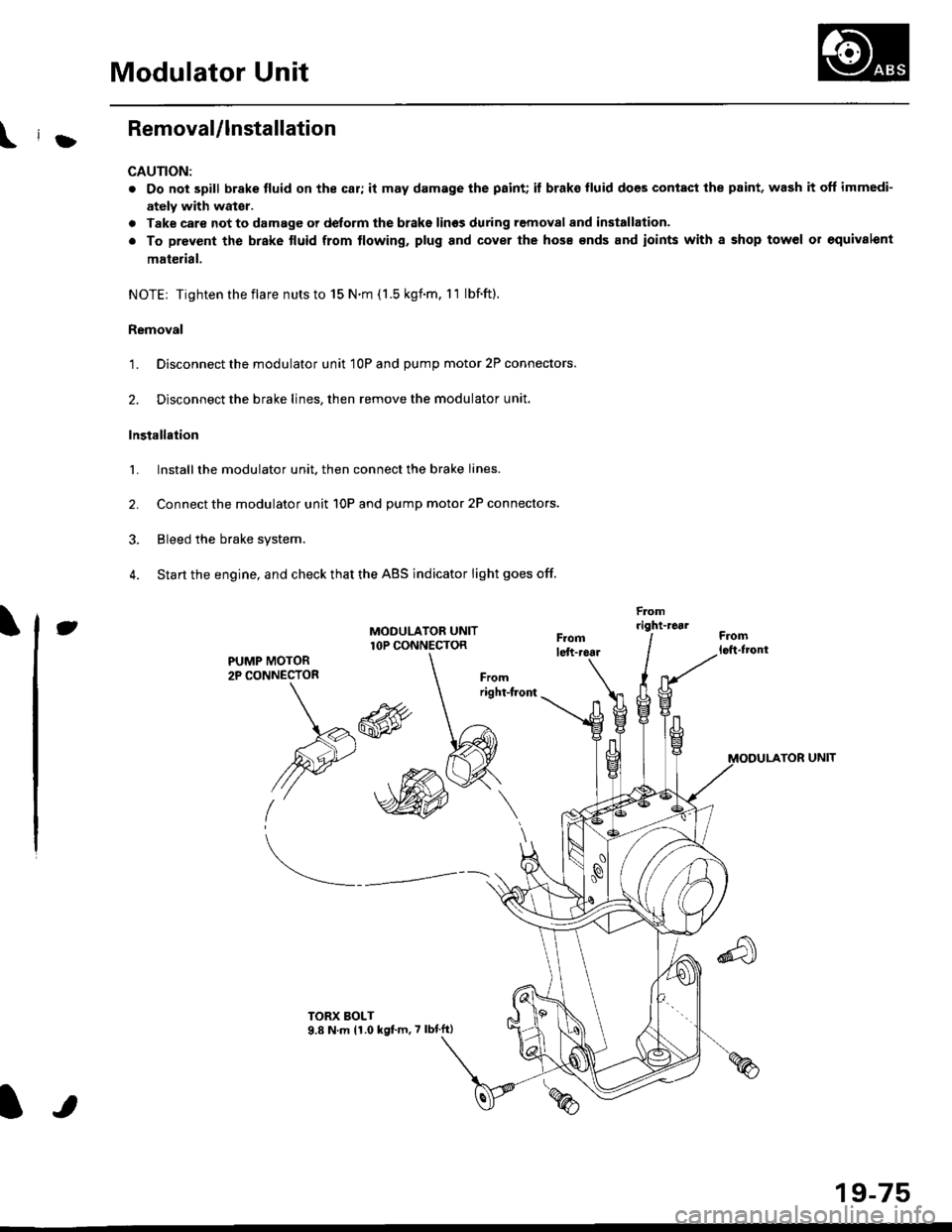
RemovaUlnstallation
CAUTION:
. Do not spill brake tluid on the car; it may damage the paint; it brako lluid does contact the paint, wash it off immedi-
ately with wator.
a Take care not to damage or delorm the brake lin€s during removal and installation.
. To prevent the brake tluid from tlowing, plug and cover the hose €nds and ioints with a shop tow6l or equivalent
mat€rial.
NOTE| Tightentheflare nutsto 15 N.m (1.5 kgnm. l1 lbf.ft).
Removal
'1. Disconnect the modulator unit 10P and Dump motor 2P connectors.
2. Disconnect the brake lines, then remove the modulator unit.
Installaiion
1. Install the modulator unit. then connect the brake lines.
2. Connect the modulator unit 10P and oumD motor 2P connectors.
3. Bleed the brake system.
4. Start the engine, and check that the ABS indicator light goes off.
Fomright-1461
PUMP MOTOR2P CONNECTOR
J
-R
/2e'
t'
TOR UNIT
tt
19-75
Page 1260 of 2189
Windshield
Installation (cont'd)
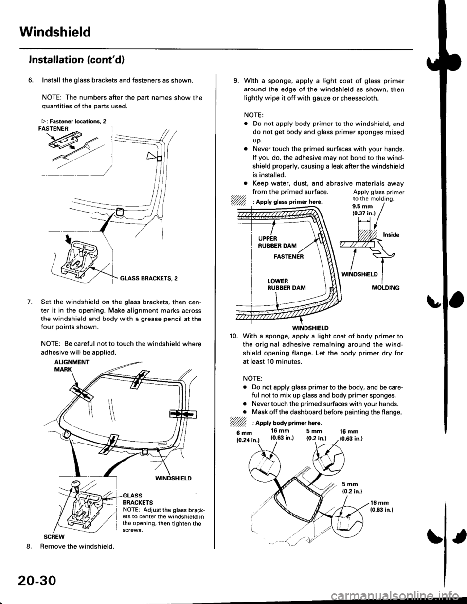
Installthe glass brackets and fasteners as shown.
NOTE: The numbers after the part names show thequantities of the oarts used.
GLASS BRACKETS, 2
Set the windshield on the glass brackets, then cen-
ter it in the opening. Make alignment marks across
the windshield and body with a grease pencil at the
four points shown.
NOTE: Be careful not to touch the windshield where
adhesive will be aDolied.
7.
8. Remove the windshield.
20-30
>: Fastoner locations, 2FASTENER ^ I
I
SCREW
9. With a sponge, apply a light coat of glass primer
around the edge of the windshield as shown. then
lightly wipe it off with gauze or cheesecloth.
NOTE:
. Do not apply body primer to the windshield. and
do not get body and glass primer sponges mixed
up.
. Never touch the primed surfaces with your hands.
lf you do. the adhesive may not bond to the wind-
shield properly, causing a leak after the windshield
is installed.
. Keep water. dust, and abrasrve
from the primed surface.t/////,'/////l I Apply glass p.imer here.
materaals away
Apply glass primerto the molding.
WINDSHIELD
10. With a sponge. apply a light coat of body primer to
the original adhesive remaining around the wind-
shield opening flange. Let the body primer dry for
at least 10 minutes.
NOTE:
. Do not apply glass primer to the body, and be care-
ful not to mix up glass and body primer sponges.
. Never touch the primed surfaces with your hands.
. Mask off the dashboard before painting the flange.7////l/////l I Apply body p mer hcre.
6mm16mm 5mm(0.6:| in.) (0.2 in.l16 mm
{0,63 in.}
/
MOLDING
Page 1264 of 2189
Rear Window
Installation (cont'dl
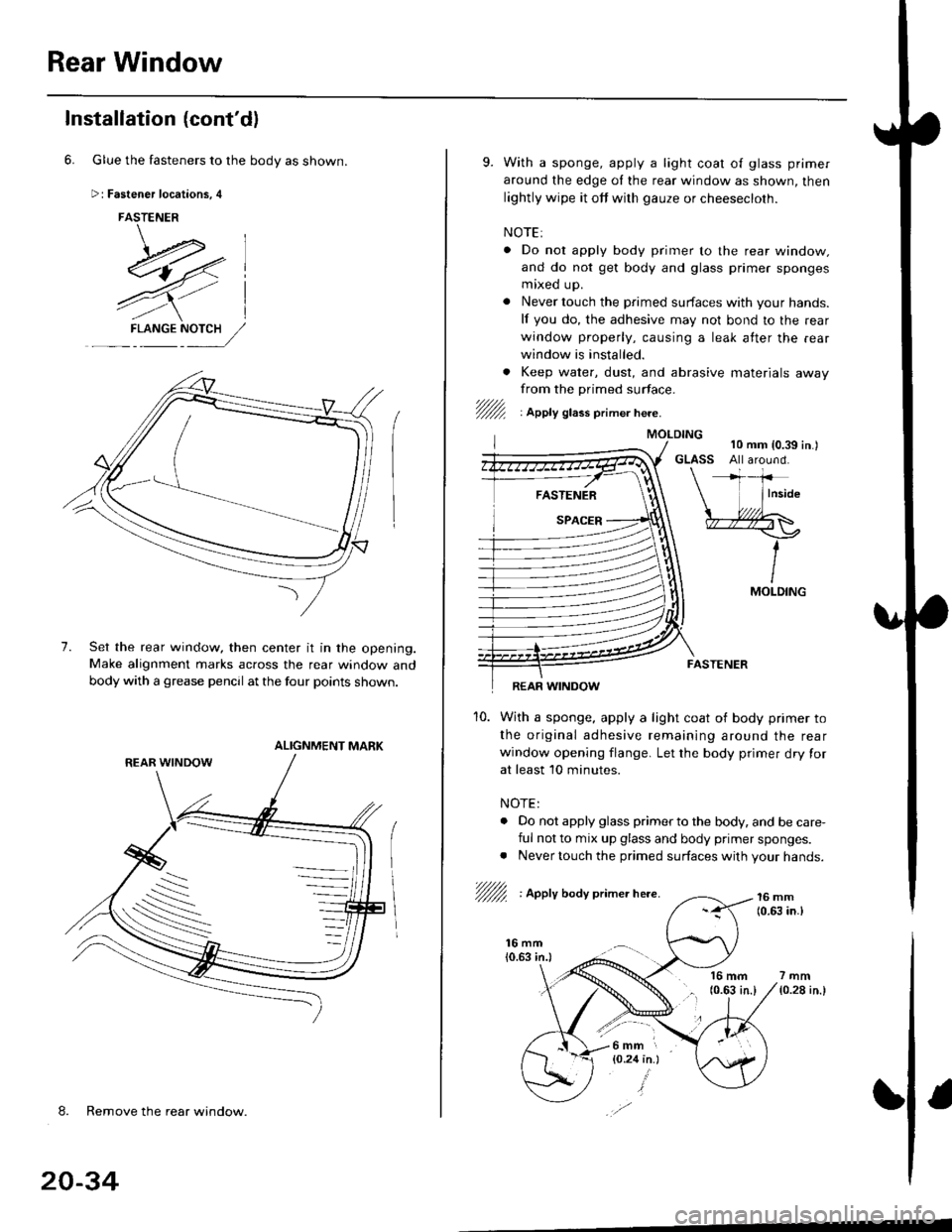
6. Glue the fasteners to the body as shown.
Fastener locations, 4
FASTENER
\-.*l-E4,7-- ,.--
7),/l
4Yl
7.
F-L NGENY:,//
Set the rear window, then center it in the opening.Make alignment marks across the rear window and
body with a grease pencll at the four points shown.
ALIGNMENT MARK
-\
-.._s
-
8. Remove the rear window.
20-34
9. With a sponge, apply a light coat o{ glass primer
around the edge oI the rear window as shown, then
lightly wipe it off with gauze or cheesecloth.
NOTE:
. Do nol apply body primer to the rear window.
and do not get body and glass primer sponges
mixed up.
. Never touch the primed surfaces with your hands.
lf you do, the adhesive may not bond to the rear
window properly, causing a leak atter the .ear
window is installed.
. Keep water, dust, and abrasive materials awayfrom the primed surface.'/fur1 : lppty gtass primer here.
16 mm(0.63 in.l7mm
{0.28 in.}
FASTENER
REAR WINDOW
10. With a sponge, apply a light coat of body primer to
the original adhesive remaining around the rear
window opening flange. Let the body primer dry for
at least 10 minutes.
NOTE:
. Do not apply glass primer to the body. and be care,
ful not to mix up glass and body primer sponges.. Never touch the primed surfaces with your hands.
/fu/ : Apply boay primer here.16 mm(0.(I, in.l
MOI-DING
l6mm r
{O.24 in.}
Page 1268 of 2189
Rear Window
Installation (cont'd)
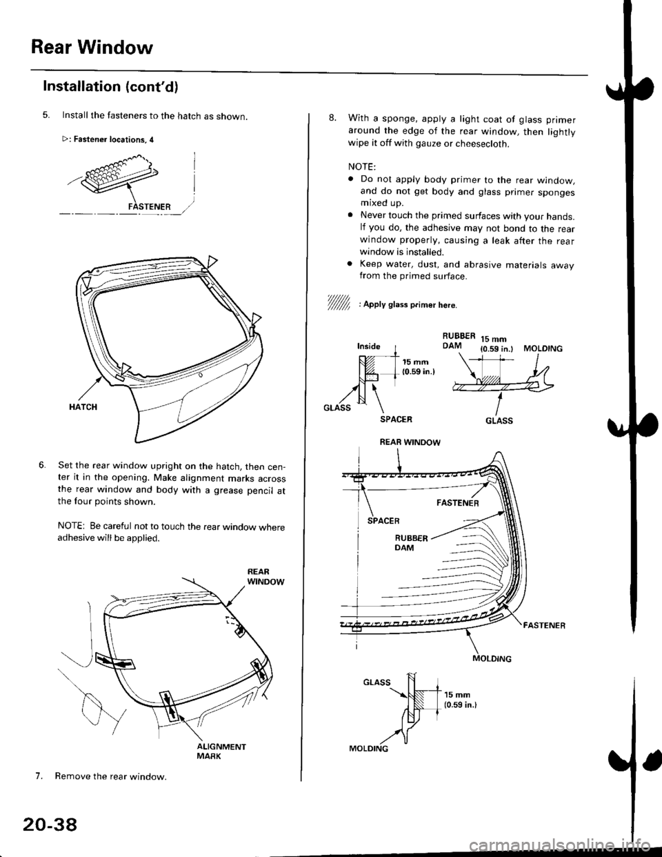
Install the fasteners to the hatch as snown.
>: Fastener locations, 4
Set the rear window upright on the hatch, then cen-ter it in the opening. Make alignment marks acrossthe rear window and body with a grease pencil atthe four points shown.
NOTE: Be careful not to touch the rear window whereadhesive will be applied.
7. Remove the rear window.
20-38
8. With a sponge. apply a light coat of glass primer
around the edge of the rear window, then lightlywipe it off with gauze or cheesecloth.
NOTE:
. Do nol apply body primer to the rear window,and do not get body and glass primer spongesmaxed up.
. Never touch the primed surfaces with your hands.lf you do, the adhesive may not bond to the rearwindow properly, causing a leak after the rearwindow is installed.
. Keep water, dust, and abrasive materials awayfrom the primed surface.
RUBBERDAM15 mm{0.59 in.l MOLDING
V/////f , apety st,." o.imer here.
Inside I---- - -t-
tUt I 15mm| @- L 10.59 in.lNJ-l trll \
,zN \GLASS \SPACER
FASTENER
GLASS
REAR WINOOW
Page 1273 of 2189
t
l
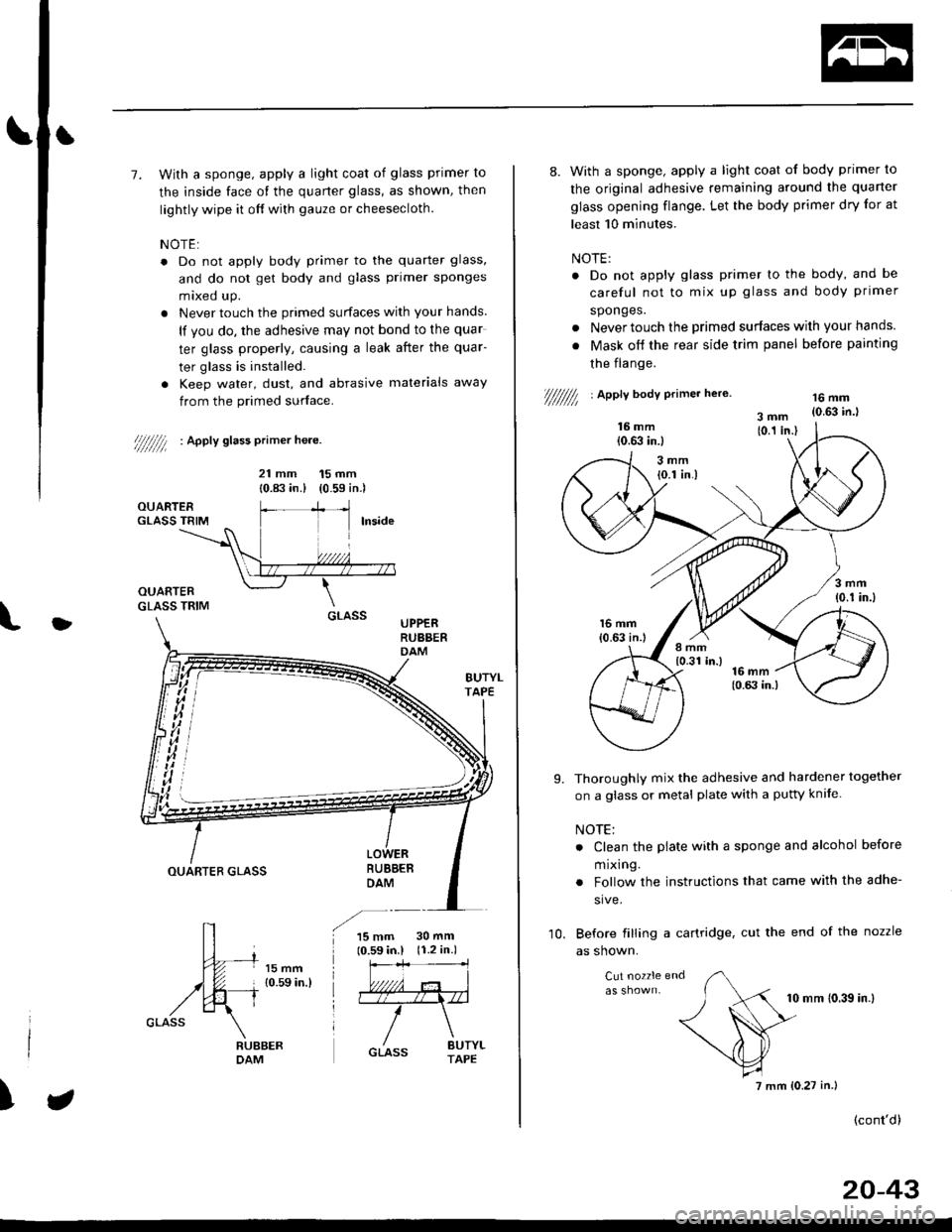
7. With a sponge, apply a light coat of glass primer to
the inside face of the quarter glass, as shown, then
lightly wipe it off with gauze or cheesecloth.
NOTE:
. Do not apply body primer to the quarter glass,
and do not get body and glass primer sponges
mixed up.
. Never touch the primed surfaces with your hands.
lf you do, the adhesive may not bond to the quar
ter glass properly, causing a leak after the quar-
ter glass is installed.
. Keep water, dust, and abrasive materials away
from the primed surface.
////////l : ^pptv stass primer he.e.
21 mm 15 mm
{0.83 in.) (0.59 in.)
UPPERRUBBERDAM
BUBBEBDAMOUARTER GLASS
15 mm10.59 in.l30 mm(r.2 in.)
)
8. With a sponge, apply a light coat of body primer to
the original adhesive remaining around the quarter
glass opening flange. Let the body primer dry for at
least 10 minutes.
NOTE:
. Do not apply glass primer lo the body, and be
careful not to mix up glass and body primer
sponges.
. Never touch the primed surfaces wilh your hands.
. Mask off the rear side trim panel before painting
the flange.
///////// | apetl body erimer he,e.16 mm{0.63 in.l
Thoroughly mix the adhesive and hardener together
on a glass or metal plate with a pufty knife.
NOTE:
. Clean the plate with a sponge and alcohol before
m rxlng.
. Follow the instructions that came with the adhe-
sive.
Before filling a cartridge, cut the end of the nozzle
as shown.
Cut nozzle end
10 mm (0.39 in.l
(cont'd)
9.
10.
7 mm (0.27 in.)
20-43