mat HONDA CIVIC 1999 6.G Workshop Manual
[x] Cancel search | Manufacturer: HONDA, Model Year: 1999, Model line: CIVIC, Model: HONDA CIVIC 1999 6.GPages: 2189, PDF Size: 69.39 MB
Page 1314 of 2189
Rear Seat
Seat Cover Replacement (cont'dl
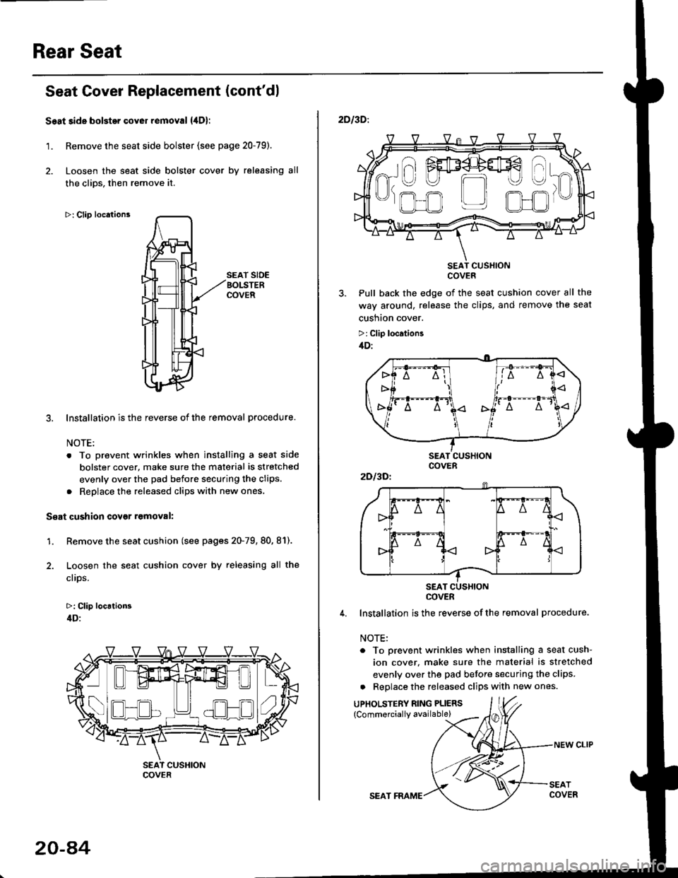
Seat side bolstor cover removal {,lDl
1. Remove the seat side bolster (see page 20-79).
2. Loosen the seat side bolster cover by releasing all
the clios, then remove it.
>: Clip locations
SEAT SIDEBOLSTERCOVER
3. Installation is the reverse of the removal procedure.
NOTE:
. To prevent wrinkles when installing a seat side
bolster cover, make sure the material is stretched
evenly over the pad before securing the clips.
. Reolace the released cliDs with new ones,
S€at cushion covgr r6moval:
1. Remove the seat cushion (see pages 20-79, 80, 81).
2. Loosen the seat cushion cover by releasing all the
clips.
>: Clip locrtion3
4D:
- -I ./al--lt___)l ) ( .)Ll!!l^t!!l 1",
COVER
20-a4
SEAT FRAME
NEW CLIP
2DI3D:.
SEAT CUSXIONCOVER
Pull back the edge of the seat cushion cover all the
way around, release the clips, and remove the seat
cusnton cover.
>: Clip location3
/tD:
4. Installation is the reverse ofthe removal procedure.
NOTE:
. To prevent wrinkles when installing a seat cush-
ion cover. make sure the material is stretched
evenly over the pad before securing the clips.
a Replace the released clips with new ones.
UPHOLSTERY RING PLIERS
{Commerciallv available)
a\
------)
t" I FEF4+#€
R-U U m
'J)
,.ofl r_r olJr
2Dl3Dl
COVER
Page 1321 of 2189
Seat Belts
Inspection
t.
Retractor InsDection
Before installing the retractor, check that the seat belt
can be pulled out freely.
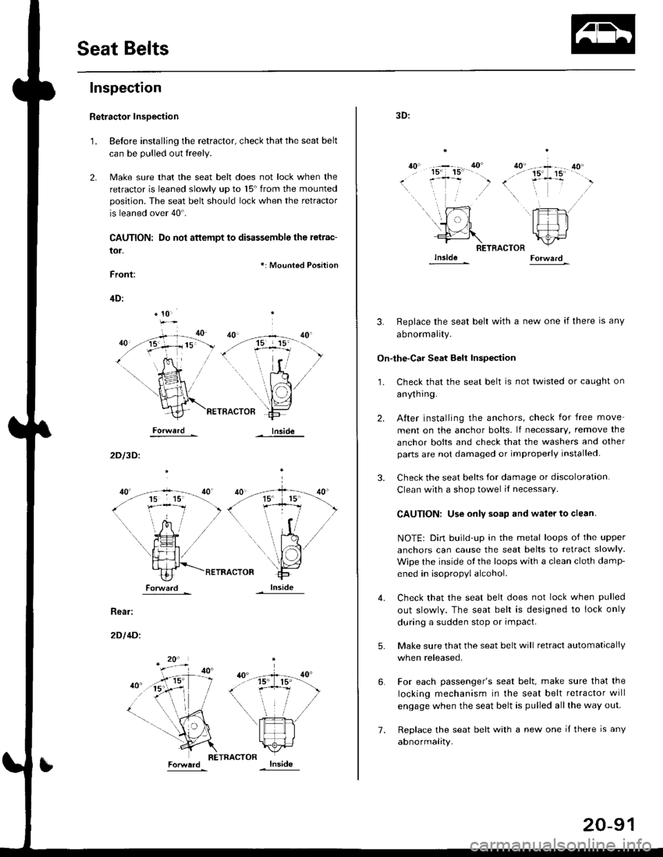
Make sure that the seat belt does not lock when the
retractor is leaned slowly up to 15'from the mounted
position. The seat belt should lock when the retractor
is leaned over 40'.
CAUTION: Do not attempt to disassemble the retrac-
tor.
Front:
*: Mounted Position
Inside
4D:
Forward
2D l3D.
Rear:
2D l4Di
* 10-
15 15'
i-Tl
I ],f
ForwaJdlnside
7.
20-91
3D:
ao"40'- -+ 40...'' 15' 15' --
(. .-j- ,)\,
RETRACTOR
3. Replace the seat belt with a new one if there is any
abnormality.
On-lhe-Car Seat Belt Inspeqtion
2.
3.
1.
5.
6.
4.
Check that the seat belt is not twisted or caught on
anyrn I ng.
After installing the anchors, check for free move
ment on the anchor bolts. lf necessary, remove the
anchor bolts and check that the washers and other
parts are not damaged or improperly installed
Check the seat belts for damage or discoloration.
Clean with a shop towel il necessary
CAUTION: Use only soap and water to clean.
NOTE: Dirt build-up in the metal loops of the upper
anchors can cause the seat belts to retract slowly.
Wipe the inside ot the loops with a clean cloth damF
ened in isopropyl alcohol.
Check that the seat belt does not lock when pulled
out slowly. The seat belt is designed to lock only
during a sudden stop or impact.
Make sure that the seat belt will retract automatically
when released.
For each passenger's seat belt, make sure that the
locking mechanism in the seat belt retractor will
engage when the seat belt is pulled all the way out.
Replace the seat belt with a new one il there is any
abnormality.
Page 1334 of 2189
Door and Side Moldings
Replacement (cont'dl
Door molding removal:
The following materials and tools are required to repairthe door moldings.
NOTE: Followthe manufacturer's instructions.
Materials: (Reference)
. Stripe remover
3M 08907
Stripe adhesive remover
3M 08908
Adhesive tape
3M Super Automotive Attachment Tape
Tools;
a Protective tape
. Knife or Cutter
. Sponge or Shop towel. Infrared dryer
. Film
. Putty knife
. Alcohol
CAUTION: Put on gloves to protect your hands,
Remove the door panel, and pull back the plastic
cover,
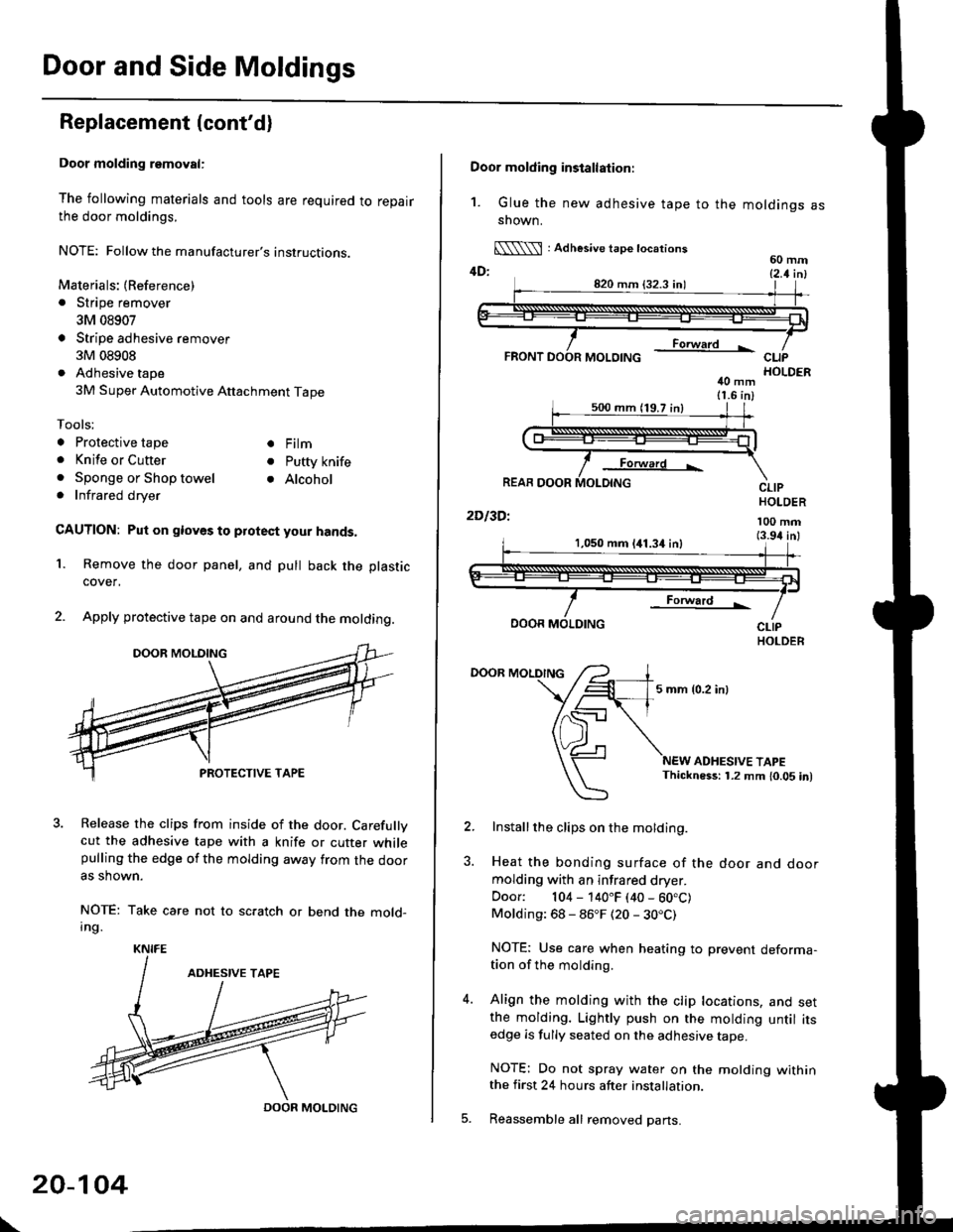
Apply protective tape on and around the molding.
3. Release the clips from inside of the door. Carefullvcut the adhesive tape with a knife or cutter whilepulling the edge of the molding away trom the dooras shown.
NOTE: Take care not to scratch or bend the mold-Ing.
1.
KNIFE
DOOR MOLDING
\
20-104
Door molding installation:
1. Glue the new adhesive tape to the moldings assnown.
[\\\l : Adhesive tape tocations60 mm4D: t2 t i^l
40 mm11.6 in)
Forward L
REAR DOOR
2Dl3Dl
CLIPHOLDER
100 mm(3.94 inl1,050 mm 141.34 inl
Forward !
DOOR MOLDING
DOOR MOLDING
5 mm {0.2 inl
ADHESIVE TAPEThickness: 1.2 mm 10.05 in)
Installthe clips on the molding.
Heat the bonding surface of the door and doormolding with an infrared dryer.
Door: 104 - 140"F (40 - 60.C)Molding: 68 - 86"F (20 - 30.C)
NOTE: Use care when heating to prevent deforma-tion of the molding.
Align the molding with the clip locations, and setthe molding. Lightly push on the molding until itsedge is fully seated on the adhesive tape.
NOTE: Do not spray water on the motding withinthe first 24 hours after installation.
Reassemble all removed pans.
Page 1338 of 2189
Opener Cables
Replacement
NOTE:
t When removing the clips. use a clip remover.. Take care not to bend the opener cables.
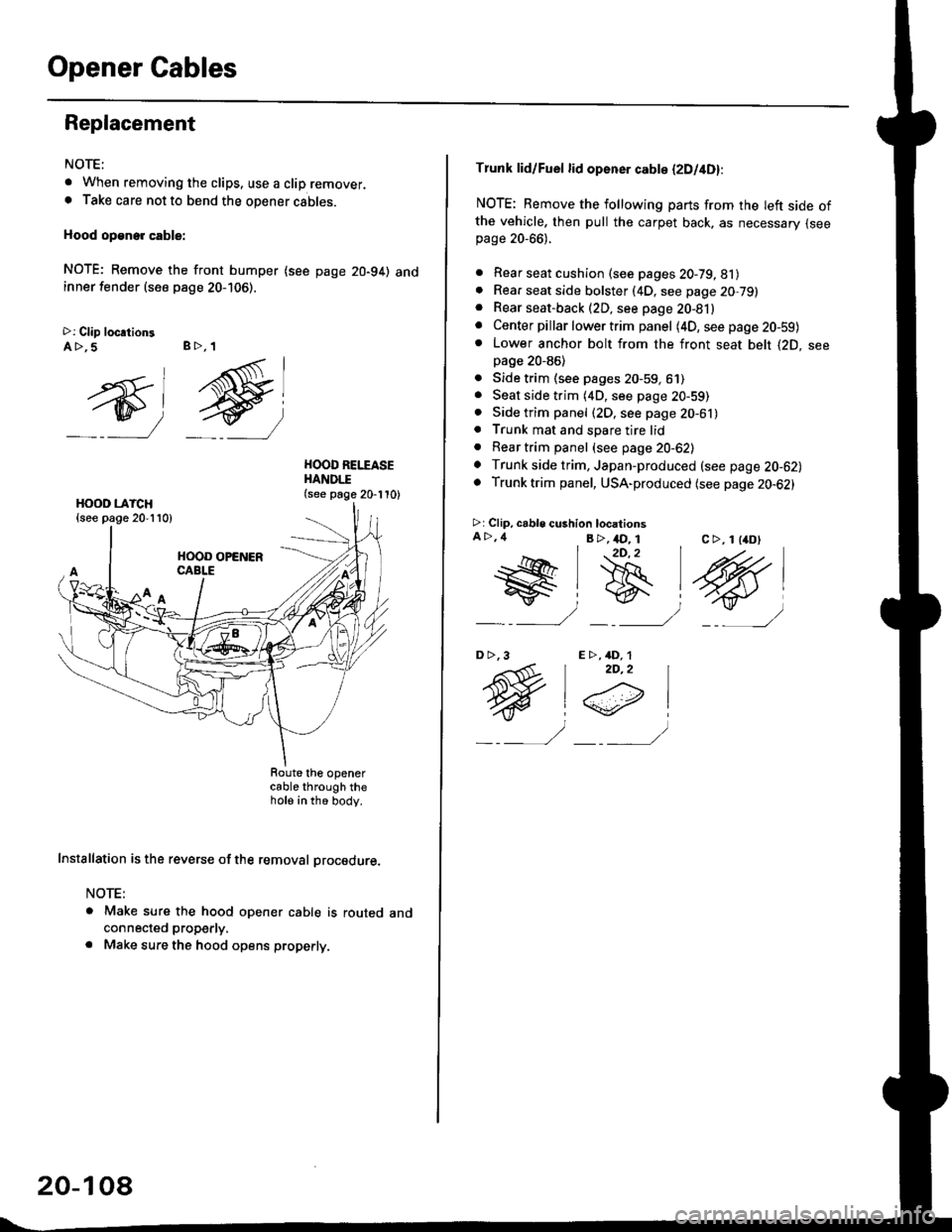
Hood op€ne. cable:
NOTE; Remove the front bumper (see page 20-94) andinner fender (see page 20-106).
>: Clip loc.tionsA >,5 B>, 1
ry)
g
HOOD REI.TASEHANDI.I(see page 20-110)
cable through thehote in th6 body.
Installation is the reverse of the removal procedure.
NOTE:
a Make sure the hood opener cable is routed andconnected properly.
. Make sure the hood opens properly.
20-10a
Tlunk lid/Fuel lid opener cabte (2Dl4D):
NOTE: Remove the following parts from rhe Ieft side ofthe vehicle, then pull the carpet back, as necessary {seepage 20-66).
. Rear seat cushion (see pages 20-79, 81). Rear seat side bolster (4D, see page 20,79). Rear seat-back (2D, see page 20-81). Center pillar lower trim panel (4D, seepage20-59)o Lower anchor bolt from the front seat belt {2D. seepage 20-86)
. Side trim (see pages 20-59, 61). Seat side trim (4D, see page 20-59). Side trim panel (2D, see page 20-61). Trunk mat and spare tire lid. Reartrim panel (see page 20-62). Trunk side trim, Japan-produced (see page 20-62). Trunk trim panel, USA-produced (see page 20-62)
>r Clip, cable cushion locationsA >,4 B >,4D_ 1c >, 1 l4D)2D,2
t@#lB
_ : _/ _-___)
E >,4D, 12D,2
@i
_ _,, -/
D>,3
Page 1347 of 2189
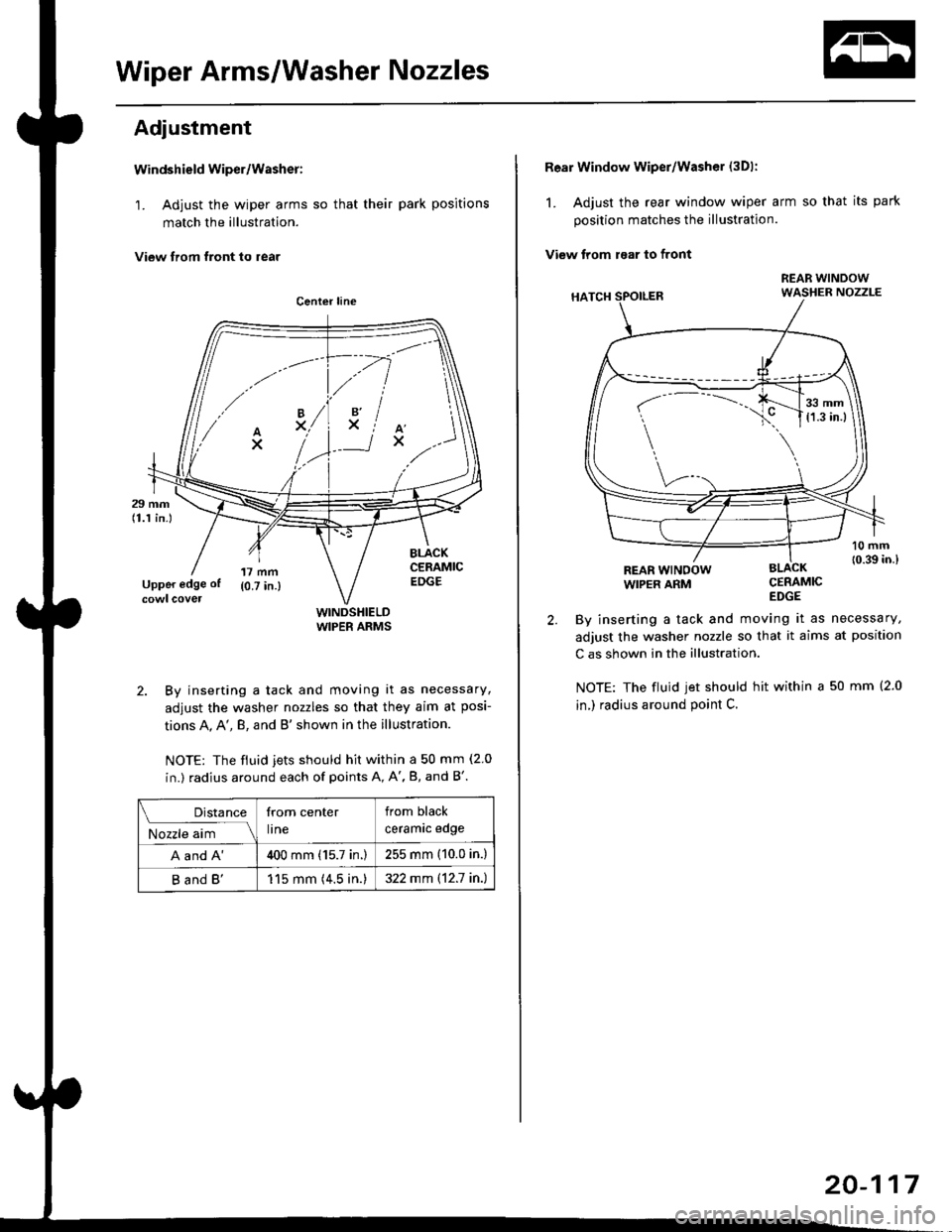
Wiper Arms/Washer Nozzles
Adjustment
Windshield wiper/Washer:
1. Adjust the wiper arms so that their park positions
match the illustration.
View trom tront to rear
WINDSHIELDWIPER ARMS
2. By inserting a tack and moving it as necessary,
adjust the washer nozzles so that they aim at posi-
tions A, A', B, and B'shown in the illustration.
NOTE: The fiuid jets should hit within a 50 mm (2 0
in.) radius around each of points A, A', B, and B'.
.// \
A'x..
-.4
,'lxiAx
Distance
M;r.";-lll
from center
lrne
from black
ceramrc eoge
A and A'400 mm (15.7 in.)255 mm (10.0 in.)
B and B'115 mm (4.5 in.)322 mm \12.7 in.)
Rear Window wiper/Washer (3Dl:
1. Adjust the rear window wiper arm so that its park
position matches the illustration.
View trom raar to front
CERAMICEDGE
By inserting a tack and moving it as necessary,
adjust the washer nozzle so that it aims at position
C as shown in the illustration.
NOTE: The fluid jet should hit within a 50 mm (2.0
in,) radius around point C.
REAR WINOOWWIPER ARM
r-
---..J_.__11,:l
20-117
Page 1356 of 2189
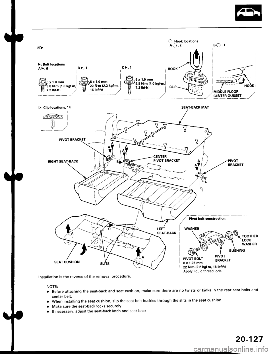
,-. ): Hook locations^(:).zB() ' t2D:
>: Bolt locationsA>,6c>,1B>. 1
6le
9rJ*'Ll-",-, i VH 16 rbr'frl ) g
,/v
6x1.omm i9.8 N.m 11.0 ksf.m,l7.2 rbf.ft) i
>: Clio locations, 14
PIVOT BRACKET
V
CENTER
RIGHT SEAT-BACK
LEFTSEAT-BACK
SEAT CUSHION
lnstallation is the reverse of the removal procedure.
NOTE:
. Before attaching the seat-back and seat cushion, make sure there are
center belt.
. When installing the seat cushion, slip the seat belt buckles through the
. Make sure the seat-back locks securely
. lf necessary, adjust the seat-back latch and seat-back
BUSHING
PIVOT BOLTBRACKET8 x 1.25 mm22 N.m {2.2 kgf.m, 16 lbIft)Apply liquid thread lock.
no twists or kinks in the rear seat belts and
slits in the seat cushion.
SEAT-AACK MAT
VV
TOOIHEDLOCKWASHER
PIVOT BRACKET
20-127
Page 1368 of 2189
Reassemble in the reverse order of disassembly' and
note these items:
. Make sure the bushing and pivot washer are installed
properly.
. To connect the connecting wire, twist it 90'.
. Replace the back cover clips with new ones
. To prevent wrinkles when installing the seat-back
cover, make sure the material is stretched evenly
over the pad.
. Apply multipurpose grease to the moving portion of
the seat track.
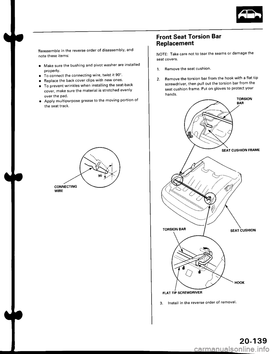
Front Seat Torsion Bar
Replacement
NOTE| Take care not to tear the seams or damage the
seat covers.
1. Remove the seat cushlon
2. Remove the torsion bar from the hook with a flat tip
screwdriver, then pull out the torsion bar from the
seat cushion frame Put on gloves to protect your
ha nds.
TORSIONSAR
SEAT CUSHION FNAME
TORSION BARSEAT CUSHION
FLAT TIP SCREWDRIVER
3. lnstall in the reverse order of removal'
20-139
Page 1374 of 2189
Heater and Air Conditioning
Heater '.'..""" 21'1
Air Conditioning ......."'.. "' 22-1
SUPPLEMENTAL RESTRAINT SYSTEM (SRS}
The civic sRs includes a driver's airbag located in the steering wheel hub ln addition, all models (except some
models for canada) have a passenger's airbag located in the dashboard above the glove box'
Information necessary to safely service the sRS is included in this service Manual ltems marked with an asterisk (*)
on the contents page include, or are located near, sRs components. servicing, disassembling or replacing these
items will require special precautions and tools, and should therefore be done by an authorized Honda dealer'
@-";;il rendsring the SRS inoperative, which could lead to personal iniury or deaih in the svent of a sev€re
frontal collision. all SRS service work must be pertormed by an authorized Honda d€aler'
. lmploper service procedures, including incorrest removal and instsllation of the sRs, could lead to personal
iniury caused by unintentional deployment of the airbags'
o Do not bump the SRS unit. Otherwise. the system may fait in case of a collision. or the airbags may deploy
when the ignition switch is ON {ll}'
. sRs electrical wiring harncsses are id€ntified by yellow colol coding. Related components ale located in lhe
steering column, front console, dashboard, dashboald lowet panel, and in the dashboard above the glove box'
Do not use electricaltest equipment on these circuits.
Page 1420 of 2189
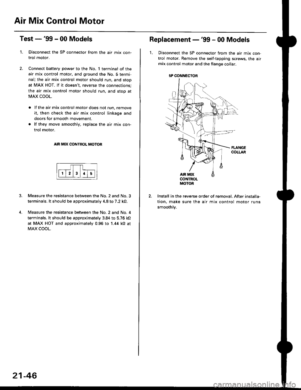
Air Mix Gontrol Motor
't.
Test -'99 - 00 Models
Disconnect the 5P connector from the air mix con-
trol motor.
Connect battery power to the No. 1 terminal of the
air mix control motor, and ground the No. 5 termi,
nal; the air mix control motor should run, and stop
at MAX HOT. lf it doesn't, reverse the connections;
the air mix control motor should run, and stop at
MAX COOL.
lf the air mix control motor does not run, remove
it, then check the air mix control linkage and
doors for smooth movement.
lf they move smoothly, replace the air mix con-
trol motor.
AIR MIX CONTROL MOTOR
Measure the resistance between the No.2 and No.3
terminals. lt should be approximately 4.8 to 7.2 kO.
Measure the resistance between the No. 2 and No. 4
terminals. lt should be approximately 3.84 to 5.76 kO
at MAX HOT and approximately 0.96 to 1.44 kO at
MAX COOL.
21-46
5P OONNECYOB
Replacement -'99 - 00 Models
1, Disconnect the 5P connector from the air mix con-
trol motor. Remove the self-tapping screws, the airmix control motor and the flange collar.
CONTROLMOTOR
Install in the reverse order of removal. After installa-
tion, make sure the air mix control motor runs
smoothly.
Page 1446 of 2189
A/C Service Tips and Precautions
The air conditioner system uses HFC-134a (R-134a) refrigerant and polyalkyleneglycol (PAG) refrigerant oil*, which are not
compatible with CFC-12 (R-12) refrigerant and mineral oil. Do not use R-12 refrigerant or mineral oil in this system, and do
not attempt to use R-12 servicing equipmenU damage to the air conditioner system or your servicing equipment will result.*Sanden SP-10:
. P/N 38897 - P13 - A0lAH: 120 ml 14ll.oz, 4.2lmp.oz)
. P/N 38899 - P13 - A0l | 40 mf 11 1/3ll.oz,1.4 lmp'oz)
Use only service equipment that is U.L. listed and is certified to meet the requirements of SAE J2210 to remove R 134a
from the air conditioner system.
CAUTION: Exposure to air conditioner ref;ige;ant and lubricant vapol or mist can irritate syes, nose and throat, Avoid
breathing the air conditioner refrigerant and lubricant vapor or misl.
lf accidental system discharge occurs, ventilate work area before resuming service.
R-'134a service equipment or vehicle air conditioner systems should not be pressure tested or leak tested with compressed
ai.
!@@ some mixtures of air and R-t3ila have been shown to be combustible at elevated pressures and can result
in tire or explosion causing iniury or property damage. Never use compressed air lo pressure tesl R-134a service equip-
ment or vehicle 8ir conditioner systoms.
Additional health and safety information may be obtained from the refrigerant and Iubricant manufacturers.
L Always disconnect the negative cable from the battery whenever replacing air conditioning pans.
2. Keep moisture and dust out of the system. When disconnecting any lines, plug or cap the fittings immediately; don't
remove the caps or plugs until just before you reconnect each line.
3. Before connecting any hose or line, apply a few drops of refrigerant oilto the O-ring.
4, When tightening o. loosening a fitting, use a second wrench to support the matching fitting.
5. When discharging the system, use a R-134a refrigerant recovery/recycling/charging station; don't release refrigerant
into the atmosphere,
6. Add refrigerant oil after replacing the following parts:
NOTE:
. To avoid contamination, do not return the oil to the container once dispensed, and never mix it with other refriger-
ant oils.
. lmmediately after using the oil, replace the cap on the container, and seal it to avoid moisture absorption.
. Do not spill the refrigerant oil on the vehicle; it may damage the paint; if the refrigerant oil contacts the paint, wash
it off immediately.
Condenser .......2o ml (2/3 fl.oz, 0.7 lmp.ozl
Evaporator .,.,.,. i[5 m{ 11 213 tl.oz,1,6lmp.ozl
Line or hose ..... 10 mf (1/3 fl.oz, 0.4 lmp.ozl
Receiver/Dryer 10 m{ (1/3 fl.oz,0.'l lmp.ozl
Leakage repair 25 m{ (5/6 fl.oz, 0.9 lmp.ozl
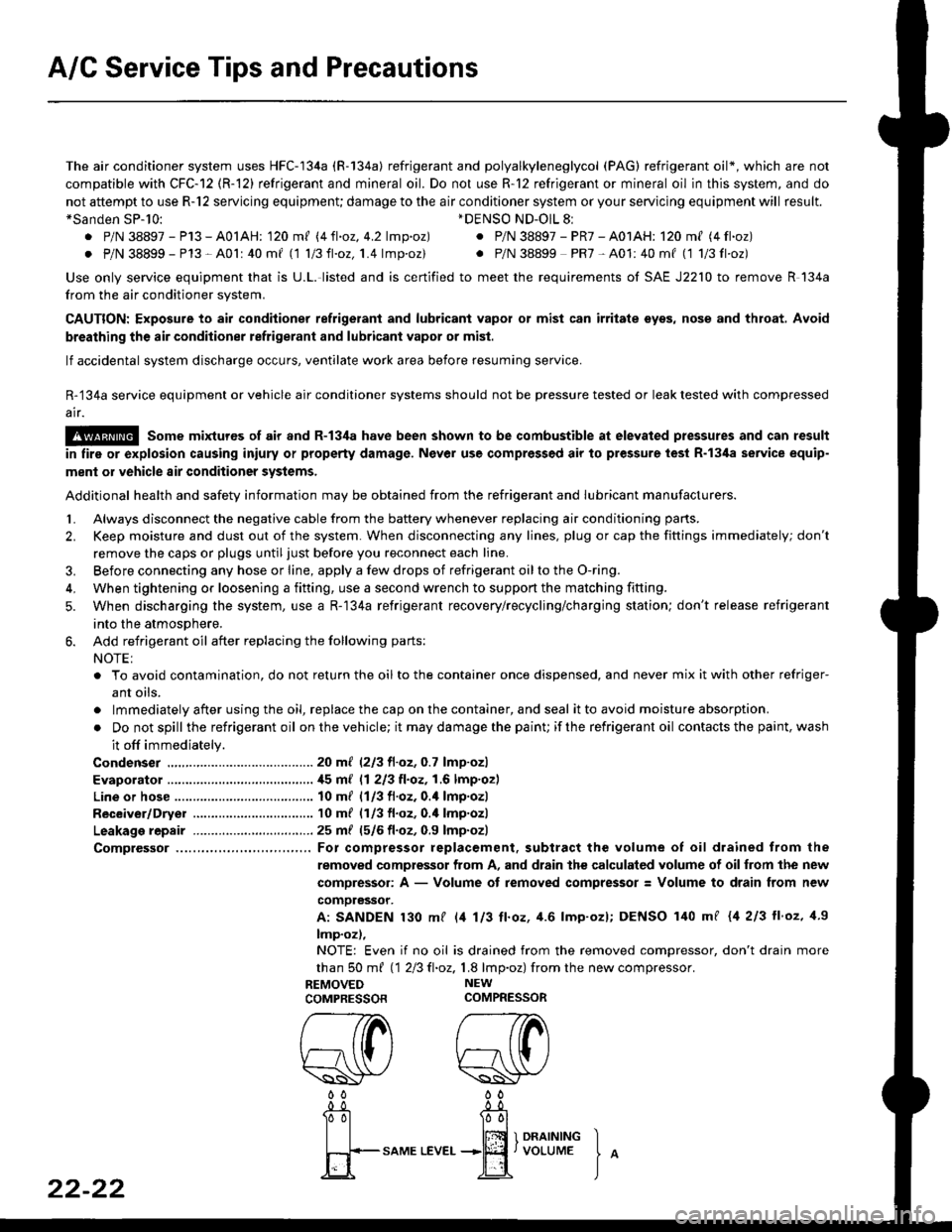
Comptessor ... For compressor replacement. subtract the volume of oil drained trom the
removed compressor from A, and drain the calculated volume of oilfrom the new
compressor: A - Volume of removed compressor: Volume to drain from new
comoressor.
A: SANDEN 130 mf l/t 113 ll.oz, 4.6 lmp'ozl; DENSO 140 mf {4 213 ll'oz, 1.9
lmp.oz),
NOTE: Even if no oil is drained from the removed compressor, don't drain more
than S0 m{ 112Ell.oz,1.8 lmp.oz) fromthe new compressor.
REMOVED NEW
COMPRESSORCOMPRESSOR
*DENSO ND-OlL 8l
. P/N 38897 - PR7 - A01AH: 120 ml (4 fl.oz)
. P/N 38899 PR7-A01:40mf (1 1/3fl'oz)
rereW W0000
22-22
-0_!- -0_a
Tol l00l
| | lffi 1 onrrrutrc I
fi+-sAME
LEvEr...+jEf,voLUME
J
^