mat HONDA CIVIC 1999 6.G Workshop Manual
[x] Cancel search | Manufacturer: HONDA, Model Year: 1999, Model line: CIVIC, Model: HONDA CIVIC 1999 6.GPages: 2189, PDF Size: 69.39 MB
Page 1277 of 2189
t
\b
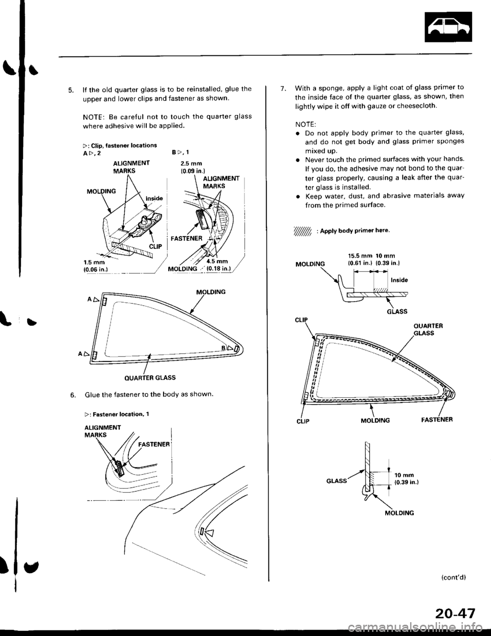
5. lf the old quarter glass is to be reinstalled, glue the
upper and lower clips and fastener as shown
NOTE: Be careful not to touch the quarter glass
where adhesive will be applied.
>: Clip, fastener locations
A>,2 B>, 1
2.5 mm(0.m in.)
Glue the fastener to the body as shown.
>: Fastener location, 1
6.
)
ALIGNMENT
7. With a sponge, apply a light coat of glass primer to
the inside face of the quaner glass, as shown, then
lightly wipe it off with gauze or cheesecloth
NOTE:
. Do not apply body primer to the quarter glass,
and do not get body and glass primer sponges
mixed up.
. Never touch the primed surfaces with your hands.
lf you do, the adhesive may not bond to the quar
ter glass properly, causing a leak after the quar-
ter glass is installed.
. Keep water, dust, and abrasive materials away
from the Primed surface
t///////7, , aootv a"av crimer here'
MOLDING
15.5 mm 10 mm10.61 in.l {0.39 in.l
(cont'dl
20-47
Page 1281 of 2189
Troubleshooting
SymptomProbable Cause
Water leaks1. Clogged drain tube.
2. Gap between glass weatherstrjp and roof panel.
3. Defective or improperly installed glass weatherstrip.
4. Gap between drain seal and roof panel.
Wind noise'1. Excessive clearance between glass weatherstrip and roof panel.
Motor noise1. Loose motor.
2. Worn gear or bearing.
3. Cable assembly deformed.
Glass does not move, but motor turns'1. Clutch out of adjustment.
2. Foreign matter stuck between guide rail and slider.
3. lnner cable loose.
4. Cable assembly not attached properly.
Glass does not move and motor does not turn
{glass can be moved with moonroof wrench)
1. Blown fuse,
2. Faulty switch.
3. Battery run down.
4. Defective motor.
5. Faulty relay.
D
Glass Height Adjustment
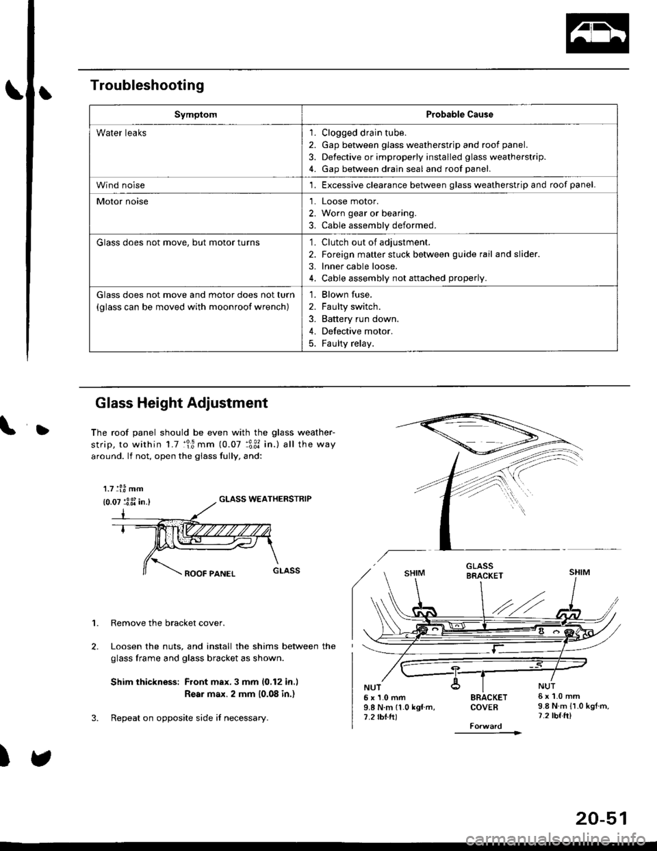
The roof panel should be even with the glass weather-
strip, to within 1.7 :lr3 mm (0.07 :3:31 in.) all the way
around. lf not, open the giass fully, and:
GLASS WEATHERSTRIP
1. Remove the bracket cover.
Loosen the nuts, and install the shims between the
glass frame and glass bracket as shown.
Shim thickness: Front max.3 mm 10,12 in.l
Rear max. 2 mm 10.08 in.)
Repeat on opposite side i{ necessary.
)
5x1.0mm9.8 N.m 11.0 kgf m,7.2 rbtft)
SRACKETCOVEB
----------1>
6x1.0mm9.8 N.m {1.0 kgtm,7.2 tbf.ft)
1.7 tl.8 mm
{0.07 :3 3i in.}
20-51
Page 1292 of 2189
Trunk Trim
Replacement
CAUTION:
. Put on gloves to proteci your hands.
. When prying with a flat-tip screwdriver, wrap it with protestive tap€ lo prevent damage.
NOTE:
. Take care not to bend or scratch the trim and panels.
. When removing the trunk side trim or trunk trim panel, fold the seat-back forward.
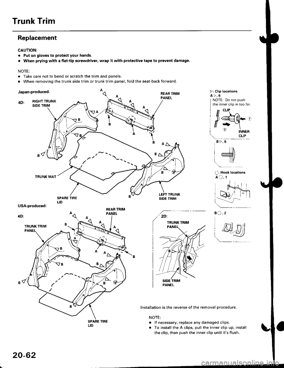
Japan-produced:
4D: RIGHT TRUNKSIDE TRIM
TRUNK MAT
1B
REAR TRIMPANEL
>: Clip locationsa>,6
a:-) ,2
I g cLlP ^
l#srq-'
| ' |NNER\- crLP
B >,6
NOTE: Do not push
the inner clip in too far.
IJ
LTro
i ) :Hook locations
A i--) , r
' 2D:
TRUNK TRIM
Installation is the reverse of the removal procedure.
NOTE:
. lf necessary. replace any damaged clips.
. To install the A clips. pull the inner clip up. install
the clip, then push the inner clip until it's flush.
(
,- --
/'/ \--
/ --
20-62
Page 1305 of 2189
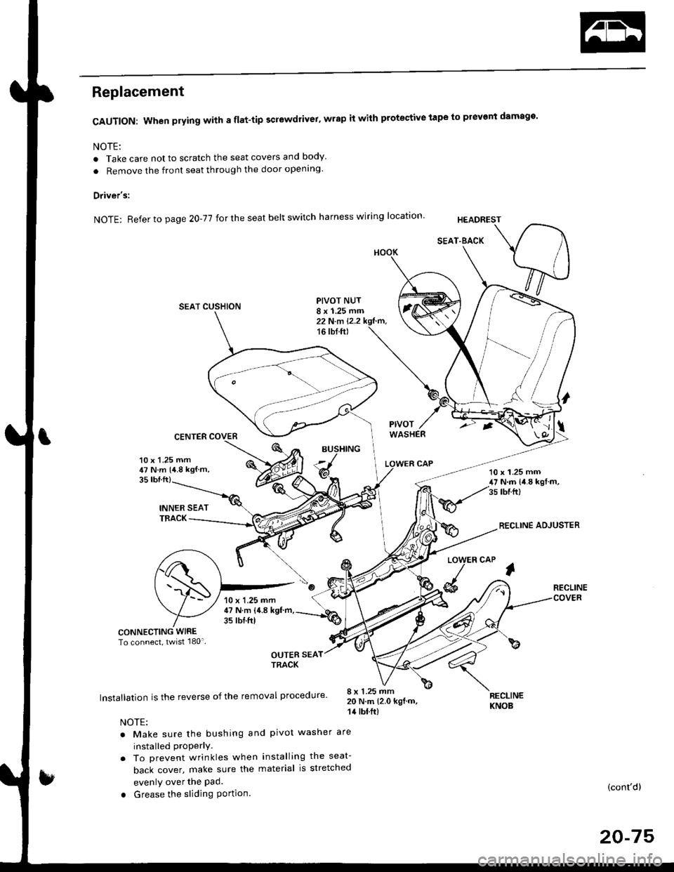
Replacement
CAUTION: When prying with a flat-tip screwdrivet, wrap it with protective tape to prevent damage'
NOTE:
. Take care not to scratch the seat covers and body
. Remove the front seat through the door openlng'
Driver's:
NOTE: Refer to page 2O-77 for the seat belt switch harness wiring location'
SEAT CUSHION
CENTER COVER
INNER SEATTBACK
PIVOT NUT8 x 1.25 mm22 N.m l.2.216 tbf.ft)
v
l
35 tbt.ft)
10 x 1.25 mm47 N.m {4.8 kgf m,10 x 1.25 mm47 N.m {i1.8 kgl m,35 tbr.ft)
RECLINE ADJUSTER
LOW
d
ER CAP
l
RECLINE
CONNECTING WIRETo connect, twist 180'
OUTER SEATTRACK
Installation is the reverse of the removal procedure'
NOTE:
. Make sure the bushing and pivot washer
installed ProPerly.. To prevent wrinkles when installing the seat-
back cover, make sure the material is stretched
evenly over the Pad.
. Grease the sliding Portion
8 x 1.25 mm20 N.m 12.0 kgf.m,14 tbt.ft)
are
RECLINEKNOB
(cont'd)
20-75
10 x 1.25 mm47 N.m {4.8 kgf'm,35 tbtftl
Page 1306 of 2189
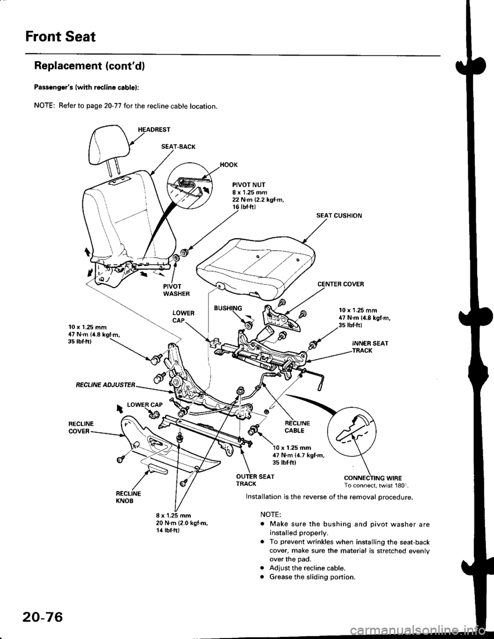
Front Seat
Replacement (cont'd)
Passenger's (with reclino cablel:
NOTE; Refer to page 20-77 for the recline cable location.
HEADREST
PIVOTWASHER
LOWERCAP
PIVOT NUT8 x 1.25 mm22 N.m 12,2 kgl.m,tbt.ftt
SEAT CUSHION
CENTER COVER
10 x 1,25 mm47 N.m (4.8 kgf.m,
10 x 1.25 mm47 N.m {4.8 kgf.m,3s tbt.ft)
INNER SEATTRACK
35 tbf.ftl
RECLINE ADJUSTEB
RECLINECOVER
i LowER CAP
bRECLINECABLE
x 1.25 mm47 N'm (4.7 kgf.m,35 tbtftl
SEAT
8 x 1.25 mm20 N.m {2.0 kgf.m,14 rbf.ft)
ruf, To connect, twist 180'.
lnstallation is the reverse of the removal procedure.
NOTE:
. Make sure the bushing and pivot washer are
installed properly.
. To prevent wrinkles when installing the seat-back
cover, make sure the material is stretched evenly
over the pad.
. Adjust the recline cable.
. G.ease the sliding ponion.
SEAT-BACK
20-76
Page 1307 of 2189
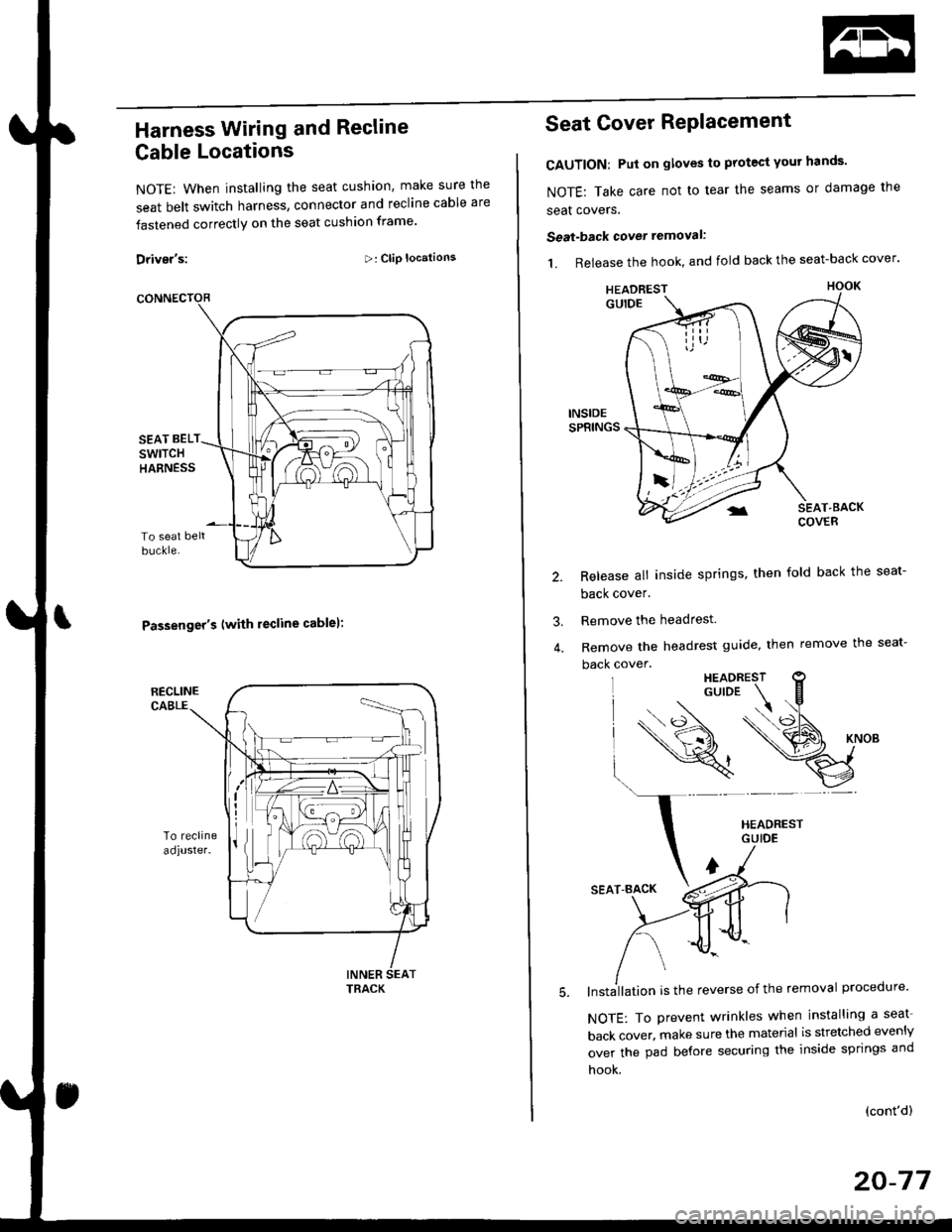
Harness Wiring and Recline
Cable Locations
NOTE: When installing the seat cushion, make sure the
seat belt switch harness, connector and recline cable are
fastened correctly on the seat cushion frame'
Driver's:>: Clip locations
Passenger's (with lecline cablel:
TRACK
Seat Cover RePlacement
CAUTION: Put on gloves to protest yout hands'
NOTE: Take care not to tear the seams or damage the
seat covers.
Seat-back cover removal:
1. Release the hook, and fold back the seat-back cover'
Release all inside springs, then fold back the seat-
back cover.
Remove the headrest.
Remove the headrest guide, then remove the seat-
back cover.
lnst;llation is the reverse of the removal procedure'
NOTE: To prevent wrinkles when installing a seat-
back cover, make sure the material is stretched evenly
over the pad before securing the inside springs and
hook.
3.
(cont'd)
20-77
HEADREST
Page 1308 of 2189
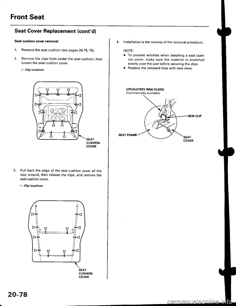
Front Seat
2.
1.
3.
CUSHIONCOVER
cover all the
remove the
Seat Cover Replacement (cont'd)
Seat cushion cover removal:
Remove the seat cushion {see pages 20,75,76).
Remove the clips from under the seat cushion, thenloosen the seat cushion cover.
>: Clip locataons
Pull back lhe edge of the seat cushion
way around, then release the clips, and
seat cushaon cover.
>: Clip locations
SEATCUSHIONCOVER
1-. v v vl
20-7A
4. Installation is the reverse of the removal procedure.
NOTE:
. To prevent wrinkles when installing a seat cush-ion cover, make sure the material is stretched
evenly over the pad before securing the clips.. Replace the released clips with new ones.
UPHOLSTERY RING PLIERS
NEW CLIP
SEAT FRAME
Page 1311 of 2189
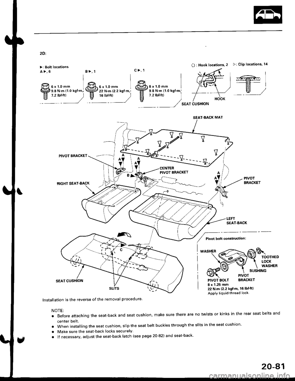
2Dt
>: Bolt locationsa>,6
O : Hook locations. 2 >: Clip location3, 14
SEAT CUSHION
,r@.''----EF-|
EH)w,/
PIVOTBRACKET
BUSXING
PIVOT
PIVOT BOLT BRACKET
I x 1 .25 mm22 N.m (2.2 kgt m. 16lblft)
Apply liquid thread lock.
lnstallation is the reverse of the removal procedure'
NOTE;
.Beforeattachingtheseat-backandseatcushion,makesuretherearenotwistsorkinksintherearseatbe|tsand
center belt.
.wheninsta||ingtheseatcushion,sliptheseatbe|tbucklesthroughthes|itsintheseatcushion.
. Make sure the seat-back locks securely
. lf necessary, adjust the seat-back latch (see page 20-82) and seat-back'
6xr.omm ]9.8 N.m l1.O kgf.m,i,:r:2
B>, 1
ffi
IgIt
c>, 1
6xr.omm I 8r.'r.o-- r22 N.m {2.2 kgtm,' \ffz s.e N.m tr.o *gf.m,'
,r:r",
_) E
7.2rbf.ftl
)
vv
PIVOT BRACKET
RIGHT SEAT.BACK
PIVOT BRACKET
Pivot bolt constauctaon:
TOOTHEDLOCKWASHER
SEAT.BACK MAT
,^
20-41
Page 1312 of 2189
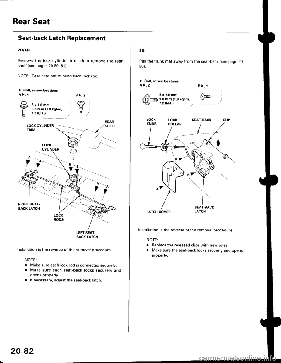
Rear Seat
Seat-back Latch Replacement
2Dl4Dl
Remove the lock cylinder trim, then remove the rear
shelf (see pages 20 59, 61).
NOTE: Take care not to bend each lock rod.
>: Boh, screw locationsA>,4
6x1.0mm9.8 N.m (1.0 kgt.m,7.2 rbf.ftl
LOCK CYLINOERTRIM
.i.-::
LOCKRODS
LEFT SEAT-EACK I-ATCH
Installation is the reverse of the removal procedure.
NOTE:
. Make sure each lock rod is connected securely.. [/ake sure each seat-back locks securely and
opens properly.
. lf necessary, adjust the seat-back latch.
B >,2
/+j
V
LOCKCYLINDER
20-8�2
3D:
Pull the trunk mat away from the seat'back (see page 20-
80).
>: Boll, screw locationsa>,2
6x1.0mm9.8 N.m (1.0 kgf.m,7.2 tbl.ft)
B>, 1
@
LATCH COVEB
Installation is the reverse ofthe removal procedure.
NOTE:
. Replace the released clips with new ones.. lvlake sure the seat-back locks securely and opensproperly.
SEAT"BACK
Page 1313 of 2189
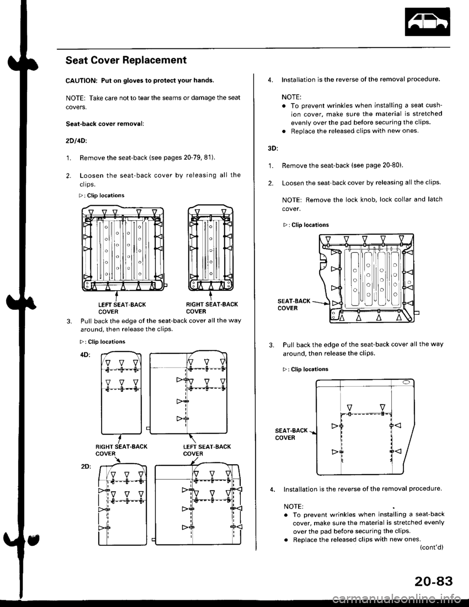
Seat Cover Replacement
CAUTION: Put on gloves to protact your hands,
NOTE| Take care not to tear the seams or damage the seat
covers.
Seat-back cover removal:
2D l4Dl
1. Remove the seat-back (see pages 20-79,8'1).
2. Loosen the seat-back cover by releasing all the
clrps.
>: Clip locations
LEFT SEAT-BACKCOVERRIGHT SEAT.EACKCOVER
3.Pull back the edge of the seat-back cover all the way
around. then release the clios.
>: Clip locations
RIGHT SEAT.BACK
1.
2.
4. Installation is the reverse of the removal procedure.
NOTE:
. To prevent wrinkles when installlng a seat cush-
ion cover. make sure the material is stretched
evenly over the pad before securing the clips.
. Replace the released clips with new ones
3D:
Remove the seat-back (see page 20-80).
Loosen the seat-back cover by releasing all the clips.
NOTE: Remove the lock knob, lock collar and latch
cover.
>: Clip locations
SEAT-BACKCOVER
3. Pull back the edge of the seat-back cover all the way
around, then release the cliPs.
>: Clip locations
SEAT.BACKCOVER
Installation is the reverse of the removal procedure.
NOTE:
. To prevent wrinkles when installing a seat-back
cover, make sure the material is stretched evenly
over the pad before securing the clips.
. Replace the released clips with new ones.(cont'd)
o
o
o
o
o
o
o
o
20-a3