100 HONDA CIVIC 2000 6.G Service Manual
[x] Cancel search | Manufacturer: HONDA, Model Year: 2000, Model line: CIVIC, Model: HONDA CIVIC 2000 6.GPages: 2189, PDF Size: 69.39 MB
Page 175 of 2189
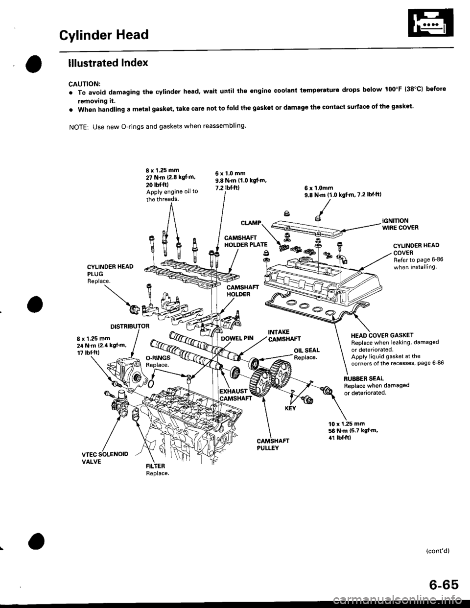
Cylinder Head
lllustrated Index
CAUTION:
. To avoid damaging the cylinder head, wait until the engine coolant tempsraturo drops below 100"F (38"C1 bofote
removing it,
. when handling a metal gasket, take caro not to fold the gaskot or damage the contact surface of the gasket.
NOTE: Use new O-rings and gaskets when reassembling.
CYLINDER HEAO
PLUGReplace.
)@
DISTRIBUTOR
8 x 1 ,25 mm
27 N.m P.E kgl m.
20 tbf.foApply engine oil to
the threads.
cr.rMp.S
CAMSHAFT A"o''*t*'; wes@
OIL SEALReplace.
6 x l,omm9.8 N'm tl.0 kgt'm,7.2lbf ft)
RUBBER SEALReplace when damaged
or detedorated.
6x1.0mm9.8 N.m (1.0 kgf'm,
7.2 rbnftl
fi%
IGNMONWIRE COVER
CYLINOER HEAD
COVERRefer to page 6-86
when installing
HEAD COVER GASKETReplace when leaking, damaged
or deteriorated.Apply liquid gasket at thecorners of the recesses, Page 6-86
8 x 1,25 mm24 N.m {2.4 kgf'm,
1? tbf.ftl
EXHAUST
10 x 1.25 mm56 N.m (5.7 kgf m,,r1 lbl.ft)
(cont'd)
6-65
Page 177 of 2189
Removal
Engine removal is not required for this procedure.
!@@ Make sure jacks and safety stands are placed
properly and hoist brackels are attached to correst posi-
tion on the engine,
CAUTION:
o Use fender covers to avoid damaging painted sur-
faces.
To avoid damage, unplug the wiling connectors
carelully while holding the connector portion.
To avoid damaging the cylinder head, wait until the
engine coolant temperature drops below 100"F {38'Cl
before loosening the retaining bolt.
NOTE:
. Unspecified items are common.
. Mark all wiring and hoses to avoid misconnection.
AIso, be sure that they do not contact other wiring or
hoses or interfere with other parts.
o Inspect the timing belt before removing the cylinder
n eao.
. Turn the crankshaft pulley so that the No. 1 piston is
at top dead center (see page 6-64).
1. Disconnect the negative terminal from the battery.
Drain the engine coolant {see page 10-7).
. Remove the radiator cap to speed draining.
Remove the strut brace (see page 5-2).
Remove the intake air duct and air cleaner housing
(see page 5-3).
Remove the adjusting bolt and mounting bolt, then
remove the power steering (P/S) pump belt and pump
(see page 5 5).
2.
3.
4.
\
ADJUSTING
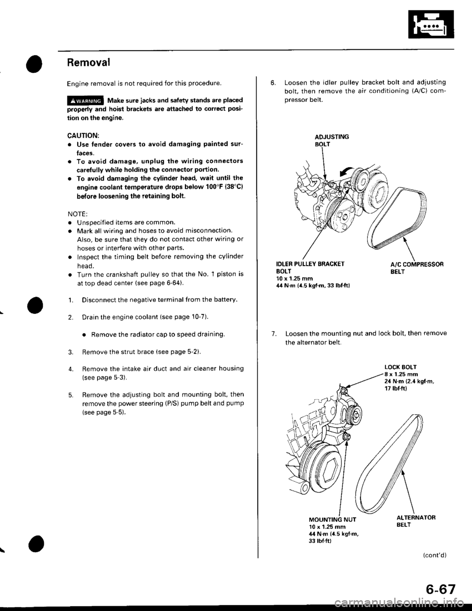
6. Loosen the idler pulley bracket bolt and adjusting
bolt, then remove the air conditioning (A/C) com-
pressor belt.
IDLER PULLEY BRACKETBOLT10 x 1.25 mm44 N.m {4.5 kg,l.m, 33 lbt.ft}
7. Loosen the mounting nut and lock bolt, then remove
the alternator belt.
LOCK BOLT8 x 1.25 mm24 N.m {2.4 kgf.m,17 tbtftl
ALTERNATORBELT10 x 1.25 mm,l,l N.m {4.5 kgf.m,33 tbf.ft,
(cont'd)
6-67
Page 187 of 2189
Valves, Valve Springs and Valve Seals
Removal
NOTE: ldentify valves and valve springs as they are
removed so that each item can be reinstalled in its origi-
nal Dosition.
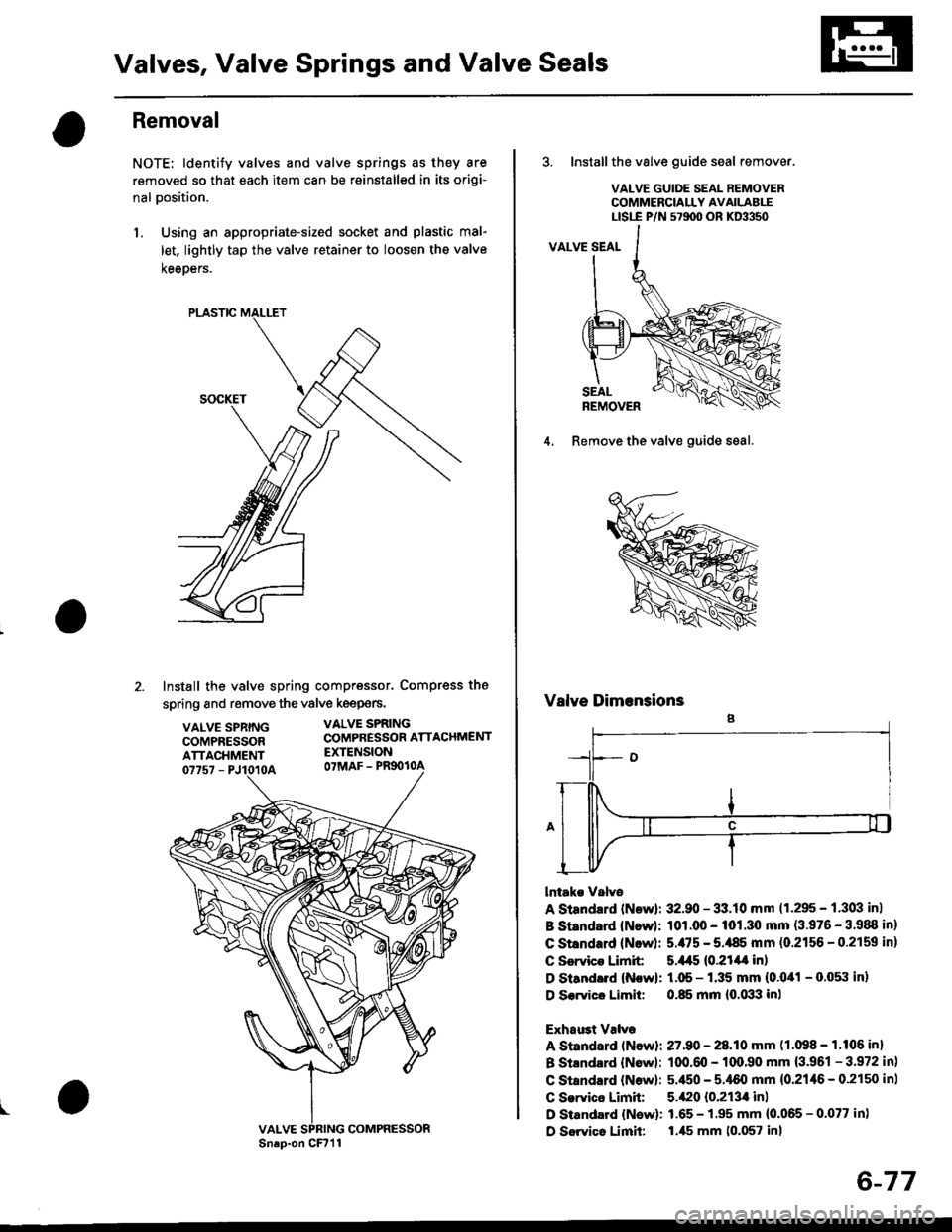
l. Using an appropriate-sized socket and plastic mal-
let, lightly tap the valve retainer to loosen the valve
keeoers.
PLASTIC
Install the valve spring compressor. Compress the
spring and remove the vSlve keepers.
VALVE SPRINGCOMPRESSORATTACHMENT07757 - PJ1010A
VALVE SPRINGCOMPRESSOR ATTACHMENTEXTENSIONOTMAF - PRgOIOA
I
Sn.p-on CFr1lCOMPRESSOR
6-77
3. Installthe valve guide seal remover.
VALVE GUIDE SEAL REMOVERCOMMERCIALLY AVAILABLELtst-E P/N 571100 ()R KD3350
4. Remove the valve guide seal.
Valve Dimensions
lntake Valvo
A Standsrd {Newl; 32.90 - 33.10 mm (1.295 - 1.303 in}
B St ndard {New}: 101.00 - 101.30 mm (3.976 - 3'988 in}
C Stsndard (Nowl: 5./t5 - 5.,185 mm (0.2156 - 0.2159 in)
C Servico Limit 5.445 {0.21/l| in)
D Siandard (N!w): 1.05 - 1.35 mm (0.041 - O.05il inl
D S€.vice Limit: 0.85 mm {0.033 inl
Exhaust Valve
A Standard lNewli 27.90 - 28.10 mm (1.098 - 1.106 in)
B Stlndard {Nowl: 100.m - 1qr,90 mm {3.961 - 3.972 in)
C Stsndard {Now}: 5.450 - 5.,[60 mm {0.21,16 - 0.2150 in)
C Service Limit 5.420 10.213,0 inl
D Standard {New): 1.65 - 1.95 mm (0.065 - 0.077 in)
D Sorvico Limit: l.ils mm 10.057 inl
Page 190 of 2189
t
Valve Guides
Replacement
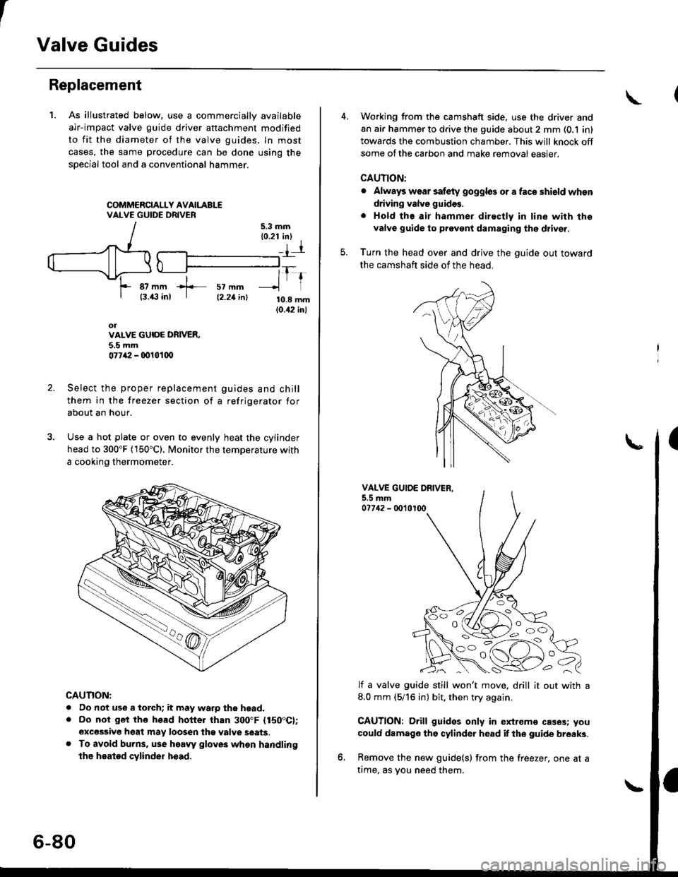
1. As illustrated below, use a commerciallv available
air-impact valve guide driver attachment modified
to fit the diameter of the valve guides. ln most
cases, the same procedure can be done using the
sDecial tool and a conventional hammer.
COMMERCIALLY AVAILABLEVALVE GUIDE DRIVER
87 mm -L- sz mm(3.43 inl I tz.zr int
rE-tt
10.8 mm10.42 inl
olVALVE GUIOE DRIVER,5.5 mm077,P - 0010100
Select the proper replacement guides and chill
them in the freezer section of a refrigerator for
about an hour.
Use a hot plate or oven to evenly heat the cylinder
head to 300"F (150"C). Monitor the temperature with
a cooking thermometer.
CAUTION:
. Do not use a torch; it may warp tho head.. Do not get tho head hotter than 300"F {150"C};excesgive heat may loosen thg valve seats.. To avoid burns. use haaw gloves whon handling
the heatod cylinder head.
6-80
Working from the camshaft side, use the driver and
an air hammer to drive the guide about 2 mm (0.1 in)
towards the combustion chamber. This will knock off
some ofthe carbon and make removaleasier.
CAUTION:
. Always wsar safety goggles or a face shield whsn
driving valve guides.
. Hold the air hammer dir€ctly in line with the
valve guide to prevont damaging thg dtiver.
Turn the head over and drive the guide out toward
the camshaft side of the head.
VALVE GUIOE DRIVER,5.5 mm077{2 - 0010100
lf a valve guide still won't move. drill it out with a8.0 mm (5/16 in) bit, then try again.
CAUTION: Drill guides only in extreme cases; you
could damago the cylinder head if ths guide br6aks.
Remove the new guide(s) from the freezer, one at a
time, as vou need them.
-:^-,65i^q
NNSp-<
Page 199 of 2189
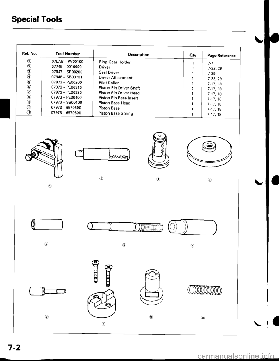
Special Tools
Ref. No. I Tool Numbel
o
aal
@
o
@6'
@
o
07LAB - PV00100
07749 - 0010000
07947 - SB00200
07948 - SB00'101
07973 - PE00200
07973 - PE00310
07973 - PE00320
07973 - PE00400
07973 - S800100
07973 - 6s70500
07973 - 6570600
Ring Gear Holder
Driver
Seal Driver
Driver Attachment
Pilot Collar
Piston Pin Driver Shaft
Piston Pin Driver Head
Piston Pin Base Insert
Piston Base Head
Piston Base
Piston Base Spring
1-7
7-22,29
7.29
7-22,29
7-17,18'7 -17, 1a
7-11, 1A
7 -17, 18
1-17, 18
7-17,18
7-17,18
Y(\!
a.:
ai
C
a
Eg
ot0arll
a
7-2
\
Page 215 of 2189
Connecting RodsPiston Pins
Selection
Each rod falls into one of four tolerance ranges {from O to+ 0.024 mm (0 to + 0.0009 in), in 0.006 mm (0.0002 in)increments) depending on the size of its big end bore. lt,sthen stamped with a number {1, 2,3, or 4) indicating therange.
You may find any combination ot l, 2, 3, or 4 in any
engrne.
Normal Eore Size: 48.0 mm (1.89 in)
NOTE:
o Reference numbers are for big end bore size and doNOT indicate the position of the rod in the engine.. Inspect connecting rod for cracks and heat damage.
CONNECTING ROD AOREREFERENCE NUMBERHalf of number is stamped onbearing cap, the other half onconnectrng rod.
7-18
Installation
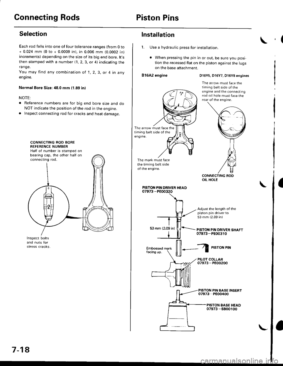
1. Use a hydraulic press for installation.
. When pressing the pin in or out, be sure you posi
tion the recessed flat on the piston against the lugson the base attachment.
816A2 engine
The arrow must face thetiming belt side of theeng Ine.
The mark must facethe timing belt sideof the engine.
D16Y5, D16Y7, O16Y8 engines
The arrow must face thetiming belt side o{ theengine and the connectingrod oil hole must face therear of the engine.
Adjust the length of thepiston pin driver to53 mm (2.09 4n)
PISTON PIN DRIVER SHAFT07973-PEOo3r0
PISTON PIN DRIVER HEAD
il--Z
P,"roNPrN
PILOT COLLAR07973-PE00200
PISTON PIN BASE INSERT07973 PEO0400
PISTON EASE HEAO07973 -5800100
,(
a
Page 219 of 2189
Piston RingsCrankshaft Oil Seal
Alignment (cont'dl
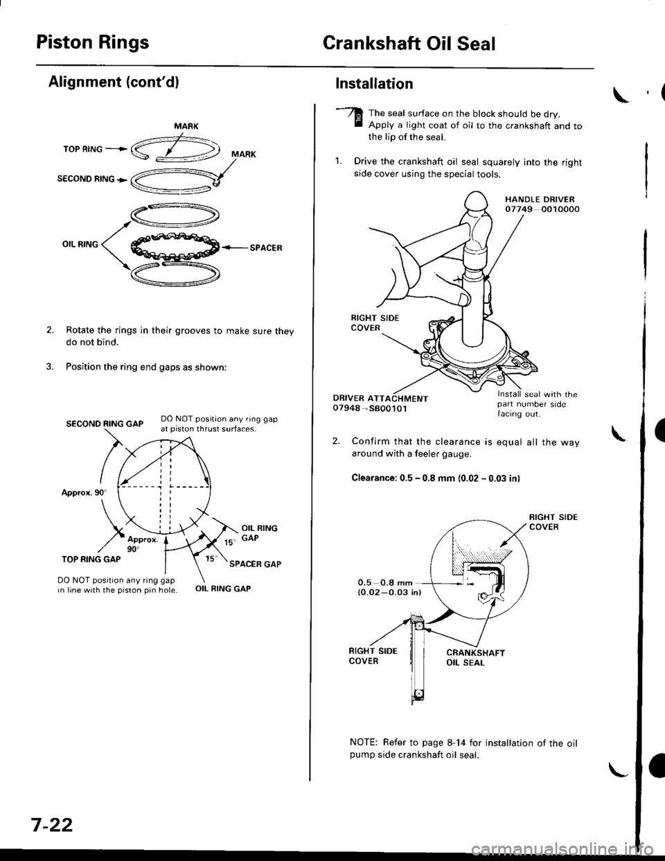
TOP RING ---.>
SECOND RING >
MARK
,a-)
/\_4
o,.r^o( qffi<--sPACER
\Z-.
v
Rotate the rings in their grooves to make sure theydo not bind.
Position the ring end gaps as shown:
DO NOT position any ring gapat piston thrust surfaces.
DO NOT position any ring gapin line with the piston pin hole.OIL RING GAP
SECOND RING GAP
Approx.90
TOP RING GAP
7-22
Installation
The seal surface on the block should be dry.Apply a light coat of oil to the c.ankshaft and tothe lip of the seal.
1. Drive the crankshaft oil seal squarely into the right
side cover using the special tools.
HANDLE DRIVER07749 0010000
seal with thepan number sidefacing out.
Confirm that the clearance is equal all the way
around with a feeler gauge.
Clearance:0.5 - 0.8 mm (0.02 - 0.03 inl
NOTE: Refer to page 8-14 for installation of the oilpumo side crankshaft oil seal.
,(
\
Page 226 of 2189
Oil Seals
lnstallation
NOTE:
. Engine removal is not required.
. The crankshaft oil seal housing should be dry.
Apply a light coat of grease to the crankshaft and to
the lips of the seals.
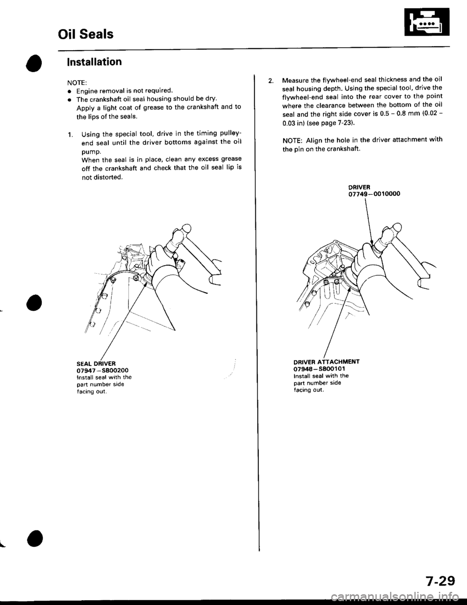
1. Using the special tool, drive in the timing pulley-
end seal until the driver bottoms against the oil
pump.
When the seal is in place, clean any excess grease
off the crankshaft and check that the oil seal lip is
not distorted.
07947 -S800200
lnstall seal with thepart number sadefacing out.
I
2. Measure the flvwheel-end seal thickness and the oil
seal housing depth. Using the special tool. drive the
flywheel-end seal into the rear cover to the point
where the clearance between the bottom of the oil
seal and the right side cover is 0.5 - 0.8 mm (0.02 -
0.03 in) (see page 7-23).
NOTE: Align the hole in the driver attachment with
the Din on the crankshaft.
DRIVER ATTACHMENT0794a-s800101lnslall seal with thepart number sidefacing out.
DRIVER07749-0010000
7 -29
Page 228 of 2189

Special Tools
Ref. No. I Toot Number
07746 - 0010400
07749 - 0010000
07912 - 6110001
Attachment, 52 x 55 mmDriver
Oil Filter Wrench
o6\,6
\
ll
a
8-2
\
Page 234 of 2189
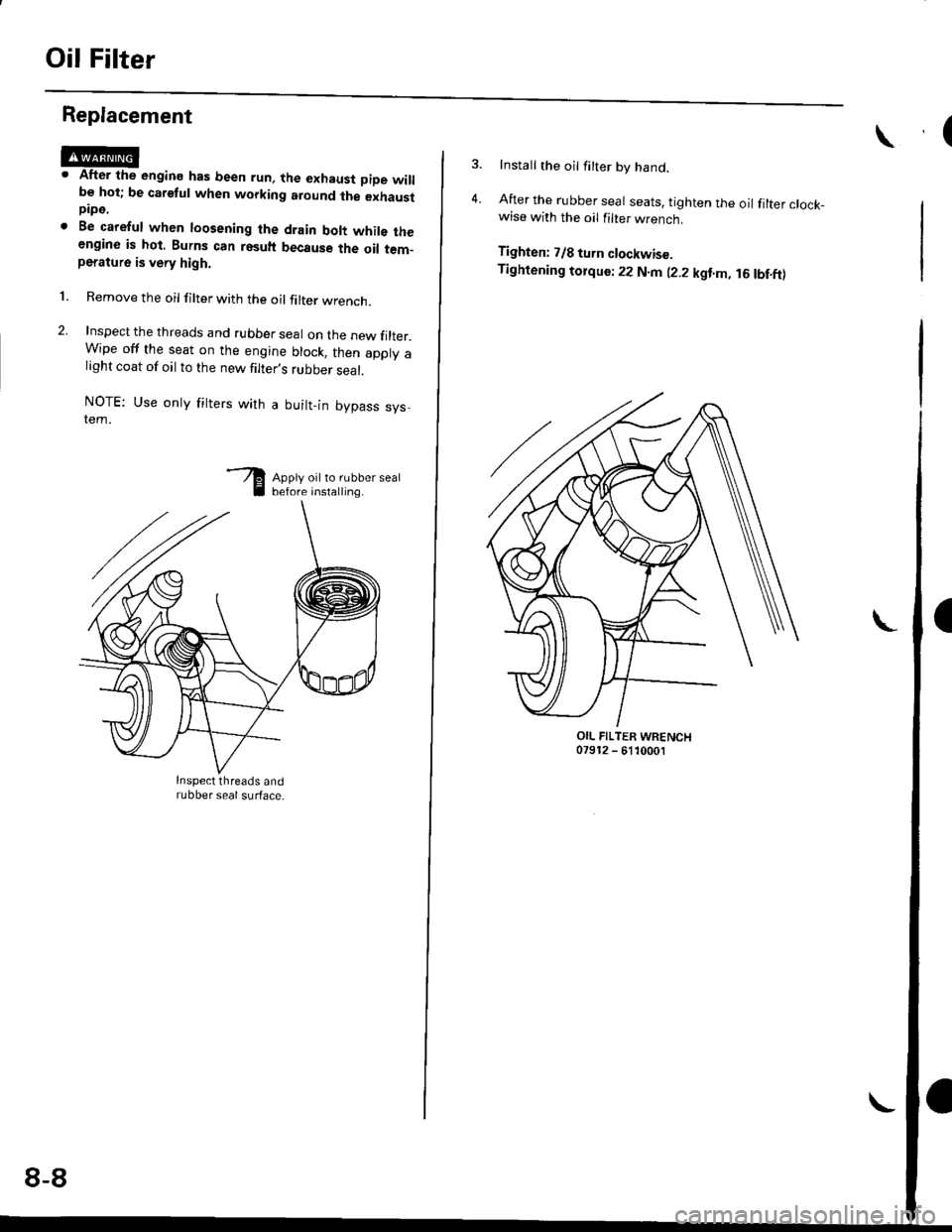
Oil Filter
Replacement
After the engine has been run, the exhaust pipe willbe hot; be careful when working around ihe exhaustpipe.
Be careful when loosening the drain bolt whils theengine is hot. Burns can resuh because the oil tem-peratu16 is very high.
Remove the oil filter with the oil filter wrencn.
Inspect the threads and rubber seal on the new filter.Wipe off the seat on the engine block, then apply alight coat of oil to the new filter,s rubber seal.
NOTE: Use onty fitters with a built-in bypass sys,tem.
Apply oil to rubber sealbefore installing.
l.
Inspect threads andrubber seal surface.
8-8
Install the oil filter by hand.
After the rubber seal seats, tighten the oil filter clock_wise with the oil filter wrench.
Tighten: 7/8 tu.n clockwise.
Tightening tolque: 22 N.m (2.2 kgt.m, 16lbf.ft)
OIL FILTER WRENCH07912 - 6110001