100 HONDA CIVIC 2000 6.G Repair Manual
[x] Cancel search | Manufacturer: HONDA, Model Year: 2000, Model line: CIVIC, Model: HONDA CIVIC 2000 6.GPages: 2189, PDF Size: 69.39 MB
Page 271 of 2189
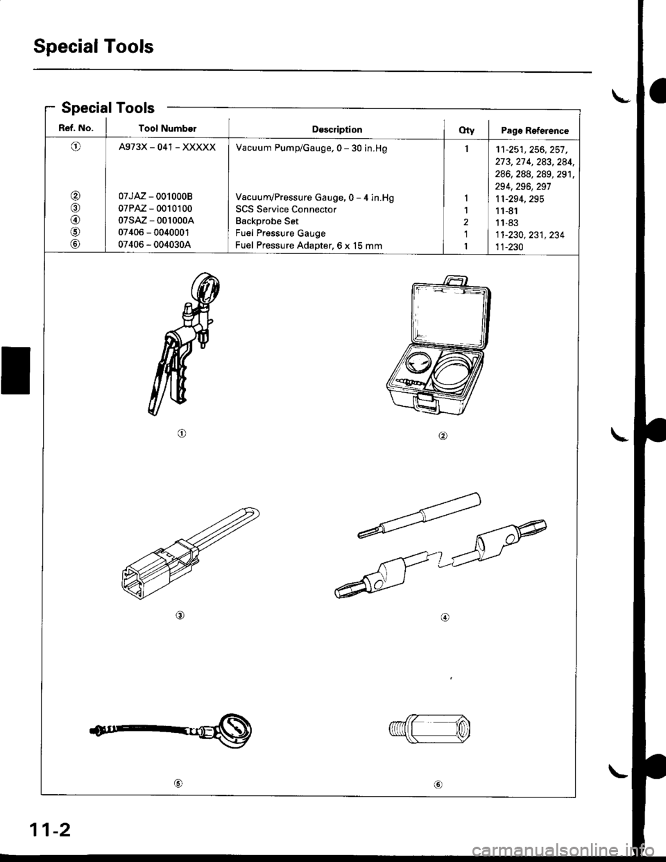
Special Tools
a\-Special Tools
R€f. No. I Tool NumberDsscriptionOty I Pagr Reference
O
@/n
@
@
@
A973X_041 _ XXXXX
07JAZ - 0010008
07PAZ - 0010100
07sAz - 001000A
07406 - 0040001
07406 - 0040304
Vacuum Pump/Gauge, 0 - 30 in.H9
Vacuum/Pressure Gauge, 0 - 4 in.Hg
SCS Service Connector
Backprobe Set
Fuel Pressure Gauge
Fuel Pressure Adapter,6 x 15 mm
I
I
1
2
1
I
11-251,256, 257 ,273,27 4, 283,284,
286, 288, 289, 291,
294,296,297
11-294,295
11-81
11-83
1't-230, 231, 234
11-230
ta
1n\Y
11-2
Page 350 of 2189
Troubleshooting
Troubleshooting Procedures
How To Begin Troubleshooting
When the Malfunction Indicator Lamp (MlL) has been reported on, or there is a driveability problem, use the appropr'-
ate orocedure below to diagnose and repair the problem'
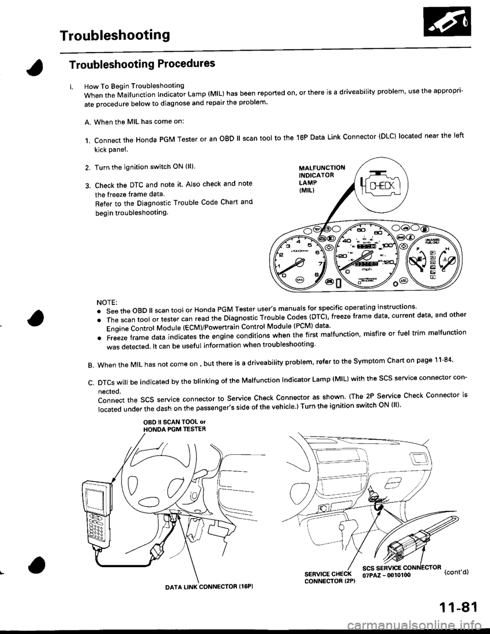
A. When the MIL has come on:
,1. connect the Honda PGM Tester or an oBD ll scan tool to the 16P Data Link connector (DLC) located near the left
kick panel.
2. Turn the ignition switch ON (ll)
3. Check the DTC and note it. Also check and note
the freeze trame data
Refer to the Diagnostic Trouble Code Chart and
begin troubleshooting.
NOTE:
.SeetheoBD||scantoolorHondaPGMTesteruser,smanua|sforspecificoperatinginstructions..
.Thescantoo|oltestercanreadtheDiagnosticTroub|ecodes(DTc},freezeframedata,currentdata,andother
Engine Control Module (ECM)/Powertrain Control Module (PCM) data'
oFreezeframedataindicatestheengineconditionswhenthefirstma|function,misfireorfue|trimma|function
was detected. lt can be useful information when troubleshooting'
B. When the MIL has not come on , out there is a d riveability problem, refer to the Symptom Chart on page 1 1-84'
c.DTcswi|lbeindicatedbytheb|inkingoftheMa|function|ndicatorLamp(M|L)withthescsserviceconnectorcon.
nected.
Connect the SCS service connector to Service Check Connector as shown (The 2P Service Check Connector is
|ocatedunderthedashonthepassenger,ssideofthevehic|e')TurntheignitionswitchoN{||)'
OBO ll SCAN TOOL olHONOA PGM TESTER
SERVICE CHECKCONNECTOR I2P)
scs sERvlcE(cont'd)
MALFUNCTIONINDICATORLAMP
DATA LINK CONNECTOR Il6PI
07PAZ - (x)l0100
11-81
Page 352 of 2189
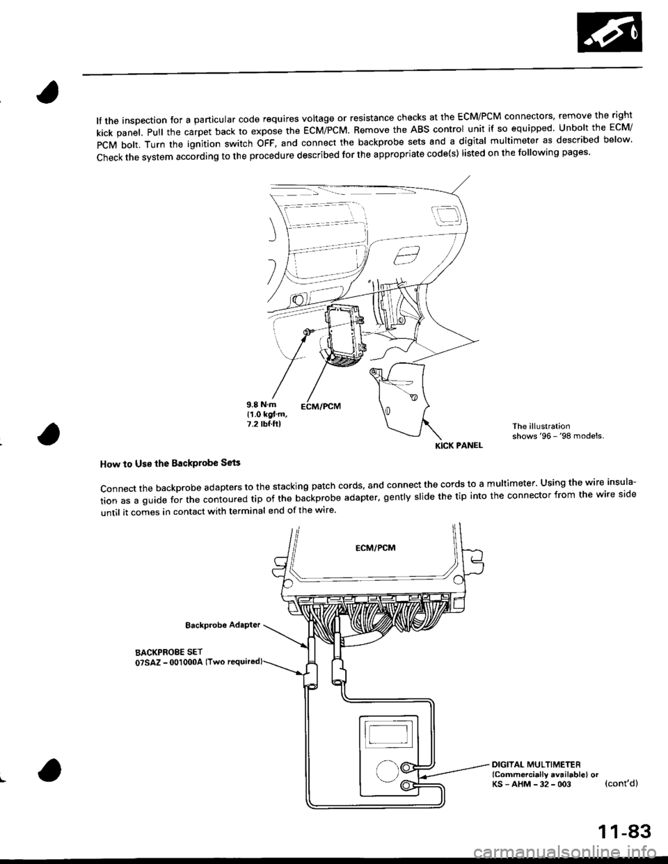
lf the inspection for a particular code requires voltage or resistance checks at the ECM/PCM connectors, remove the right
kick panel. Pull the carpet back to expose the ECM/PCM. Remove the ABS control unit if so equipped. unbolt the EcM/
PCM bolt. Turn the ignition switch oFF, and connect the backprobe sets and a digital multimeter as described below
check the system according to the procedure described for the appropriate code(s) listed on the following pages'
The illustrationshows '96 - '98 models.
How to Use lhe Backprobe Sets
connect the backprobe adapters to the stacking patch cords, and connect the cords to a multimeter. using the wire insula-
tion as a guide for the contoured trp of the backprobe adapter. gently slide the tip into the connector from the wire side
until it comes in contact with terminal end of the wire'
BackProbe
BACKPROEE SET
07SAZ - 001000A lTwo
DIGITAL MULTIMETER(Commercially avail.bleI orKs - AHM - 32 - oo3 (cont'd)
KICK PANEL
1 1-83
Page 369 of 2189
Troubleshooting
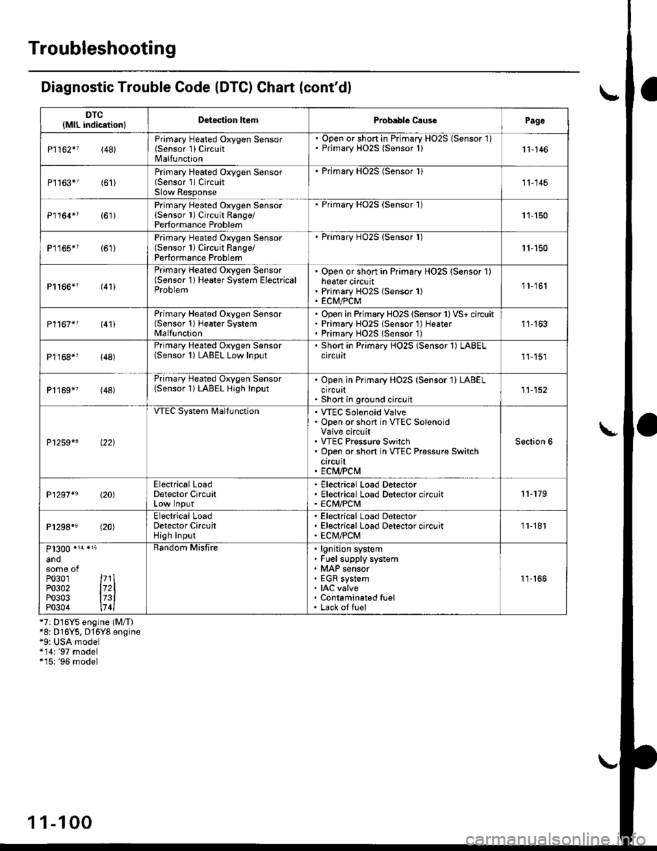
Diagnostic Trouble Code (DTGI Chart (cont'dl
*7: D16YS engine (M/T)*8: D16Y5, D'16Y8 engine*9: USA model*14r'97 model*15r '96 model
DTC(MlL indicationlDetection lt6mProbablc CausePage
P1162+1 (48)Primary Heated Oxygen Sensor(Sensor 1) CircuitMalfunction
Open or short in Primarv HO2S (Sensor 1Primary H02S (Sensor 1)1 1- 146
P]163' (61)Primary Heated Oxygen Sensor(Sensor '1) CircuitSlow Response
. Primary HO2S (Sensor 1)
11-145
Pl164*r (61)Primary Heated Oxygen Sensor(Sensor l) Cjrcuit Range/Performance Problem
. Primary HO2S (Sensor 1)
1 1- 150
P1165*? (61)Primary Heated Oxygen Sensor(Sensor 1) Circuit Range/Performance Problem
. Primary HO2S (Sensor 1)
11-150
P1166' (41i
Primary Heated Oxygen Sensor(Sensor '1) Heater System ElectricalProblem
Open or short in Primary HO2S (Sensor 1)heater circuitPrimary HO2S (Sensor 1)ECM/PCM
1 1-'161
P1167*' (41)Primary Heated Oxygen SensorlSensor 1) Heater SystemMalfunction
Open in Primary HO2S (Sensor 1) VS+ circuitPrimary HO2S (Sensor 1) HeaterPrimarv HO2S {Sensor 1)1 1- 163
P1168*' (48)Primary Heated Oxygen Sensor(Sensor 1) LABEL Low Input
. Short in Primary HO2S (Sensor 1) LABELcircuit11-151
Pl169*? (48)
Primary Heated Oxygen Sensor(Sensor 1)IABEL High Input. Open in Primary HO2S (Sensor 1)IABELcircuit. Short in ground circuit11.152
P1259*3(221
WEC System MalfunctionWEC Solenoid ValveOpen or short in WEC SolenoidValve circu itVTEC Pressure SwitchOpen or short in VTEC Pressure SwitchcircuitECM,FCM
Section 6
P1297*s (20)Electrical LoadDetector CircuitLow Input
Electrical Load DetectorElectrical Load Detector circuitECM/PCM11-179
Pr298+' l20l
Electrical LoadDetector CircuitHigh Input
Electrical Load DetectorElectrical Load Detector circuitECM/PCM1 1-181
anosome ofP0301P0302P0303P0304
l71ll72ll73ll7 4l
Bandom Misfirelgnition systemFuel supply systemMAP sensorEGR systemIAC valveContaminated fuelLack ol fuel
11-166
1 1-100
Page 374 of 2189
3.
5.
6.
1.
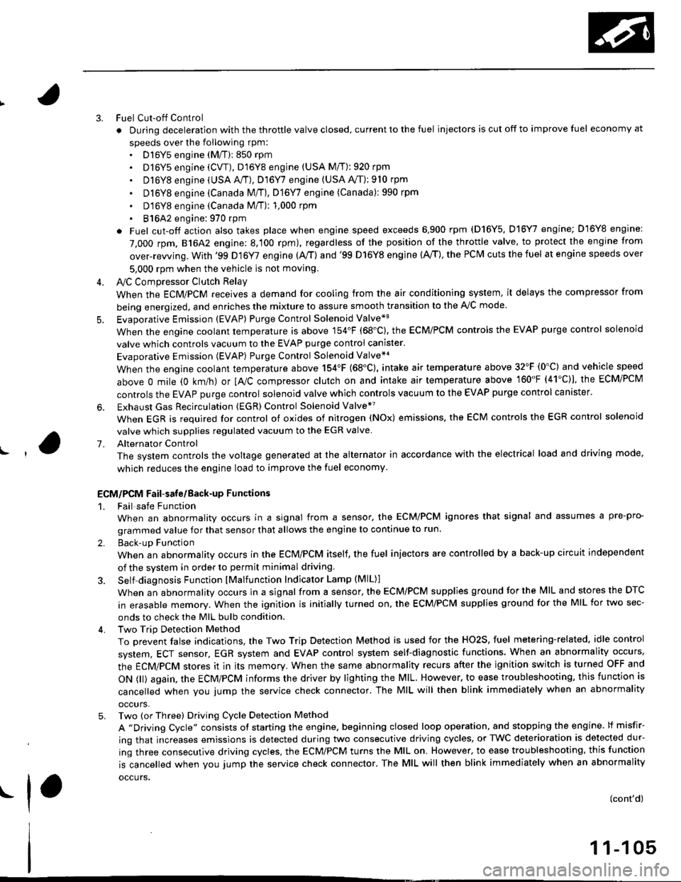
Fuel Cut-off Control
. During deceleration with the throttle valve closed, current to the fuel injectors is cut off to improve fuel economy at
speeds over the following rpm:. D16Y5 engine (M/T):850 rpm. D]6Y5 engine (CVT), D'16Y8 engine (USA M/T): 920 rpm
. Dl6Y8 engine (USA A,/I), D16Y7 engine (USA A,/T);910 rpm
. D16Y8 engine (Canada M/T), D16Y7 engine (canada): 990 rpm
' D16Y8 engine (Canada M/T): 1,000 rpm
. 816A2 engine: 970 rpm
. Fuel cut-off action also takes place when engine speed exceeds 6,900 rpm (D16Y5, D16Y7 engine; D'16Y8 engine:
7,000 rpm. 816A2 engine: 8.100 rpm), regardless of the position of the throttle valve, to protect the engine from
over-rewing. With '99 Dl6Y7 engine (A,/T) and '99 D16Y8 engine (A./T), the PCM cuts the fuel at engine speeds over
5,000 rpm when the vehicle is not moving.
IVC Compressor Clutch Relay
When the ECM/PCM receives a demand for cooling from the air conditioning system, it delays the compressor from
being energized, and enriches the mixture to assure smooth transition to the A,/C mode
Evaporative Emission (EVAP) Purge Control Solenoid Valve*'
When the engine coolant temperature is above 154'F (68'C). the ECM/PCM controls the EVAP purge control solenoid
valve which controls vacuum to the EVAP purge control canister.
Evaporative Emission (EVAP) Purge Control Solenoid Valve*a
When the engine coolant temperature above 154"F (68"C), intake air temperature above 32"F (0'C) and vehicle speed
above 0 mile (0 km/h) or [Ay'C compressor clutch on and intake air temperature above 160"F (41'C)], the ECM/PCM
controls the EVAP purge control solenoid valve which controls vacuum to the EVAP purge control canister.
Exhaust Gas Recirculation (EGR) Control Solenoid Valve*?
When EGR is required for control of oxides of nitrogen (NOx) emissions. the ECM controls the EGR control solenoid
valve which supplies regulated vacuum to the EGR valve
Alternator Control
The system controls the voltage generated at the alternator in accordance with the electrical load and driving mode,
which reduces the engine load to improve the fuel economy.
ECM/PCM Fail-safe/Back-up Functions
1. Fail safe Function
When an abnormality occurs in a signal from a sensor, the ECM/PCM ignores that signal and assumes a pre-pro-
grammed value for that sensor that allows the engine to continue to run.
2. Back-uD Function
When an abnormality occurs in the ECM/PCM itself, the fuel injectors are controlled by a back-up circuit independent
of the system in order to permit minimal driving.
3. Self diagnosis Function lMalfunction Indicator Lamp (MlL)l
When an abnormality occurs in a signal from a sensor, the ECM/PCM supplies ground for the lvllL and stores the DTC
in erasable memory. When the ignition is initially turned on, the ECM/PCM supplies ground for the MIL for two sec-
onds to check the MIL bulb condition.
4. Two Trip Detection Method
To prevent false indications, the Two Trip Detection Method is used for the HO2S, fuel metering-related. idle control
system, ECT sensor, EGR system and EVAP control system self-diagnostic functions. When an abnormality occurs,
the ECM/PCM stores it in its memory. When the same abnormality recurs after the ignition switch is turned OFF and
ON 0l) again, the ECM/PCM informs the driver by lighting the MlL. However, to ease troubleshooting, this function is
cancelled when you jump the service check connector. The MIL will then blink immediately when an abnormality
occurs,
5. Two (or Three) Driving Cycle Detection Method
A "Driving Cycle" consists ot starting the engine. beginning closed loop operation, and stopping the engine. lf misfir-
ing that increases emissions is detected during two consecutive driving cycles, or TWC deterioration is detected dur-
ing three consecutive driving cycles, the ECM/PCM turns the MIL on. However, to ease troubleshooting, this function
is cancelled when you jump the service check connector. The MIL will then blink immediately when an abnormality
occurs.
(cont'd)
1 1-1 05
.1.
Page 393 of 2189
PGM-FI System
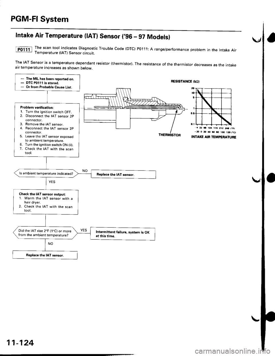
Intake Air Temperature (lAT) Sensor ('96 - 97 Models)
The scan tool indicates Diagnostic Trouble code (DTC) P0111: A range/performance problem in the lntake AarTemperature (lAT) Sensor circuit.
The IAT sensor is a temperature dependant resistor (thermistor). The resistance of the thermistor decreases as the intakeair temperature increases as shown below.
RES|STAI{CE {tol
. 32 .. ro. tr. 2r, zaa r..l-20 o 20 /|o ao ao 100 rrotlcl
INTAIG AIR TEMPEMTURE
- The MIL hss beon reported on.- DTC P0111 is stored.- Or from Probable C.use List.
Problem verification:1. Turn the ignition switch OFF.2. Disconnect the IAT sensor 2Pconnector,3. Remove the IAT sensor.4. Reconnect the IAT sensor 2p
5. Leave the IAT sensor exposedto ambaent temperature,6. Turn the ignition switch oN fll).7. Check the IAT with the scantool.
Rsplscg the IAT sensor.
Check tho IAT sensor output:1. Warm the IAT sensor with ahair dryer-2. Check the IAT with the scantool.
Did the IAT rise 2"F (1.C) or morefrom the ambient temperature?Int€rmittont failu.e, system is OKat this time.
Replsce the IAT sensor.
11-124
Page 400 of 2189
PGM-FI System
t
I
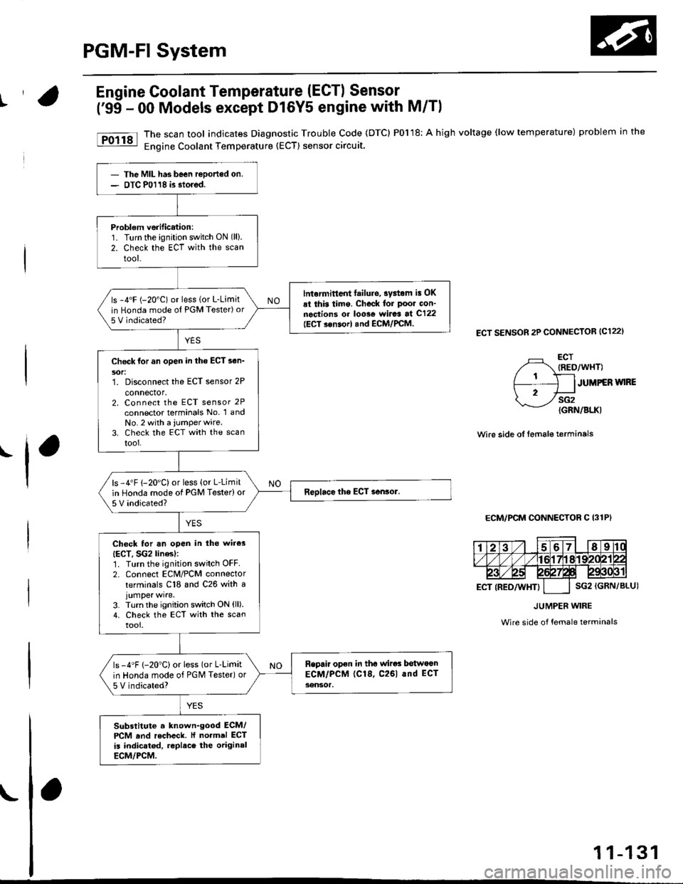
Engine Coolant Temperature (ECT) Sensor
('99 - 00 Models except Dl6Y5 engine with M/Tl
The scan tool indicates Diagnostic Trouble Code (DTC) P0118: A high voltage (low temperature) problem in the
Engine Coolant Temperature (ECT) sensor circuit.
ECT SENSOR 2P CONNECTOR {C122)
ECT(RED/Wr{T)
JUMPER IVIRE
sG2{GRN/BLK)
wire side of female terminals
ECM/PCM CONNECTOB C 131PI
The MIL has been reported on,
oTC P0118 is stored.
Problem verilication:1. Turn the ignition switch ON (ll).
2. Check the ECT with the scan
tool.
lntormittent failuro, systom is OK
at thb timo. Check lor poor con'nections or 10036 wiraa at C122
{ECT ssnsorl and ECM/rcM.
ls -4'F (-20"C) or less lor L-Limit
in Honda mode o{ PGM Tester) or
5 V indicated?
Check for an open in the Efi sen'
sori1. Disconnect the ECT sensor 2P
connector,2. Connect the ECT sensor 2P
connector terminals No, 1 andNo. 2 with a jumper wire.3. Check the ECT with the scantool.
ls -4"F 1-20"C) or less (or L-Limit
in Honda mode of PGM Tester) or
5 V indicated?
Check for sn open in the wires
IECT. SG2 linesl:1. Turn the ignition switch OFF.2. Connect ECM/PCM connectorterminals C18 and C26 with ajumper wire.3. Turn the ignition switch ON (ll).
4. Check the ECT with lhe scantooi.
Rspair opon in th6 wiros bstwoon
ECM/PCM (Cl8, C26l and ECT
3ensot.
ls -4'F {-20"C) or less (or L-Limit
in Honda mode of PGN4 Tester) or
5 V indicated?
Substitute 6 known-good ECM/PCM and recheck. l{ no.mal EcT
is indicatod, .eplace the originalECM/PCM.
JUMPER WIRE
Wire side of female terminals
11-131
Page 441 of 2189
PGM-FI System
tFos3sl
tFffi6l
tPr361 I
fPfi62l
fFr38il
tF13s2-l
Crankshaft Position/Top Dead Genter/Gylinder Position (CKP/TDC/CYP) Sensor
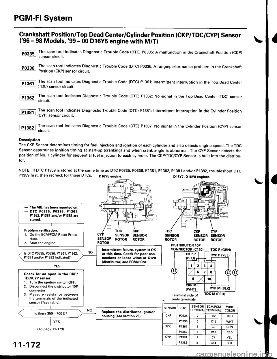
('96 - 98 Models, '!n - 00 D16Y5 engine with M/Tl
The scan tool indicates Diagnostic Trouble Code (DTC) P0335: A malfunction in the Crankshaft position (CKp)
sensor circuit.
The scan tool indicates Diagnostic Trouble Code (DTC) P0336: A range/performance problem in the CrankshaftPosition (CKP) sensor circuit.
The scan tool indicates Diagnostic Trouble Code (DTC) P1361: Intermittent interruotion in the Too Dead Center(TDC) sensor circuit.
The scan tool indicates Diagnostic Trouble Code {DTC) P1362: No signal in the Top Dead Center (TDC} sensorcircuit.
The scan tool indicates Diagnostic Trouble Code (DTC) P1381: Intermittent interruption in the Cvlinder Position{CYP) sensor circuit.
The scan tool indicates Diagnostic Trouble Code {DTC) Pl382: No signal in the Cylinder Position (CYP} sensorcircuit.
Description
The CKP Sensor determines timing for fuel injection and ignition of each cylinder and also detects engine speed. The TDCSensor determines ignition timing at start-up (cranking) and when crank angle is abnormal. The Cyp Sensor detects theposition of No. 1 cylinder for sequential fuel injection to each cylinder. The CKP/TDC/CYP Sensor is built into the distribu-ror.
NOTE: lf DTC P1359 is stored atthesametime as DTC P0335. P0336, P1361, Pl362, P1381 and/or P1382, troubteshoor DTCP1359 first, then recheck for those DTCS. Ot6y5 6ngine: Dt6y7, ot6y8 enqin6s:
SENSORBOTOR
TDCSENSORCKPSENSORSENSORROTORSENSORROTORSENSORROTORROTORROTOR
DISTRIBUTOR 1OPcoNNECTOR tC120tTDC P
- The MIL hrs been reported on.- DTC P0335, P0336, P1361,P1362, P1381 and/or Pl382 6restored,
Problem verification:1. Do the ECM/PCM Reset Proce-dure.2. Stan the engine.
Intermittent hilu.e, system b OKat this time. Check tor poor con-n€ctions or 10036 wiros at C120{distributor} and ECM/PCM.
ls DTC P0335, P0336, P1361, P1362,P1381 and/or P'l382 indicated?
Check for an open in the CKP/TDC/CYP sensor:1. Turn the ignition switch OFF.2. Disconnect the distributor 10P
3. Measure resistance betweenthe terminals of the indicatedsensor (*see table).
Replace the distributor ignitionhousing (soe section 23).ls there 350 - 700 0?
CYP M {BLK}
SENSORDTCSENSORIERMINATECMfCMTERMINATCOLOR
CKPP033s
m336
2c2BLU
6c12
TDCP1361
P1362
3GRN
7cl3RED
CYPP!381
P't382
c4YEL
8c148LK11-172
Page 527 of 2189
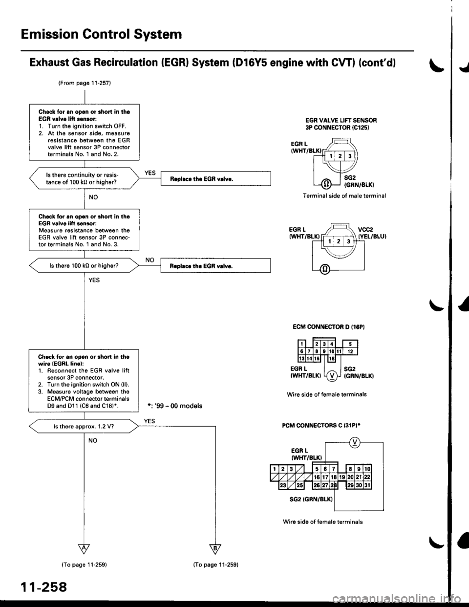
Emission Gontrol System
Exhaust Gas Recirculation (EGRI System (Dl6Y5 engine with CW) (cont'dl
EGR VALVE LIFT SENSOR3P CONNECTOR {Cl251
./
EGR L(WHT/BLKI
EGR LIWHT/BLKI
EGR L{WHT/BLKI
sG2
{GRN/BLK}
sG2{GRN/BLK}
Terminal side ol male terminal
ECIT'I CONNECTOR D II6PI
Wir€ side of f€male terminals
PCM CONNECTORS C (31PI*
{To page 11-259)
11-258
{From page 11-257}
Chock lor an opcn or short in th.EGR v.lve lift .€nsor'1. Turn the ignition switch OFF.2. At the sensor sid€, measur€resistance between the EGRvalve lift sensor 3P connectorterminals No. 1 and No.2.
ls there continuity or resis'tance ot 100 k0 or higher?
Chock tor sn op€n or lhort in theEGR valve lift lonror:Measure resistancg between theEGR valve lift s€nsor 3P connec-tor terminals No. 1 and No. 3.
ls there 100 k0 or higher?
Ch.ck tor an ooon or rhon in thcwiro IEGRL linc):1. Beconnect tho EGR v6lve liftsensor 3P connector.2. Turn tho ignition switch ON (ll).
3. Measure voltage between theECM/PCM connector terminalsD9 and Dl1 (C6 and C18l*.
ls there approx. 1.2 V?
(To page 11-259)
Wire side of female terminals
Page 531 of 2189
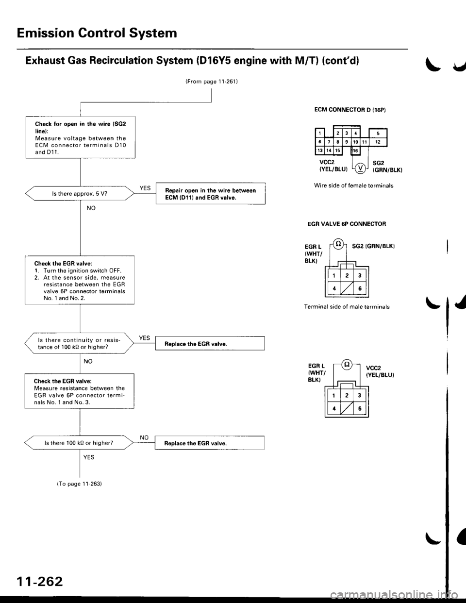
Emission Control System
(From page 11-261)
Check tor open in the wire (SG2
linel:Measure voltage between theECM connector terminals D10and D11.
Repsir open in lhe wire beiweenECM lOllland EGR valve.ls there approx. 5 V?
Check the EGR valve:1. Turn the ignition switch OFF.2, At the sensor side, measureresistance between the EGRvalve 6P connector terminalsNo. 1 and No. 2.
ls there continuity or resis-tance of 100 k0 or higher?
Check the EGR valve:Measure resistance between theEGR valve 6P connector terminals No. 1 and No.3.
ls there 100 k0 or higher?
Exhaust Gas Recirculation System (D16Y5 engine with M/T) (cont'dl
ECM CONNECTOR D {16P)
vcc2(YEL/BLU)
\v
sG2IGRN/BLK)
Wire side of female term;nals
EGR VALVE 6P CONNECTOR
EGR L(WHT/
BLK}
SG2 (GRN/BLK)
Termanal side of male terminals'l'
EGR L{WHT/BLK}
vcc2
{YEL/BLU}
(To pase 11 263)
1-262