100 HONDA CIVIC 2000 6.G Manual PDF
[x] Cancel search | Manufacturer: HONDA, Model Year: 2000, Model line: CIVIC, Model: HONDA CIVIC 2000 6.GPages: 2189, PDF Size: 69.39 MB
Page 611 of 2189
I
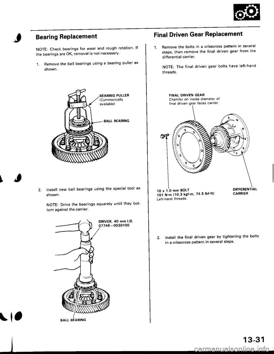
Bearing RePlacement
NOTE: Check bearings for wear and rough rotation lf
the bearings are OK, removal is not necessary'
'1. Remove the ball bearings using a bearing puller as
shown.
EALL B€ARING
lnstall new ball bearings using the special tool as
shown.
NOTE: Drive the bearings squarely until they bot-
tom against the carrler.
DRIVER, 40 mm LD.?746 -0030100
\1,
Final Driven Gear RePlacement
1, Remove the bolts in a crisscross pattern in several
steps, then remove the final driven gear from the
ditferential carrier'
NOTE: The final driven gear bolts have left-hand
threads.
10 x 1.0 mm BOLT
1o1 N.m llO.3 kgf'm,74 5lbf'ft)
Lelt'hand threads
lnstall the final driven gear by tightening the bolts
in a crisscross pattern in several steps'
Page 612 of 2189
Differential
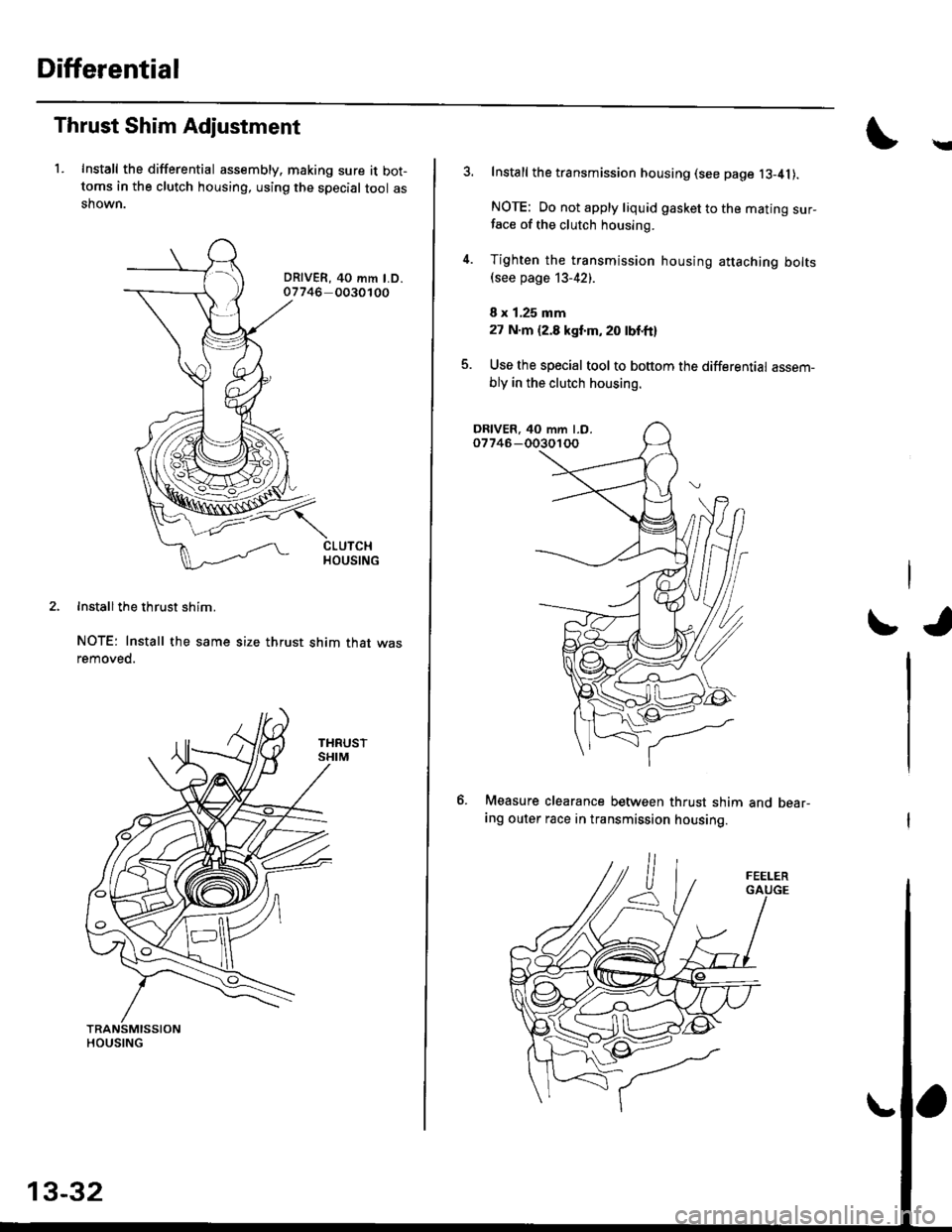
Thrust Shim Adjustment
1. Install the differential assembly, making sure it bot-toms in the clutch housing, using the special tool asshown.
DRIVER, 40 mm LD.07746 0030100
Install the thrust shim.
NOTE: Install the same size thrust shim that wasremoved.
Y
Install the transmission housing (see page l3-41).
NOTE: Do not apply liquid gasket to the mating sur-face of the clutch housing.
Tighten the transmission housing attaching bolts(see page 13-42).
I x 1,25 mm
27 N.m (2.8 kgt'm, 20 lbf'ft}
Use the special tool to bottom the differential assem-
bly in the clutch housing.
tJ
6. Measure clearance between thrust shim
ing outer race in transmission housing.
and bear-
13-32
Page 614 of 2189
Clutch Housing Bearing
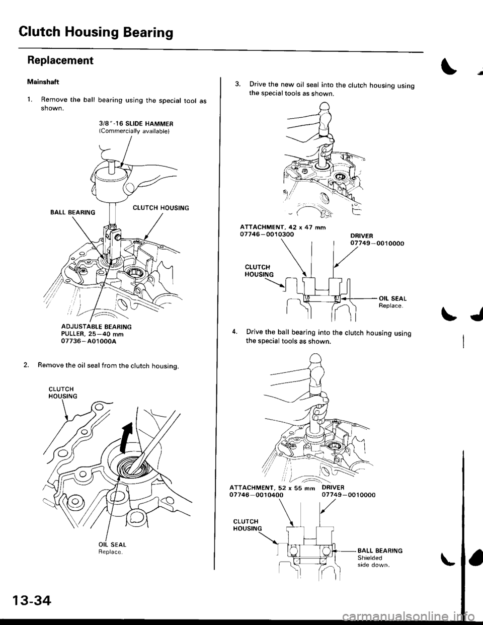
Replacement
Mainshaft
1. Remove the ball
shown.
bearing using the special tool as
3i8 " -16 SLIDE HAMMER(Commercially available)
ADJUSTAELE BEARINGPULLER, 25-40 mm07736-AO10004
2, Remove the oil seal from the clutch housing,
CLUTCH
Replace.
13-34
l.
3, Drive the new oil seal into the clutch housing usingthe specialtools as shown.
ATTACI{MENT, 42 x 47 mm07746 -0010300
CLUTCHHOUSING
Drive the ball bearing into the clutch housing usingthe special tools as shown.
ATTACHMENT, 52 x 55 mm DRIVER07746 001040007749-0010000
t./
07749 -0010000
Page 615 of 2189

PULLER, 25-40 mm07736-AO1000A
\
2. Install t")
Cou ntershaft
1. Remove the needle bearing using the special tool as
shown. then remove the oil guide plate
3/g " -16 SLIDE HAMMER
{Commercially available)
PULLER, 25-40 mm07736-AO1000A
\
2. Install the oil guide Plate, then
bearing into the clutch housing
tools as shown.
d rive the needle
using the special
'1: ATTACHMENT, 42 x 47 mm
07746-0010300*2: ATTACHMENT, 52 x 55 mm
07746 -0010400
ORIVER07749 -0010000
CLUTCHHOUSING
NEEOLE BEAFING
GUIDE PLATE
NEEOLE BEARING
*1: D16Y7 enqine*2: D16Y5, D16Y8 engines
OIL GUIDE PTATE
13-35
Page 616 of 2189
Mainshaft Thrust Shim
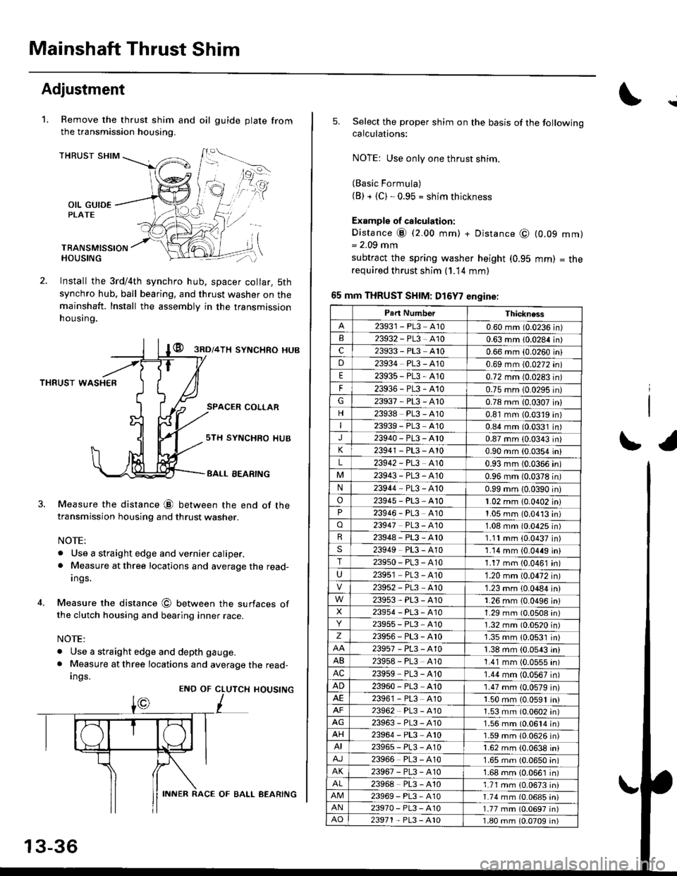
Adjustment
Remove the thrust shim and oil
the transmission housing.
1.gu ide plate from
THRUST SHIM
OIL GUIDEPLATE
TBANSMISSIONHOUSING
Install the 3rd/4th synchro hub, spacer collar, 5th
synchro hub, ball bearing, and thrust washer on themainshaft. Install the assembly in the transmission
h ousing.
@ gnol+lx syNcHRo HUB
THRUST WASHER
SPACER COLLAR
4.
Measure the distance @ between the end of thetransmission housing and thrust washer.
NOTE:
. Use a straight edge and vernier caliper.. Measure at three locations and average the read-
Ings.
Measure the distance @ between the surfaces ofthe clutch housing and bearing inner race.
NOTE:
. Use a straight edge and depth gauge.
. Measure at three locations and average the read-
Ings.
sTH SYNCHRO IIUB
BALL EEARING
CLUTCH
L
HOUSINGENO OF
13-36
INNER RACE OF BALL AEARING
\
5.Select the proper shim on the basis of the followingcalculations:
NOTE: Use only one thrust shim.
(Basic Formula)(B) + {C). 0.95 = shim thickness
Example of calculation:
Distance @ (2.00 mm) + Distance @= 2.09 mm
subtract the spring washer height (0.95
required thrust shim (1.14 mm)
65 mm THRUST SHIM: D16Y7 engine:
(0.09
mm)
mm)
= tne
r1
Part NumborThickness
23931 - PL3 A100.60 mm (0.0236 in)23932 - PL3 A100.63 mm 10.0284 in)c23933 - PL3 A100.66 mm {0.0260 iniD23934 PL3 - A100.69 mm (0.0272 in)
E23935-PL3-4100.72 mm 10.0283 in)
F23936-PL3-4100.75 mm 10.0295 in)G23937-PL3-A100.78 mm {0.0307 in}
23938 PL3 - A100.81 mm (0.0319 in)I23939 - PL3 At00.84 mm (0.0331 in)J23940-PL3-Ar00.87 mm (0.0343 in)
23941 - PL3 - A100.90 mm (0.0354 in)
L23942 - PL3 A100.93 mm (0.0366 in)
23943-PL3-A100.96 mm (0.0378 in)N23944 PL3 - A100.99 mm 10.0390 in)
o23945-PL3-A101.02 mm {0.0402 in}23946 - PL3 A101.05 mm (0.0413 in)o23947 PL3 - 4101.08 mm (0.0425 in)R23948-PL3-A101.11mm (0.0437 in)s23949 PL3 - A101.14 mm {0.0449 in}T23950-PL3-A101.17 mm (0.0461 in)
U23951 PL3 - A101.20 mm (0.0472 in)
23952-PL3-Ar01.23 mm {0.0484 in)
23953-PL3-A101.26 mm {0.0496 in}X23954 - P13, A101.29 mm (0.0508 in)23955 - PL3 A101.32 mm (0.0520 in)z23956-PL3-Ar01.35 mm {0.0531 in)
23957-PL3-A101.38 mm (0.0543 in)
AB239s8 - PL3 A101.41 mm (0.0555 in)AC23959 PL3 - A101.44 mm (0.0567 in)
AD23960 - PL3 A101.47 mm (0.0579 in)23961 - PL3 4101.50 mm (0.0591 in)23962 PL3 - A101.53 mm (0.0602 in)AG23963-PL3-4101.56 mm (0.0614 in)AH23964 - PL3 A101.59 mm (0.0626 in)AI23965-PL3-A101.62 mm {0.0638 in)
23966 PL3 - A101.65 mm (0.0650 in)AK23967-PL3-A101.68 mm {0.0661 in)
23968 PL3 - A101.71 mm {0.0673 in)23969-PL3-A101.74 mm (0.06a5 iniAN23970- PL3 -A101.77 mm (0.0697 in)AO23971 - PL3 - A101.80 mm 10.0709 in)
Page 626 of 2189
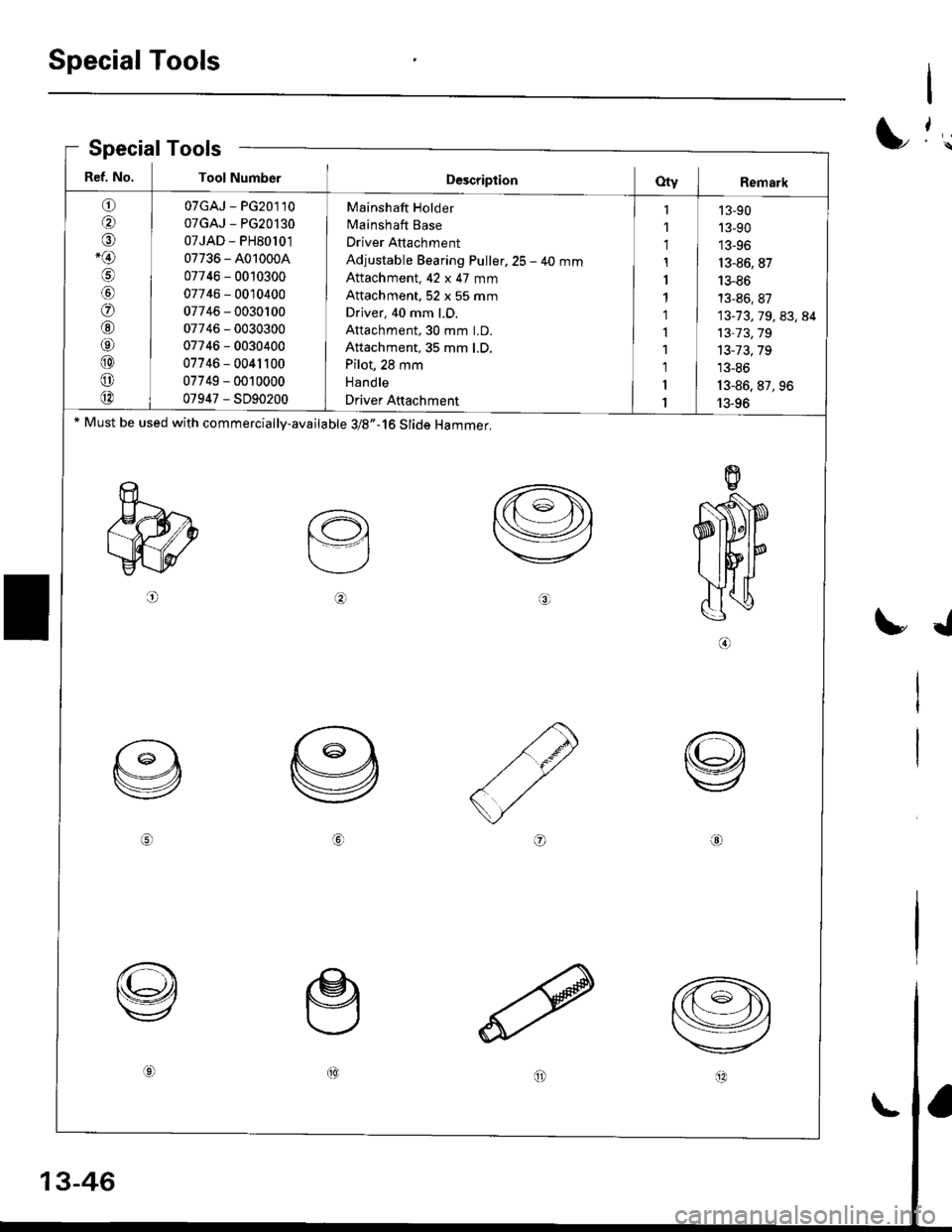
Special Tools
SpecialTools
I
I
I
./
Ref. No. Tool NumberD€scriptionOty I Remark
o
@
o-@
@
o
@
@
@
o
@
07GAJ - PG20110
07GAJ - PG20l30
07JAD - PH80l0'1
07736 - A010004
07746 - 0010300
07746 - 0010400
07746 - 0030100
07746 - 0030300
07746 - 0030400
07746 - 0041100
07749 - 0010000
07947 - SD90200
Mainshaft Holder
Mainshaft Base
Driver Attachment
Adjustable Bearing Puller,25 - 40 mm
Attachment, 42 x 47 mm
Attachment, 52 x 55 mm
Driver, 40 mm LD.
Attachment, 30 mm LD.
Attachment, 35 mm LD.
Pilot, 28 mm
Hand le
Driver Attachment
I
1
1
1
I
1'l
I
1
1
1'I
13-90
13-90
13-96
13-86, 87
13-86
13-86, 87
13-73,79,83,84
13-73,19
13-73,79
13-86
13-86,87,96
13-96* Must be used with commercially-available 3/8,,-16 Slide Hammer.
o
aol@(t4^
Page 652 of 2189
Mainshaft Assembly
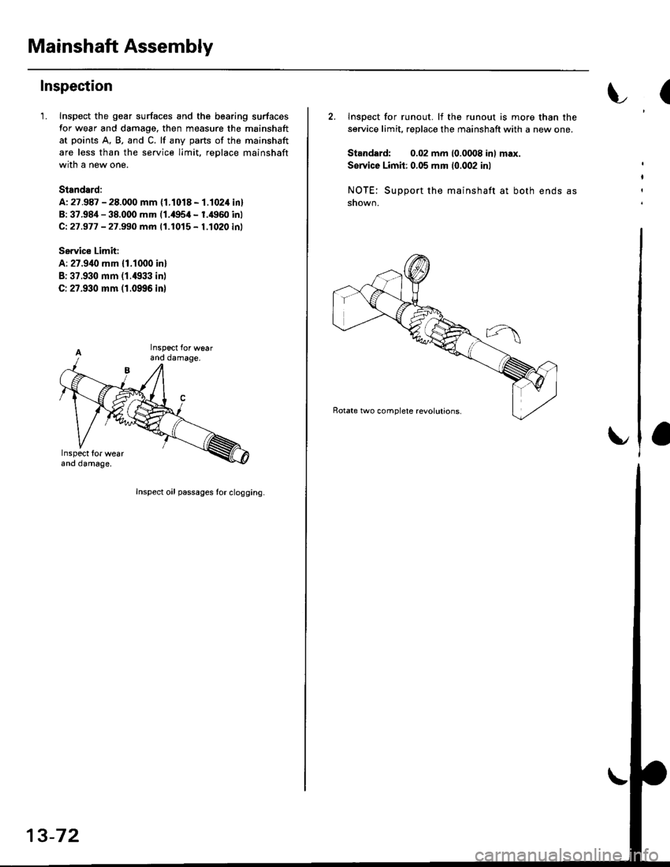
Inspection
1. Inspect the gear surfaces and the bearing surfaces
for wear and damage. then measure the mainshaft
at points A, B, and C. lf any parts of the mainshaft
are less than the service limit, reDlace mainshaft
with a new one.
Standard:
A: 27.987 - 28.000 mm {1.1018 - 1.1024 in}
B: 37.98i1 - 38.fi)0 mm (1.,|!t5,0 - 1.4960 inl
Ci27.977 - 27.990 mm 11.1015 - 1.1020 inl
Service Limit:
A; 27.940 mm {1.1000 in}
B: 37.930 mm (1./{133 in)
C:27.930 mm (1.0996 inl
(
2. Inspect for runout. lf the runout is more than the
service limit, replace the mainshaft with a new one,
Standard: 0.02 mm 10.0008 inl max.
Ssrvice Limit: 0.05 mm 10.002 inl
NOTE: Suooort the mainshaft at both ends as
shown.
t
Inspect for wearano oamage.
Inspect oil passages tor clogging.
13-72
Page 653 of 2189
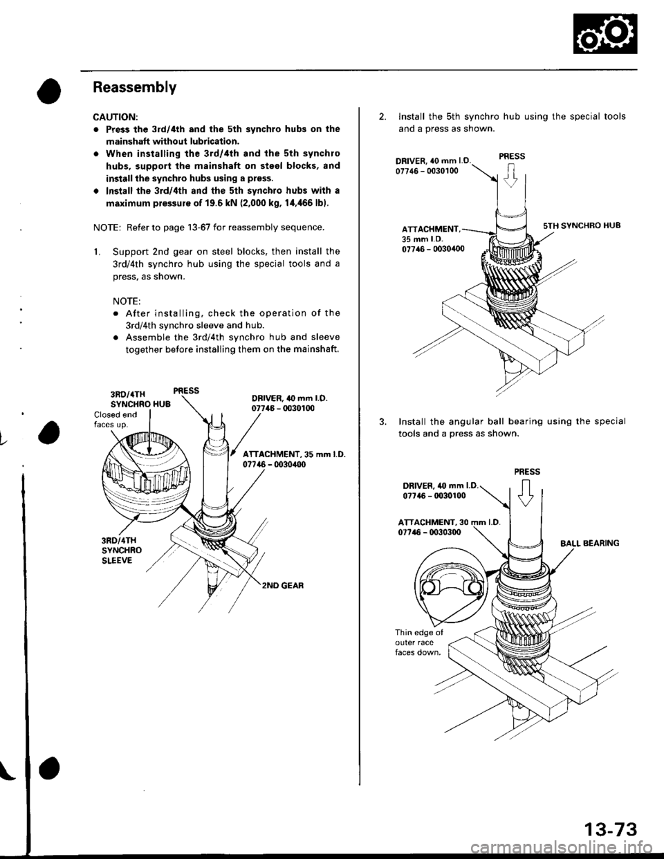
Reassembly
CAUTION:
. Press the 3rd/4th and the 5th synchro hubs on the
mainshaft without lubrication.
o When installing the 3rd/,lth and the sth synchro
hubs, support the mainshaft on steel blocks, and
installthe synchro hubs using a prsss.
. Install the 3rd/4th and the sth synchro hubs with a
maximum plessur€ of 19.6 kN (2,000 kg, 14,466 lbl.
NOTE: Refer to page 13-67 for reassembly sequence.
1, Support 2nd gear on steel blocks, then install the
3rd/4th synchro hub using the special tools and a
press, as snown.
NOTE:
. After installing. check the operation of the
3rd/4th synchro sleeve and hub.
. Assemble the 3rd/4th synchro hub and sleeve
together betore installing them on the mainshaft.
Closed end
3RD/4THSYNCHRO HU3DBIVER, 10 mm l.O.07746 - 00301U)
/ lrrlcHlileNr. ss .- t.o.07746 - 0030,100
l.
3RD/{THSYNCHROSLEEVE
2ND GEAR
2. Install the sth synchro hub using the special tools
and a press as snown.
DRIVER, {0 mm l.O.07746 - 0030100
ATTACHMENT,35 mm LD.
sTH SYNCHRO HUB
07716 - 0030,100
3. Install the angular ball bearing using the special
tools and a press as shown.
PRESS
+
DRIVER, 40 mm LD.0?7a6 - It030100
Page 659 of 2189
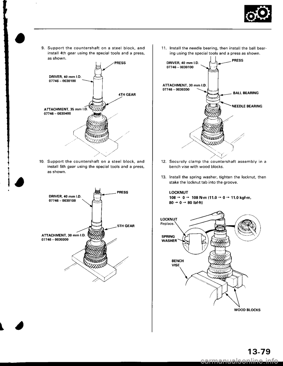
9. Support the countershaft on a steel block, and
install 4th gear using the special tools and a press.
as 5nown.
ATTACHMENT,35 mm LD.07746 - 0030400
Support the countershaft on a steel block, and
install 5th gear using the special tools and a press,
as shown.
ATTACHMENT, 30 mm I,D,07746 - 0030300
10.
\
'1'1. Install the needle bearing, then install the ball bear-
ing using the special tools and a press as shown.
PRESSDRIVER,40 mm LD.07746 - 0030100
ATTACHMENT,30 mm LD.07746 - 0030300
J.-12.Securely clamp the countershaft assembly in a
bench vise with wood blocks.
lnstall the spring washer, tighten the locknut, then
stake the locknut tab into the groove.
LOCKNUT
108- 0- 108N.m 111.0- 0- 11.0kgt.m,
80+ 0* 80 lbf'ftl
WOOD BLOCKS
13-79
Page 664 of 2189
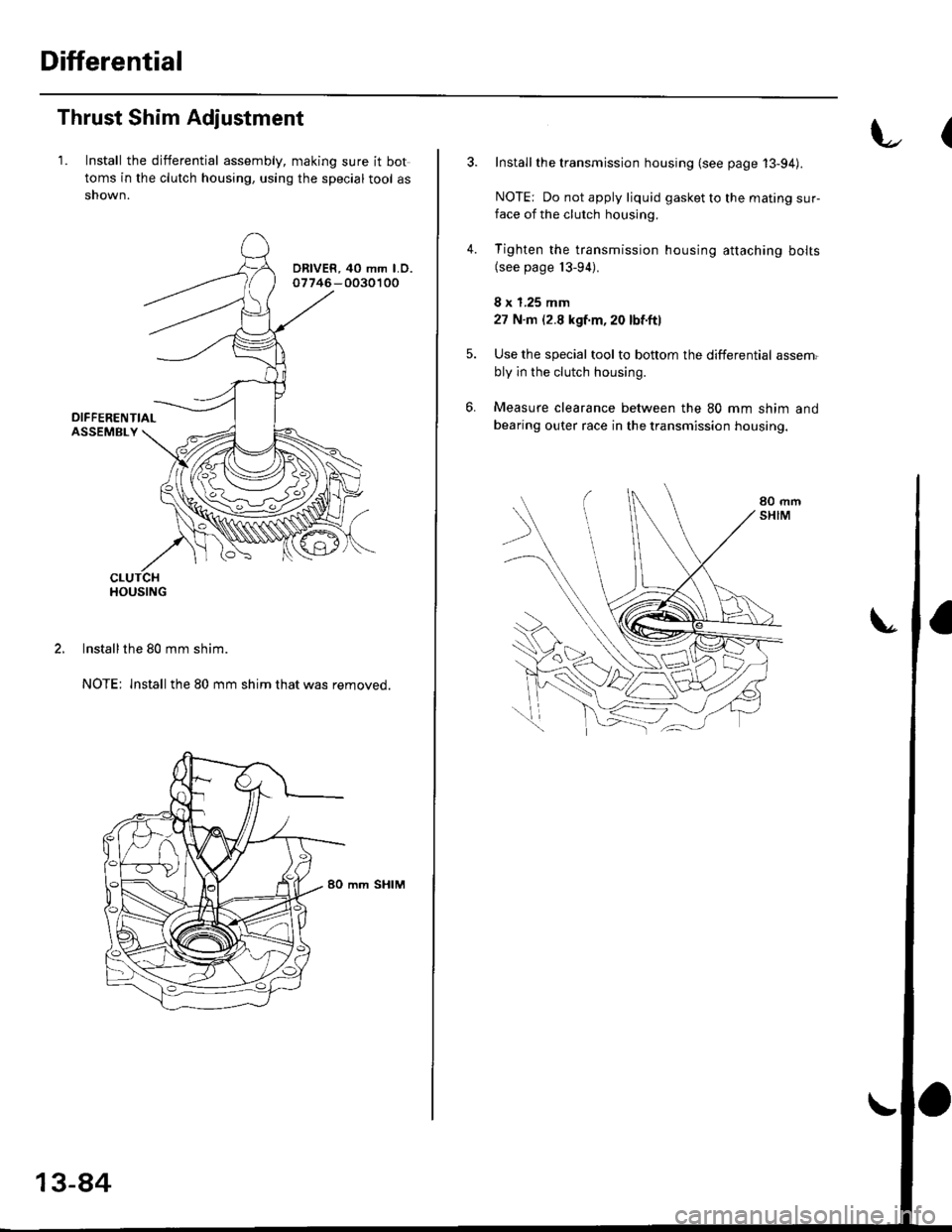
Differential
Thrust Shim Adjustment
1. Install the differential assembly, making sure it bot
toms in the clutch housing, using the special tool as
shown.
ORIVER, 40 mm LO.o7746-0030100
lnstall the 80 mm shim.
NOTE: lnstall the 80 mm shim that was removed.
mm SHIM
13-84
(
4.
Install the transmission housing (see page 13-94).
NOTE: Do not apply liquid gasket to the mating sur-
face of the clutch housing.
Tighten the transmission housing attaching bolts(see page 13-94).
I x 1.25 mm
27 N'm (2.8 kgf.m, 20 lbf.ftl
Use the special tool to bottom the differential assem.
bly in the clutch housing.
Measure clearance between the 80 mm shim and
bearing outer race in the transmission housing.