lock HONDA CIVIC 2002 7.G Owners Manual
[x] Cancel search | Manufacturer: HONDA, Model Year: 2002, Model line: CIVIC, Model: HONDA CIVIC 2002 7.GPages: 1139, PDF Size: 28.19 MB
Page 424 of 1139
Manual Transmission
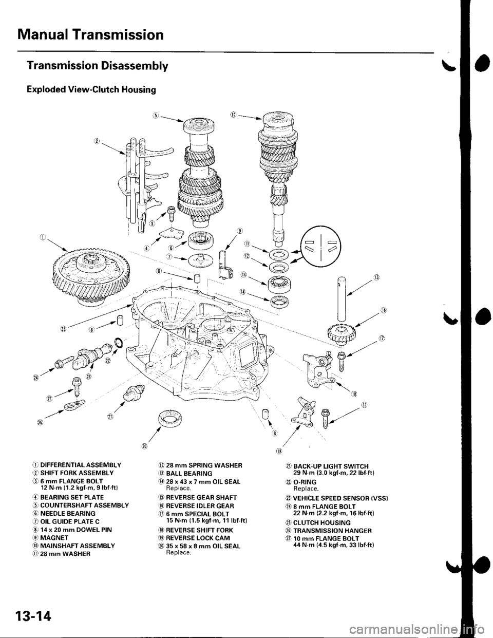
Transmission Disassembly
Exploded View-Clutch Housing
,.Y
-'- R
,ot/u
,t- v -1A' i6 t3l
\?
q'/V^
.!) DIFFERENTTAL ASSEMBLY
r2l SHIFT FORK ASSEMBLY
a9l 6 mm FLANGE BOLT12 N.m (1.2 kgf m,9lbf ftl
..4] BEARING sET PLATE
G, COUNTERSHAFT ASSEMBLY
O NEEDLE BEARING
3 OIL GUIDE PLATE C
e 14 x 20 mm DOWEL PIN
.9-i MAGNETi.!! MAINSHAFT ASSEMBLY
U 28 mm WASHER
t€4
i[, 28 mm SPRING WASHERiO BALL BEARING(l 28 x 43 x 7 mm OIL SEALReplace.
.D REVERSE GEAR SHAFT
1' REVERSE IDLER GEARf lr 6 mm SPECIAL BOLT15 N.m (1.5 kgt.m, 11 lbf.ft)
(!I REVERSE SHIFT FORK
.4' REVERSE LOCK CAMQ-t 35 x 58 x 8 mm OIL SEALReplace.
n""
?]] BACK-UP LIGHT SWITCH29 N m (3.0 kgf.m,22 lbf ftl.?1 O.RINGReplace.
1!) VEHICLE SPEEo sENsoR (Vss).O 8 mm FLANGE BOLT22 N.m (2.2 kgf m, 16lbf.ftl
.' CLUTCH HOUSINGiI6) TRANSMISSION HANGER
tl 10 mm FLANGE BOLT44 N.m {4.5 kgt.m,33 lbf.ft}
:
r'<__J'.@t / ,, tl
' j=-X ri ,1.-6
'-==-Yh,_-9
13-14
Page 425 of 1139
o,. @\
'\b
e
P\B
z-W
-
€:
iq { "
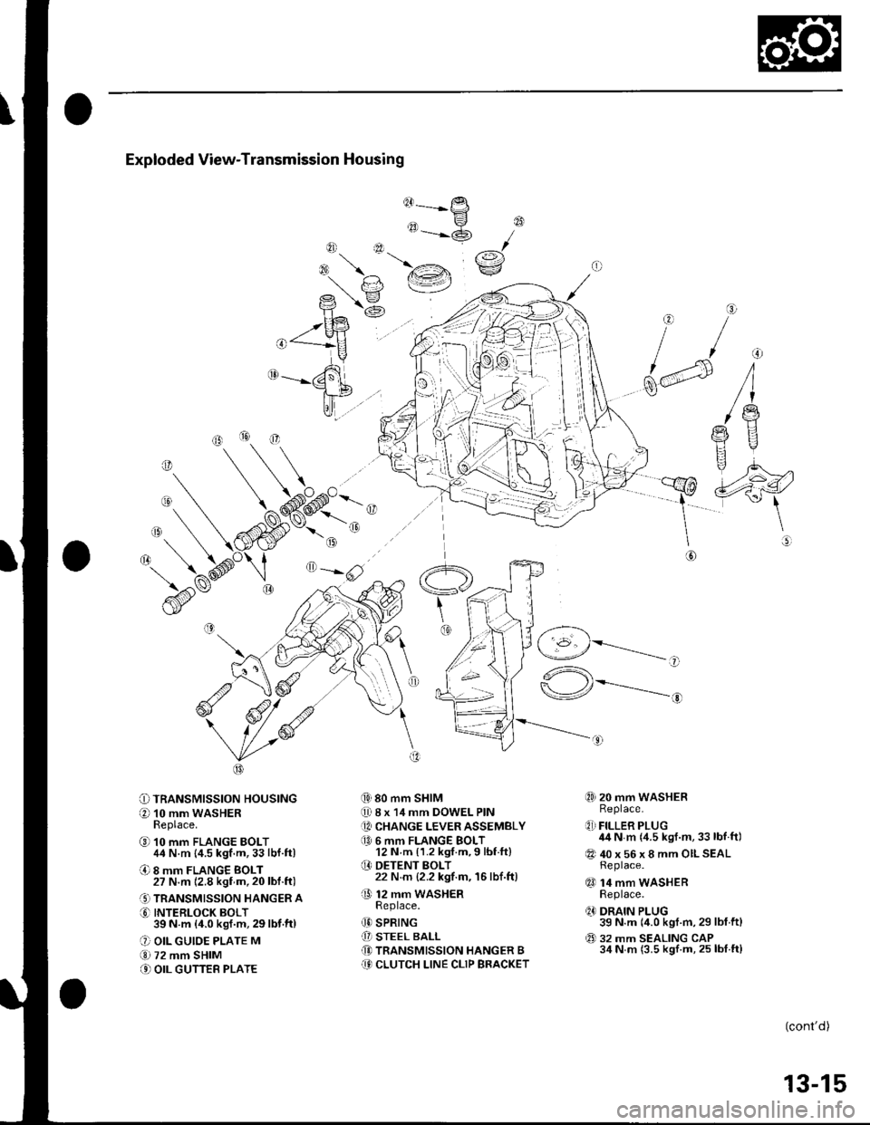
Exploded View-Transmission Housing
@------
tt-P
"=-@
{i) 80 mm SHIM
0 8 x 14 mm DOWEL PIN
[A CHANGE LEVER ASSEMBLY
a0 6 mm FLANGE BOLT12 N m {1.2 kgf.m,9 lbf ft}
O DETENT BOLT22 N.m {2.2 kgf.m, 16lbf.ft)
O 12 mm waSHERReDlace.
(D SPRING
[I STEEL BALL(D TRANSMISSION HANGER B(9 CLUTCH LINE CLIP BRACKET
@
rai\€:/
o
f/
dd
\@
O=-rlF,z
O TRANSMISSION HOUSING
O 10 mm WASHERReplace.
@ 10 mm FLANGE BOLT44 N.m {4.5 kgf.m,33lbf.ft)
O 8 mm FLANGE BOLT27 N.m 12.8 kgf m,20lbl.ft)
.' TRANSMISSION HANGER A
O INTERLOCK BOLT39N m (4.0ksf.m,29lbf.ft)
O OIL GUIOE PLATE M
€.1 72 mm SHIM
.' OIL GUTTEB PLATE
,-1 _\(g/----------__-
"^\
\-/r*---------..-,
@) 20 mm WASHERReplace.
q,] FILLER PLUG44 N m {4.5 kgf.m,33 lbf.ft)
@ 40 x 56 x 8 mm OILSEALReplace.
qO 14 mm WASHERReplace.
q' DRAIN PLUG39 N.m (4.0 kgf.m,29 lbf.ftl
@ 32 mm SEALING CAP34 N m (3.5 kgf.m, 25 lbf.ft)
o
(cont'd)
13-15
Page 426 of 1139
Manual Transmission
Transmission Disassembly (cont'd)
NOTE: Place the clutch housing on two pieces of wood
thick enough to keep the mainshaft from hitting the
workbench.
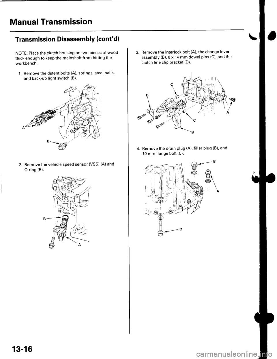
1. Remove the detent bolts (A), springs, steel balls,
and back-up light switch (B).
Remove the vehicle speed sensor (VSS) (A) and
O-ring (B).
13-16
3, Remove the interlock bolt (A), the change lever
assembly (B), 8 x 14 mm dowel pins (C), andthe
clutch line clip bracket {D).
€
Remove the drain plug (A), filler plug (B), and
10 mm flange bolt (C).
Page 427 of 1139
6.
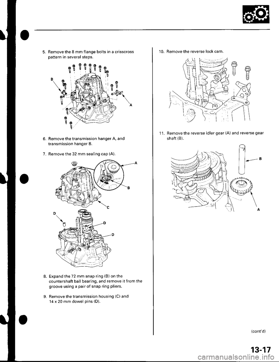
5. Remove the 8 mm flange bolts in a crisscross
Dattern in several steos.
Remove the transmission hanger A, and
transmission hanger B.
Remove the 32 mm sealing cap (A).
Expand the 72 mm snap ring (B) on the
countershaft ball bearing, and remove it from the
groove using a pair of snap ring pliers.
Remove the transmission housing (C) and
14 x 20 mm dowel pins (D).
7.
L
10. Remove the reverse lock cam.
g
t.l Y
g
11.Remove the reverse idler gear {A) and reverse gear
shaft {B).
(,
^A
(cont'd)
13-17
Page 430 of 1139
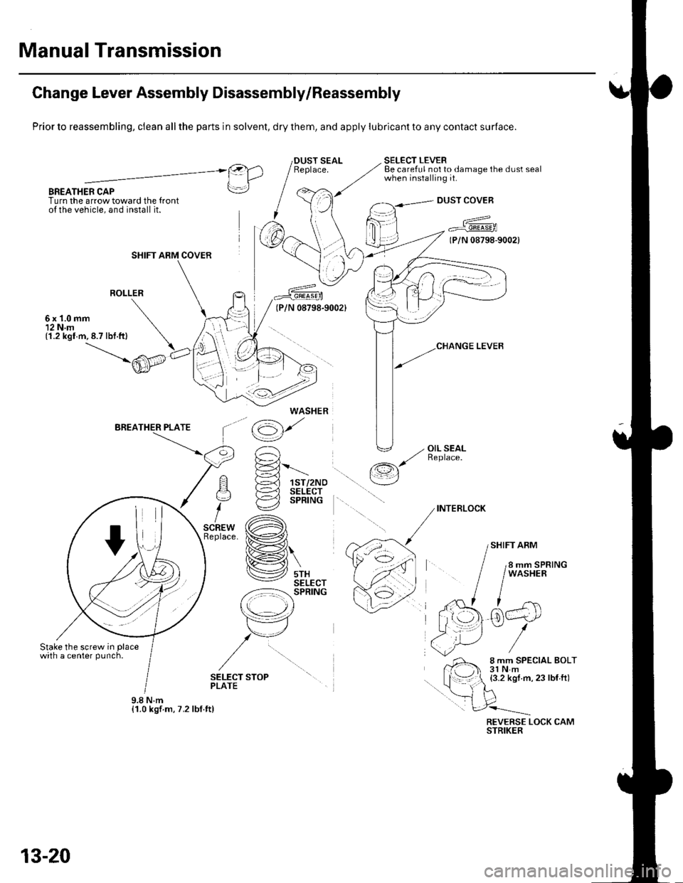
Manual Transmission
Change Lever Assembly Disassembly/Reassembly
Prior to reassembling, clean all the parts in solvent, dry them, and apply lubricant to any contact surface.
BREATHER CAPTurn the arrow toward the {ronto{ the vehicle, and install it.
SELECT LEVERBe careful not to damage the dust sealwhen installing it.@).1 IlLrl
rrl
I
DUST COVEB
a^^
7 Fr"irr6-rooa
(P/N 08798-9002)
ROLLER
6x1.0mm12 N.m(1.2 kgl.m,8.7 lbf.ft)
'^ E-='-Fl !-d 1sr/2Noq )-=^l sELEcr
i €2 sPntruc
,.* (A)tace. ix�#,,l
H\
lV srxSELECT-z:-=:l-': SPRING
r\
tr7
,/u
/
\op
(g)'
' -, OIL SEAL,/ ReDlace./-r,s
\__/
INTERLOCK
SHIFT ARM
SELECT STOPPLATE
REVERSE LOCK CAMSTRIKER
SHIFT ARM COVER
WASHER
9.8Nm{1.0 kgf.m, 7.2 lbf.ft)
13-20
Page 435 of 1139
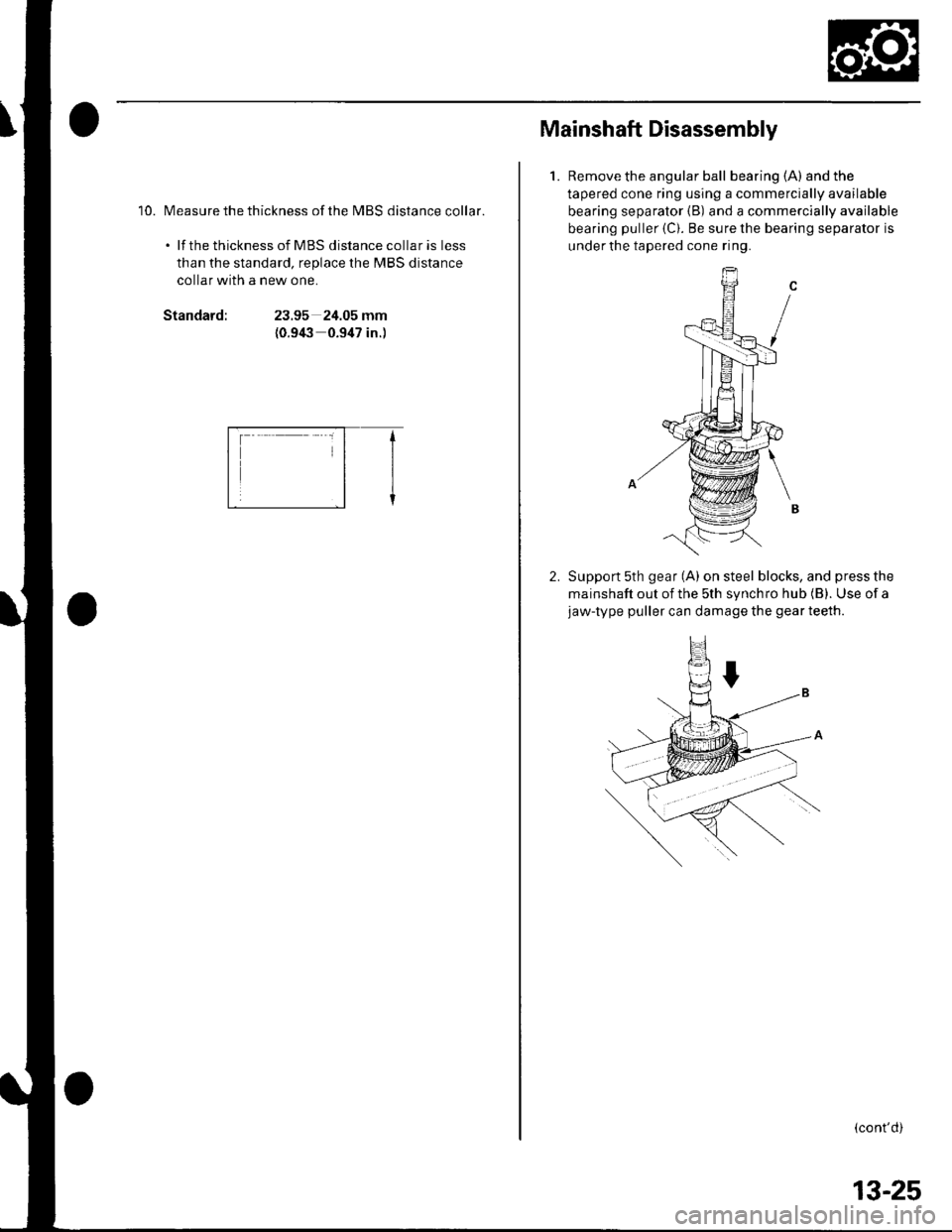
'10. Measure the thickness ofthe MBS distance collar.
. lf the thickness of MBS distance collar is less
than the standard, replace the MBS distance
collar with a new one.
Standard:23.95 24.05 mm
{0.9(3 0.947 in.)
E-f
Mainshaft Disassembly
1.Remove the angular ball bearing (A) and the
tapered cone ring using a commercially available
bearing separator {B) and a commercially available
bearing puller {C). Be sure the bearing separator is
under the tapered cone ring.
Support 5th gear (A) on steel blocks, and press the
mainshaft out of the sth synchro hub (B). Use of ajaw-type puller can damage the gear teeth.
(cont'd)
13-25
Page 436 of 1139
Manual Transmission
Mainshaft Disassembly (cont'dl
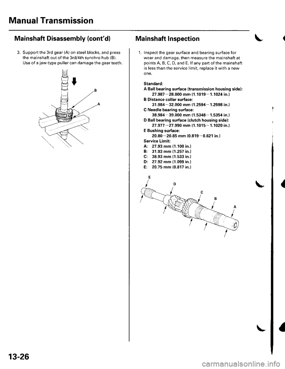
3. Supportthe 3rd gear (A) on steel blocks, and press
the mainshaft out of the 3rd/4th synchro hub (B).
Use of a jaw-type puller can damage the gear teeth.
13-26
Mainshaft Inspection
1. Inspect the gear surface and bearing surface for
wear and damage, then measure the mainshaft at
points A, B, C, D, and E. lf any part of the mainshaft
is less than the service limit, reDlace it with a new
o ne.
Standard:
A Ball bearing surface (transmission housing side):
27.987 28.000 mm (1.1019 1.1024in.)
B Distance collar surtace:
31.984 32.000 mm {1.2594 1.2598in.)
C Needle bearing surlace:
38.984-39.000 mm (1.53/t8 1.5354 in.)
D Ball bearing surface (clutch housing side):
27 .977 -27 .990 mm (1.1015 1.1020in.)
E Bushing surface:
20.80 20.85 mm (0.819 0.821 in.)
Service Limit;
A: 27.93 mm 11.100 in.l
B: 31.93 mm |.1.257 in.l
C: 38.93 mm 11.533 in.l
Di 27.92 mm {1.099 in.l
E: 20.75 mm 10.817 in.l
{
Page 442 of 1139
Manual Transmission
Countershaft Assembly Clearance
Inspection (cont'd)
5. Measure the th ickness of the distance collar.
. lf thethickness is notwithin the standard, replace
the distance collar with a new one.. lf thethickness iswithinthe standard, goto
step 6.
Standard: 28.03 28.08 mm {1.104-1.106 in.)
6. Measure the thickness of the 2nd qear.
. lf thethickness of 2nd gearis lessthan the
service limit, replace 2nd gear with a new one.. lf thethicknessof 2nd geariswithintheservice
limit, replace lhe 1sV2nd synchro hub with a new
one.
Standard: 27 -92-21.97 mm|.1.099 1.r01 in.l
Service Limit: 27.87 mm 11.097 in.)
13-32
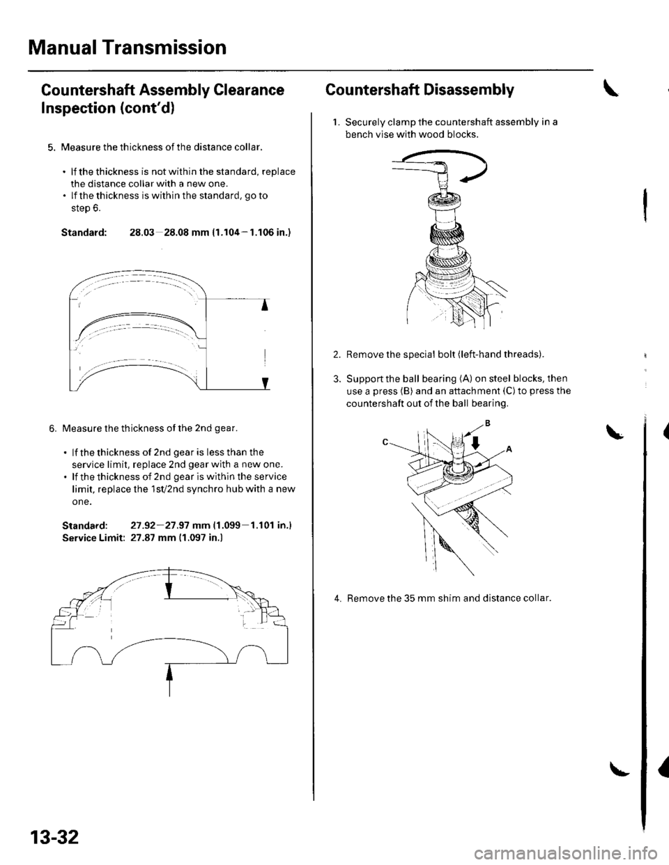
Countershaft Disassembly
1.Securely clamp the countershaft assembly in a
bench vlse with wood blocks.
Remove the special bolt (left-hand threads).
Support the ball bearing (A) on steel blocks, then
use a press (B) and an attachment (C)to press the
countershaft out of the ball bearing.
4. Remove the 35 mm shim and distance collar.
I
Page 443 of 1139
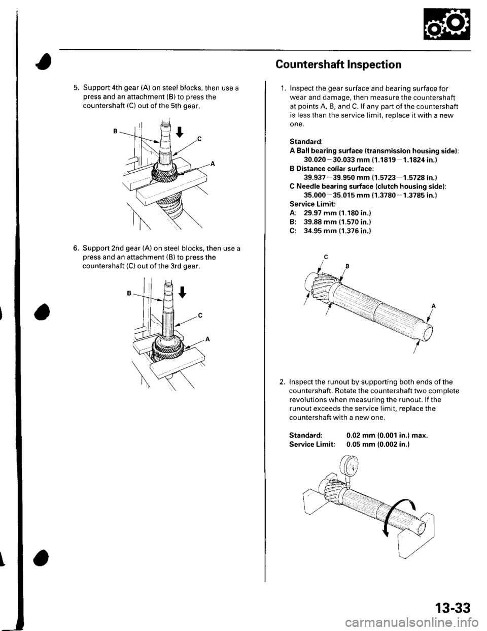
5. Support 4th gear (A) on steel blocks, then use apress and an attachment (B) to press the
countershaft (C) out ofthe 5th gear.
6.Support 2nd gear (A) on steel blocks, then use a
Dress and an attachment {B} to press the
countershaft (C) out of the 3rd gear.
Cou ntershaft lnspection
1. Inspect the gear surface and bearing surface for
wear and damage, then measure the countershaft
at points A, B, and C. lf any part of the countershaft
is less than the service limit, replace it with a new
one.
Standard:
A Ballbearing surface ltransmission housing sidel:
30.020 -30.033 mm {1.1819 1.1824in.)
B Distance collar surface;
39.937- 39.950 mm 11.5723 1.572A in.l
C Needle bearing surface (clutch housing side):
35.000 35.015 mm {r.3780-1.3785 in.)
Service Limit:
A: 29.97 mm {1.180 in.)
B: 39.88 mm {1.570 in.l
C: 34.95 mm {1.376 in.)
lnspect the runout by supporting both ends of lhe
countershaft. Rotate the countershaft two complete
revolutions when measuring the runout. lf the
runout exceeds the service Iimit, replace the
countershaft with a new one.
Standard: 0.02 mm (0.001 in.) max.
Service Limit: 0.05 mm (0.002 in.)
2.
13-33
Page 446 of 1139
Manual Transmission
10.
Countershaft Reassembly (cont'dl
9.Install the needle bearing.
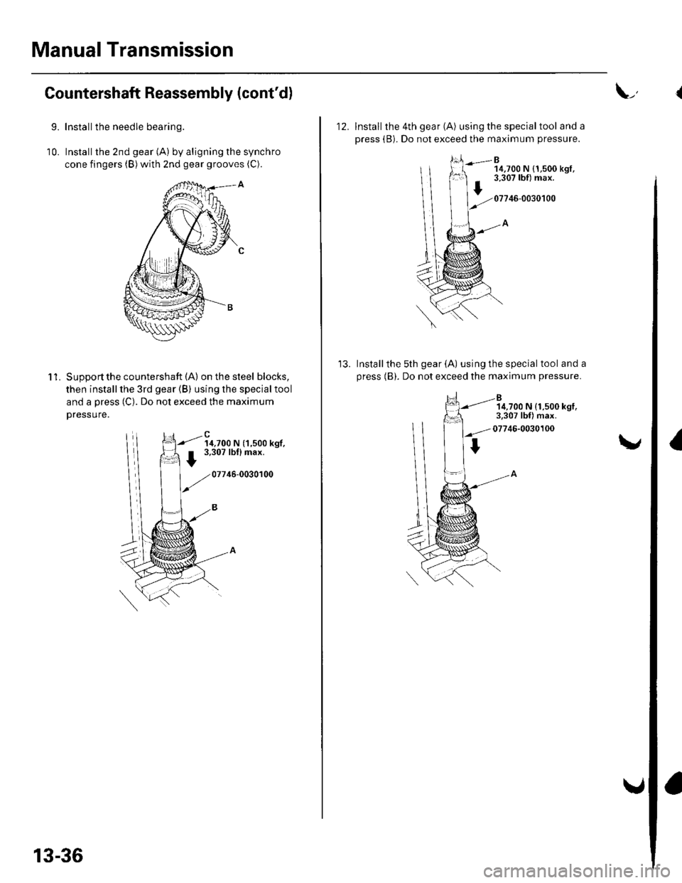
Installthe 2nd gear (A) by aligning the synchro
cone fingers (B) with znd gear grooves (C).
'l 1.Supoort the countershaft (A) on the steel blocks,
then install the 3rd gear (B) using the special tool
and a press (C). Do not exceed the maximum
Dressure.
14,700 N (1,500 kgf,3,307 lbflmax.
07746-0030100
13-36
L,
12. Install the 4th gear (A) using the specialtool and a
press (B). Do not exceed the maximum pressure.
B14,700 N {1,500 kgt,3,307 lbf) max.
07746-0030100
Installthe 5th gear (A) using the special tool and a
press (B). Do not exceed the maximum pressure.
14,700 N (1.500 kgl,3.307 lbf) max.
07746-0030100
I