lock HONDA CIVIC 2002 7.G Repair Manual
[x] Cancel search | Manufacturer: HONDA, Model Year: 2002, Model line: CIVIC, Model: HONDA CIVIC 2002 7.GPages: 1139, PDF Size: 28.19 MB
Page 166 of 1139
Engine Block
Oil Pan Installation (cont'dl
6. lf the engine is still in the vehicle, install the
subframe,
-1 Installthe subframe. Align the reference lines
on the subframe with the bolt head center, then
tighten the bolts (see step 5 on page 5-10).-2 Tighten the front mounting bolt (see step 6 onpage 5-10).-3 Tighten the rear mount mounting bolts (see
step 7 on page 5-11).-4 Connect the suspension lower arm ball joints
(see step 6 on page 18-19).
7. After assembly, wait at least 30 minutes before
filling the engine with oil.
7-28
v
Transmission End Grankshaft Seal
Installation - In Car
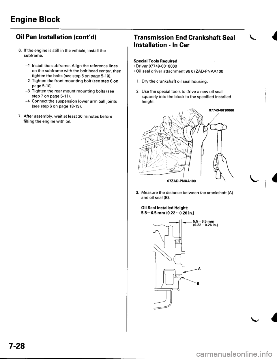
Special Tools Required. Driver 07749-0010000. Oil seal driver attach ment 96 07ZAD-PNAA100
'1. Dry the crankshaft oil seal housing.
2. Use the special tools to drive a new oil seal
squarely into the block to the specified installed
height.
07749-0010000
and oil seal (B).
Oil Seal Installed Height:
5.5 6.5 mm 10.22-0.26 in.l
5.5 6.5 mml0.22- O.26 in .l
I
/$rRfr4T
tr*W(r
-]t
fl\OTZAD.PNAAlOO
Measure the distance between the crankshaft (A)
a
Page 172 of 1139
Engine Lubrication
Engine Oil Filter Replacement
Special Tool Fequired
Oil filter wrench 07HAA-PJ70100
Engine Oil Filter (3/4-turn type)
1. Remove the oil filterwiththesDecial tool.
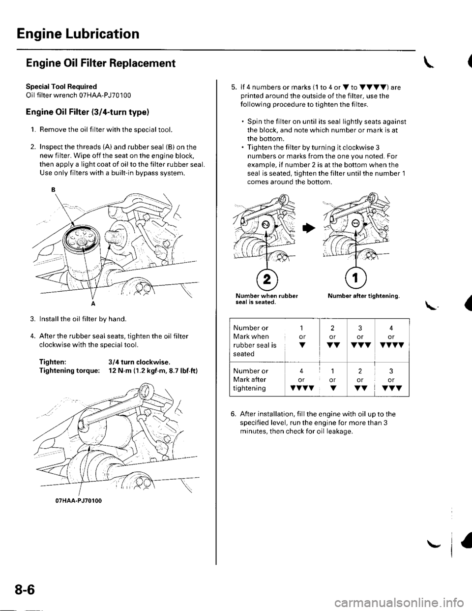
2. Inspect the threads {A) and rubber seal (B) on the
new filter. Wipe off the seat on the engine block,
then apply a light coat of oil to the filter rubber seal.
Use only filters with a built-in bypass system.
Installthe oilfilter by hand.
After the rubber seal seats, tighten the oil filter
clockwise with the special tool.
Tighten: 3/4 turn clockwise.
Tightening torque: 12 N.m (r.2 kgf.m,8.7 lbf.ft)
07HAA-PJ70100
8-6
\,
5. lf 4 numbers or marks (1 to 4 or V to VVVV) are
printed around the outside of the filter, use the
following procedure to tighten the filter.
. Spin the filter on until its seal lightly seats against
the block, and note which number or mark is at
the bottom.. Tighten the filter by turning it clockwise 3
numbers or marks from the one you noted. For
example, if number 2 is at the bottom when the
seal is seated, tighten the filter until the number 1
comes around the bottom.
Number when rubberseal is seated.Number after tightening.
(\..
6. After installation, fill the enginewith oil uptothe
specified level, run the engine for more than 3
minutes, then check for oil leakage.
Number or
Mark when
rubber seal is
1
or
V
2
or
VV
3
or
VVV
4
or
VVVV
Number or
Mark after
tightening
41
or or
vvvv. v
2
or
VV
3
or
VVV
Page 173 of 1139
Oil Filter Feed Pipe Replacement
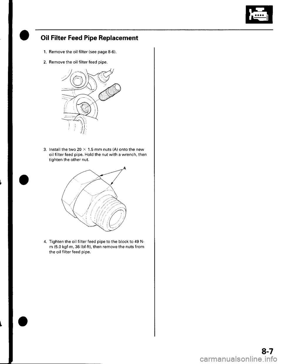
1.Remove the oilfilter (see page 8-6).
Remove the oil filter feed pipe.
3. lnstallthetwo20 x 1.5mmnuts(A) ontothenew
oil filter feed pipe. Hold the nut with a wrench, then
tighten the other nut.
4. Tightenthe oil filterfeed pipetothe blockto 49 N.
m {5.0 kgf.m, 36 lbf ft), then remove the nuts from
the oil filter feed oiDe.
8-7
Page 185 of 1139
Removal:
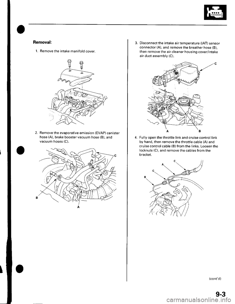
'1. Remove the intake manifold cover.
2.Remove the evaporative emission (EVAP) canister
hose (A), brake booster vacuum hose (B), and
vacuum hoses {C).
3. Disconnectthe intake airtemperature (lAT) sensor
connector (A), and remove the breather hose (B),
then remove the air cleaner housing cover/intake
air duct assembly (C).
4.Fully open the throttle link and cruise control link
by hand, then remove the throttle cable (A) and
cruise control cable (B) from the links. Loosen the
locknuts {C). and remove the cables from the
bracket.
(cont'd)
(
9-3
Page 189 of 1139
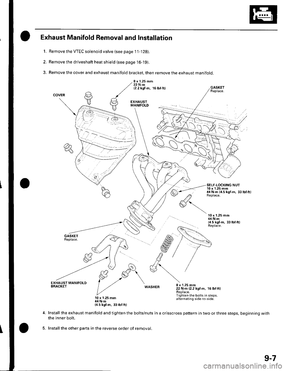
1.
2.
3.
Exhaust Manifold Removal and Installation
Remove the VTEC solenoid valve (see page 1 '1-128).
Remove the driveshaft heat shield (see page 16-19).
Remove the cover and exhaust manifold bracket, then remove the exhaust manifold.
8x 1.25 mm22 N.m(2.2 kgf.m, 16lbt.ftl
#'-.-
GASKETReplace.
SELF-LOCKING NUT10 x 1.25 mm44 N.m {4.5 ksf.m, 33lbt.ftlBeplace.
10 x 1.25 mm44 N.m(4.5 kgt.m, 33 lbl ftlReplace.
WASHEB8 x 1-25 mm22 N.m (2.2 kgI m, 16lbf.ft)Replace.Tighten the bolts in steps,alternating side to side.10 x 1.25 mm14 N.m{4.5 kgl.rn, 33lbf.ft)
5.
Install the exhaust manifold and tighten the bolts/nuts in a crisscross pattern in two or three steps, beginning withthe inner bolt.
Installthe other parts in the reverse order of removal.
9-7
Page 190 of 1139
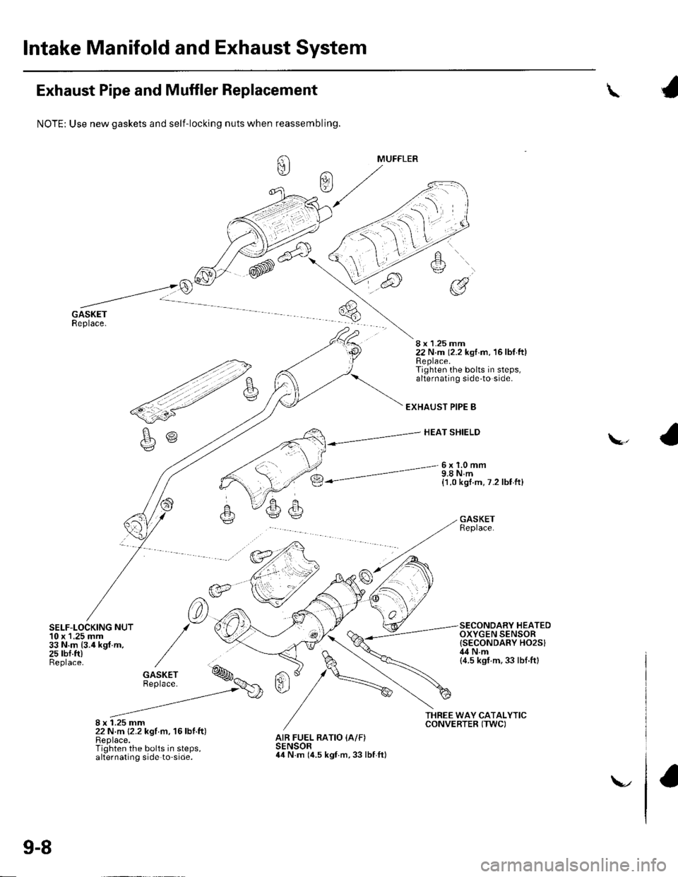
lntake Manifold and Exhaust System
Exhaust Pipe and Muffler Replacement
SELF-LOCKING NUT10 x 1.25 mm33 N.m {3.4 kgf.m,25 rbf.ft)Beplace.
8 x 1.25 mm22 N.m {2.2 kgf m, 16lbf.ft)Replace.Tighten the bolts in steps,alternating side to-side.
\
NOTE: Use new gaskets and self-locking nuts when reassembling.
8 x 1.25 mm22 N.m (2.2 kst.m. 16lbf.ftlReplace.Tighten the bolts in steps,alternating side'to side.
EXHAUST PIPE B
HEAT SHIELD\,
6x1.0mm9.8 N.m{1.0 kgt.m, 7.2 lbf ft}
GASKETReplace.
SECONDARY HEATEDOXYGEN SENSOR{SECONDARY HO2SIil4Nm(4.5 ksf.m,33 lbf.ftl
AIR FUEL RATIO {A/F)SENSOR44 N.m (it.s kgf.m, 33 lbf ftl
9-8
\-.
Page 195 of 1139
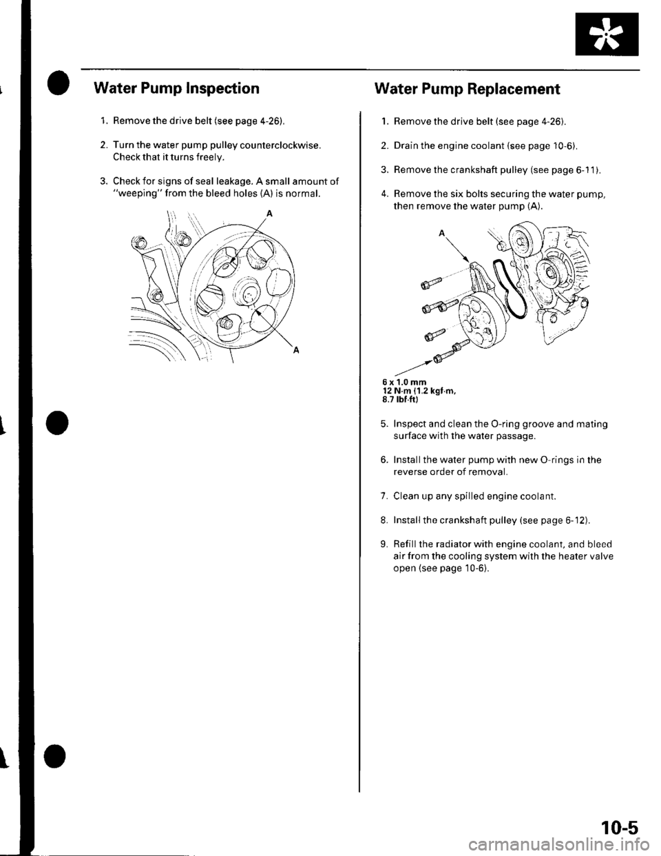
1.
2.
Water Pump Inspection
Remove the drive belt (see page 4-26),
Turn the water pump pulley counterclockwise.
Check that it turns freely.
Check for signs of seal leakage. A small amount of"weeping" from the bleed holes (A) is normal.
Water Pump Replacement
1. Remove the drive belt (see page 4-26).
2. Drain the engine coolant {see page 10-6).
3. Remove the crankshaft pulley (see page 6-11).
4. Remove the six bolts securing the water pump,
then remove the water pump (A).
6x1.0mm12 N m {1.2 kgt m,8.7 rbf.ft)
Inspect and clean the O-ring groove and mating
surface with the water passage.
Installthe water pump with new O rings in the
reverse order of removal.
7. Clean up any spilled engine coolant.
8. Installthe crankshaft pulley (see page 6-12).
L Refill the radiator with engine coolant, and bleed
air from the cooling system with the heater valve
open {see page 10-6}.
10-5
Page 199 of 1139
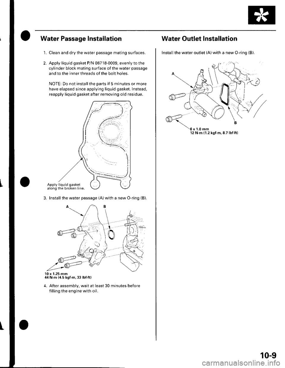
Water Passage Installation
1.Clean and dry the water passage mating surfaces.
Apply liquid gasket P/N 08718-0009, evenly to the
cylinder block mating surface ofthewater passage
and to the inner threads of the bolt holes.
NOTE: Do not installthe parts if 5 minutes or more
have elapsed since applying liquid gasket. Instead,
reapply liquid gasket after removing old residue.
3. Installthe water passage (A)with a new O-ring (B).
10 x 1.25 mm44 N m {4.5 kgt m.33 lbf.ft}
4. After assembly, wait at least 30 minutes before
filling the engine with oil.
.t':.:
Water Outlet lnstallation
Installthe water outlet (A)with a new O-ring {B),
12 N m (1.2 kgt m,8,7lbf ft)
10-9
Page 217 of 1139
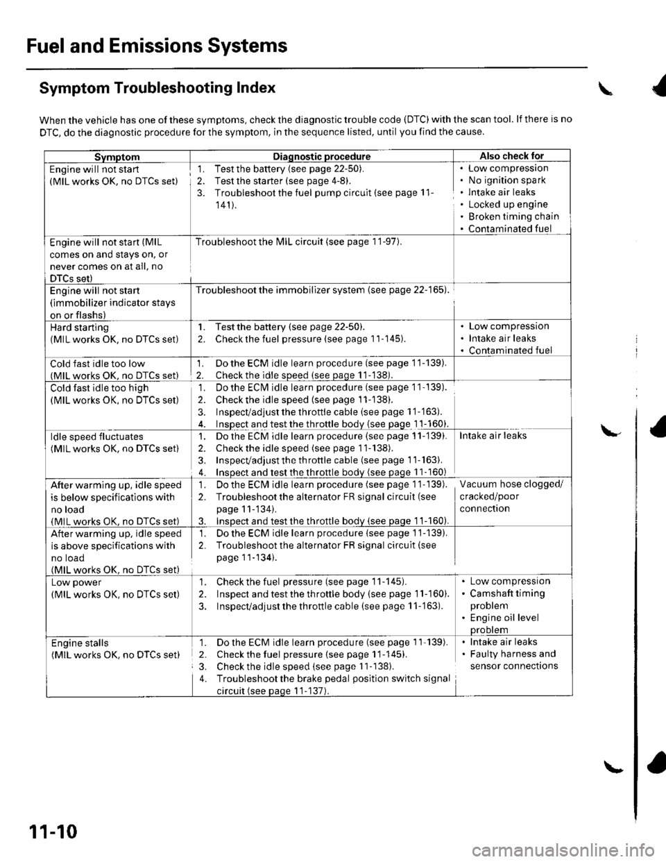
Fuel and Emissions Systems
Symptom Troubleshooting Index
When the vehicle has one of these symptoms, check the diagnostic trouble code (DTC) with the scan tool. lf there is no
DTC, do the diagnostic procedure for the symptom, in the sequence listed, until you find the cause.
SvmotomDiaqnostic procedureAlso check lor
Engine will not sta rt
(MlL works OK, no DTCS set)
1. Test the battery {see page 22-50).
2. Test the starter (see page 4-8).
3. Troubleshoot the fuel pump circult (see page 11
141).
Low compressron
No ignition spark
lntake air leaks
Locked up engine
Broken timing chain
Contaminated fuel
Engine will not start (MlL
comes on and stays on, or
never comes on at all, no
DTCS set)
Troubleshoot the l\4lL circuit (see page 1 '1-97).
Engine will not start
(immobilizer indicator stays
on or flashs)
Troubleshoot the immobilizer system (see page 22-165).
Hard starting(MlL works OK, no DTCS set)
1. Testthe battery (see page 22-50).
2. Checkthe fuel pressure (see page 11-145).
Low compression
Intake air leaks
Contaminated fuel
Cold fast idle too low(MlL works OK. no DTCS set)
1. Do the ECM idle learn procedure (see page 11-139).
2. Checkthe idle sDeed (see paqe 11-138).
Cold fast idle too high
(MlL works OK, no DTCS set)
Do the ECI\4 idle learn procedure (see page 1 1- 139).
Checkthe idle speed {see page 11-138).
Inspect/adjust the throttle cable (see page 1 '1-'163).
Inspect and test the throttle body {see page 1 1-160}.
']�
2.
3.
ldle speed fluctuates
(MlL works OK, no DTCS set)
1. Dothe ECM idle learn procedure (see page 11-'139).
2. Check the idle speed (see page 11-138).
3, Inspecvadjust th e throttle cable (see page 11''163).
4. Insoect and test the throttle bodv (see paqe 11- 160)
Intake air leaks
After warming up, idle speed
is below specifications with
no load
{MlL works OK, no DTCS set)
1. Do the ECIVI idle learn procedure (see page 1 1- 139).
2. Troubleshootthe alternator FR signal circuit (see
page 11-'134).
3. InsDect and test the throttle bodv {see paqe 1 1-160).
Vacuum hose clogged/
cracked/poor
connectron
After warming up, idle speed
is above specifications with
no toao(MlL works OK. no DTCS set)
1. Do the ECM idle learn procedure {see page 1'j-139).
2. Troubleshoot the alternator FR signal circuit(see
page 11-134).
Low power
(MlL works OK, no DTCS set)
1. Check the fuel pressure(seepagell-145).
2. Inspect and test the th roftle body (see page 11-160).
3. Inspecvadjust the throttle cable (see page 11-'163).
Low compressron
Camshaft timing
problem
Engine oil levelprootem
Engine stalls(MlL works OK. no DTCS set)
1. Do the ECM idle learn procedure (see page 1'l'139).
2. Check the fuel pressure{seepagell-145).
3. Check the idle speed (see page I 1-138).
4. Troubleshootthe brake pedal position switch signal
circuit (see paqe 11-137).
lntake air leaks
Faulty harness and
sensor connections
\
\-
11-10
\-
Page 223 of 1139
![HONDA CIVIC 2002 7.G Repair Manual Fuel and Emissions Systems
aSystem Descriptions (contdl
ECM Electrical Connections
\
No. INJECTOR
No,2INJECTOR
No.3 INJEC]OB
No./tINJECTOF
MAPSENSON
TPSENSOR
IATSENSOR
ECTSENSOB
\
CMP SENSOR B(TDC S HONDA CIVIC 2002 7.G Repair Manual Fuel and Emissions Systems
aSystem Descriptions (contdl
ECM Electrical Connections
\
No. INJECTOR
No,2INJECTOR
No.3 INJEC]OB
No./tINJECTOF
MAPSENSON
TPSENSOR
IATSENSOR
ECTSENSOB
\
CMP SENSOR B(TDC S](/img/13/5744/w960_5744-222.png)
Fuel and Emissions Systems
aSystem Descriptions (cont'dl
ECM Electrical Connections
\
No. INJECTOR
No,2INJECTOR
No.3 INJEC]OB
No./tINJECTOF
MAPSENSON
TPSENSOR
IATSENSOR
ECTSENSOB
\'
CMP SENSOR B(TDC SENSOSJ
CKPSENSOR
11-16
F€VERSE LOCKSOLENOIDVAIVE
\-