lock HONDA CIVIC 2002 7.G Manual PDF
[x] Cancel search | Manufacturer: HONDA, Model Year: 2002, Model line: CIVIC, Model: HONDA CIVIC 2002 7.GPages: 1139, PDF Size: 28.19 MB
Page 228 of 1139
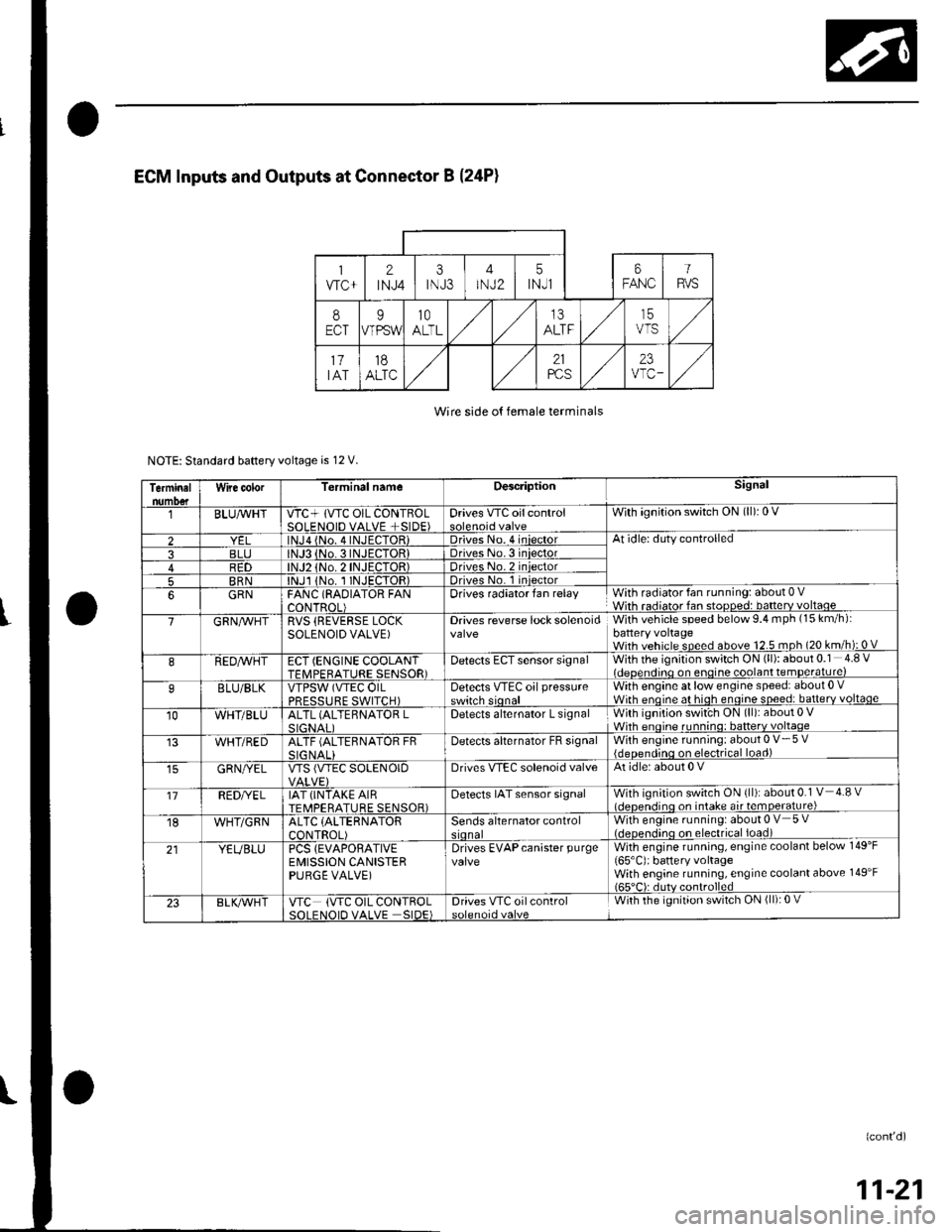
Wire side o{ female terminals
NOTE: Standard baftery voltage is 12 V.
Terminalnumo€tWire color[erminal nameDescriptionSignal
BLUAvHTVTC+ lVTC OIL CONTBOLSOLENOID VALVE +SIDE)Drives VTC oilcontrolWith ignition switch ON (ll): 0 V
2lNJa {No. 4INJECTOR)Driveso. 4 iniectorAt idle: duty controlled
3BLJo.3INJECTORIDriveso.3 iniector4R1)TOR)Driveso.2 iniector
5BRNlNJl 1No. I INJECTOR)Drives No. 1 iniector
6GRNFANC (RAOIATOR FANCONTROL)Drives radiator fan relayWith radiator fan running: about 0 VWith radiator fan stopped: batterv voltaoe
7GRN/vVHTRVS (REVERSE LOCKSOLENOID VALVE)Drives reverse lock solenoidWith vehicle speed below 9.4 mph (15 km/h):battery voltageWith vehicle speed above 12.5 mph (20 km/h): 0 V
8REDAVHTECT (ENGINE COOLANTTFMPFRATURE SENSOR)Detects ECT sensor signalWith the ignition switch ON (ll): about 0.1 4.8 Videoendino on enoine coolant temDerature)
9BLU/BLKVTPSW (VTEC OILPRFSSTIRF SWITCH)Detects VTEc oil pressureswitch sionalWith engine at low engine speed: about 0 .Wirh enoine at hioh enoine soeed: batterv voltaqe
10WHT/BLUALTL (ALTEBNATOR LSIGNAI IDetects alternator L signalWith ignition swit'ch ON (ll): about 0 VWhh enoine runnino: batterv voltaqe
WHT/REDALTF (ALTERNATOR FRSIG NALIDetecls alternator FB signalWith engine running: about 0 V- 5 V{deoendinq on electrical load)
GRN/YELVTS {VTEC SOLENOIDDrives VIEC solenoid valveAt idle: about 0 V
'17REDI/ELIAT (INTAKE AIRTEMPERATURE SENSOR)Detects IAT sensor signalWith ignition switch ON {ll): about 0.1 V 4.8 vl.lcnen.iino on intake air temoerature)
18WHT/GRNALTC (ALTERNATOR
CONTROL)Sends alternator controlWith engine running: about 0 V 5 V(.lcocn.lino on electrical ioad)
21YEUBLUPCS {EVAPORATIVEEMISSION CANISTERPURGE VALVE)
Drives EVAPcanister purgevalveWith engine running, engine coolant below 149'F
165'C): battery voltageWith engine running, engine coolant above 149'F165"C): dutv controlled
23BLK/Vr'HTVTC (VTC OIL CONTROLSOI FNOID VALVE SIDE)Drives VTC oilcontrolWith the ignition switch ON (ll): 0 V
(confd)
11-21
Page 229 of 1139
![HONDA CIVIC 2002 7.G Manual PDF Fuel and Emissions Systems
System Descriptions (contdl
ECM lnputs and Outputs at Connector E (31P}
L
u
1iMoFPR
2sr-{]zs3LG34SG3
6$1025HTC
1M RLY
8AFSHTCR
I
14FTP15ELD
16EPSLD
18ACC20Z/VBS21VSV
22BKSW HONDA CIVIC 2002 7.G Manual PDF Fuel and Emissions Systems
System Descriptions (contdl
ECM lnputs and Outputs at Connector E (31P}
L
u
1iMoFPR
2sr-{]zs3LG34SG3
6$1025HTC
1M RLY
8AFSHTCR
I
14FTP15ELD
16EPSLD
18ACC20Z/VBS21VSV
22BKSW](/img/13/5744/w960_5744-228.png)
Fuel and Emissions Systems
System Descriptions (cont'dl
ECM lnputs and Outputs at Connector E (31P}
L
u
1iMoFPR
2sr-{]zs3LG34SG3
6$1025HTC
1M RLY
8AFSHTCR
I
14FTP15ELD
16EPSLD
18ACC20Z/VBS21VSV
22BKSW23K-LINE24SEFMJ26NEP
21rMoCD
29scs30WEN31MIL
Wire side of female terminals
NOTE: Standard battery voltage is '12 V.
TerminalnumberWire colorferminal nameDescription Signal
GRNI/ELIMO FPR (IMMOBILIZERFLJEL PUMP RELAYIDrives PGM Fl main relay 20Vfor2 seconds after turning ignition switch ON{ll). then batterv voltaoe2WHT/REDSHO2S (SECONDARYHEATED OXYGEN SENSOR(SECONDARY HO2S),SENSOR 2r
Detects secondary HO2S{sensor 2) signalWith throttle Jully opened from idle with fullywarmed up engine: above 0.6VWith throttle quickly closed: below 0.4 V
3BRN/YELLG3 (LOGIC GROUND)cround forthe ECM/PCMcontrolcircuitLess than 1.0 V at all times
4PNKSG3 {SENSOR GBOUND)Sensor oroundLess than 1.0 V at all times5YEUELUVCC3 {SENSOR VOLTAGE)Provides sensor voltageWith ignition switch ON (ll): about 5 VWith ionition switch OFF: about 0 V6BLKATr'HTSO25HTC (SECONDARYHEATED OXYGEN SENSOR(SECONDARY H02S)HEATER CONTROL)
Drives secondary HO2SheaterWith ignition switch ON (ll): baftery voltageWilh fullv warmed up engine running: dul,controlled
1REDA/ELMRLY (PGM.FI MAINRELAY}Drives PGM-Flmain relay 1Power source forthe DTCWith ignition switch ON (ll): about 0 VWith ignition switch OFF: battery voltage
IORNAFSHTCR {AIR FUEL BATIO(Iy'F)SENSOR HEATERCONTROL RELAY)
Drives air fuel ratio sensorheater relayWith ignition swirch ON {ll): 0 V
IYEUBLKIGl (IGNITION SIGNAL)Detecrs ignition signalWith ignition switch ON (ll): battery voltageWith iqnition switch OFF: about 0 V't4LT GRNFIP lFUEL TANKPRESSURE (FTP) SENSOR)Detects FTP sensor signalWith ignition switch ON (ll) and fuel fill cap open:about 2.5 VGRN/REDELD (ELECTRICAL LOADDETECTOF)Detects ELD signalWith ignition swjtch ON itt):aOoutO.t V l-gV(deDendino on electrical load)LT GRN/8LKEPSLD (ELECIRICALPOWEB STEEBING LOADDETECT)
Detects Power steering loadsrgnalAt idle with steering wheel in straight aheadposition: about 0 VAt idle with steering wheelatfull lock: momentary
'18REDACC (Ay'C CLUTCH RELAY)Drives P,/C clutch relayWith compressor ON: about 0 VWith comoressor OFF: batterv voltaoe
11-22
\-
Page 247 of 1139
![HONDA CIVIC 2002 7.G Manual PDF Fuel and Emissions Systems
System Descriptions (contdl
ECM Circuit Diagram {contd)
\
-{ffi]---1t-|
IATSENSOR
-{El------l
ECTSENSOS
T_""",,..
I-BFN/YEL
ft^--l
,","., J t-|:I REVERSEI LocKI soleloto+ HONDA CIVIC 2002 7.G Manual PDF Fuel and Emissions Systems
System Descriptions (contdl
ECM Circuit Diagram {contd)
\
-{ffi]---1t-|
IATSENSOR
-{El------l
ECTSENSOS
T_""",,..
I-BFN/YEL
ft^--l
,","., J t-|:I REVERSEI LocKI soleloto+](/img/13/5744/w960_5744-246.png)
Fuel and Emissions Systems
System Descriptions (cont'dl
ECM Circuit Diagram {cont'd)
\
-{ffi]---1t-|
IATSENSOR
-{El------l
ECTSENSOS
T_""",,..
I-BFN/YEL
ft^--l
,","., J t-|':I REVERSEI LocKI soleloto+ vaLvE
t!j]]
CMPSENSOAA
L-IJUNCTIONI CONNECTOR
-
11-40
Page 287 of 1139
PGM-Fl System
6.
1.
DTC Troubleshooting (cont'dl
DTC P0500: VSS Circuit Malfunction
1. Test-drive the vehicle.
2. Check the vehicle speed with the scan tool.
ls the correct speed indicated?
YES-lntermiftent failure, system is OK at this time.
Check for poor connections or loose terminals at
the VSS and at the ECM.I
NO Go to step 3.
3. Turn the ignition switch OFF.
4. Block the rear wheels, and set the parking brake.
5. Raise the front ofthe vehicle, and make sure it is
securely supported,
Turn the ignition switch ON (ll).
Block the right front wheel, and slowly rotate the
left front wheel.
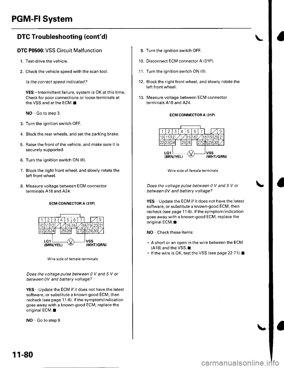
8. Measure voltage between ECM connector
terminals A18 and A24.
ECM CONNECTOR A {31P)
Wire side of female terminals
Does the voltage pulse between 0 V and 5 V or
between 0V and battery voltage?
YES-Update the ECM if it does not have the latest
software, or substitute a known-good ECM. then
recheck (see page 1 1-6). lf the symptom/indication
goes away with a known-good ECM, replace the
original ECN4.l
NO Go to step 9.
11-80
9. Turn the ignition switch OFF.
10. Disconnect ECM connector A (3'1P).
1 1. Turn the ignition switch ON {ll}.
12. Blockthe right front wheel. and slowly rotate the
left front wheel.
'!3. lMeasure voltage between ECM connector
terminals A18 and A24.
ECM CONNECTOR A I31PI
Wire side of female terminals
Does the voltage pulse between 0 V and 5 V ol
between 0V and battety voltage?
YES Update the ECM if it does not have the latest
software, or substitute a known-good ECM, then
recheck (see page 1 1-6). lf the symptom/indication
goes away with a known-good ECM, replace the
origlnal ECM.I
NO Check these items:
. A short or an open in the wire between the ECM
(A18) and the VSS.I. lf thewire is OK,testtheVSS (see page 22 71).1
Page 342 of 1139
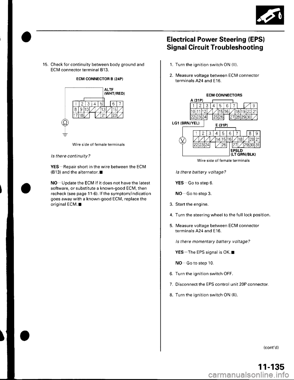
15. Check for continuity between body ground and
ECIM connector terminal 813.
ECM CONNECTOR B I24P}
Wire side of female terminals
ls there continuity?
YES Repair short in the wire between the ECM
(813) and the alternator.l
NO Update the ECM if it does not have the latest
software, or substitute a known-good ECM, then
recheck lsee page 1 1-6). lf the symptom/indication
goes away with a known-good ECM, replace the
original ECM.I
Electrical Power Steering (EPSI
Signal Circuit Troubleshooting
Turn the ignition switch ON (ll).
l\4easure voltage between ECM connector
terminals 424 and E16.
1.
2.
3.
4.
5.
Wire side of female terminals
ls there battery voltage?
YES Go to step 6.
NO Go to step 3.
Start the engine.
Turn the steering wheel lo the full lock position.
l\4easure voltage between ECM connector
terminals A24 and E16.
ls there momentaty battery voltage?
YES The EPS signal is OK.t
NO Go to step 10.
6. Turn the ignition switch OFF.
7. Disconnect the EPS control unit 20P connector.
8. Turn the ignition switch ON (ll).
(cont'd)
11-135
Page 351 of 1139
FuelSupply System
Fuel Pressure Relieving
Before disconnecting fuel lines or hoses, relieve
pressure from the system by disconnecting the fuel
tube/quick connect fitting in the engine compartment.
1. Turn the ignition switch OFF,
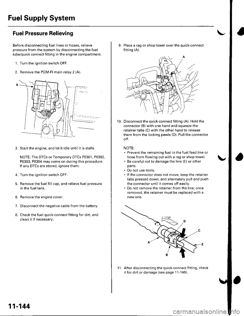
2. Remove the PGM-Fl main relay 2 (A).
Startthe engine, and let it idle until it is stalls.
NOTE: The DTCS or Temporary DTCS P0301. P0302,
P0303, P0304 may come on during this procedure.
lf any DTCS are stored, ignore them.
Turn the ignition switch OFF.
Remove the fuel fill cap, and relieve fuel pressure
in the fueltank.
Remove the engine cover.
Disconnect the negative cable from the battery.
Check the fuel quick-connect fitting for dirt, and
clean it if necessary.
3.
4.
6.
7.
8.
11-144
11
10.
9. Place a rag or shop towel over the quick-connect
fitting (A).
Disconnect the quick-connect fifting (A): Hold the
connector (B) with one hand and squeeze the
retainer tabs (C) with the other hand to release
them from the locking pawls {D). Pullthe connector
off.
NOTE:. Prevent the remaining fuel in the fuel feedlineor
hose from flowing out with a rag or shop towel.. Be careful notto damage the line (E) or other
pa rts.. Do not use tools.. lf theconnectordoes not move, keepthe retainer
tabs pressed down, and alternately pull and push
the connector until it comes off easily.. Do not remove the retainer from the line; once
removed, the retainer must be replaced with a
new one.
After disconnecting the quick-connect fifting, check
it for dirt or damage (see page 1 1-149).
Page 353 of 1139
Fuel Supply System
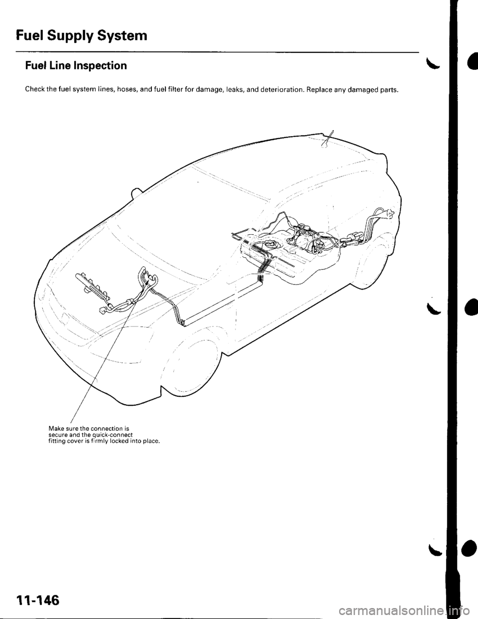
Fuel Line Inspection
Check the fuel system lines, hoses, and fuel filter for damage, leaks, and deterioration. Replace any damaged parts.
Make sure the connection issecure and the quick-connectfitting cover is firmly locked into place.
\
11-146
Page 356 of 1139
2.
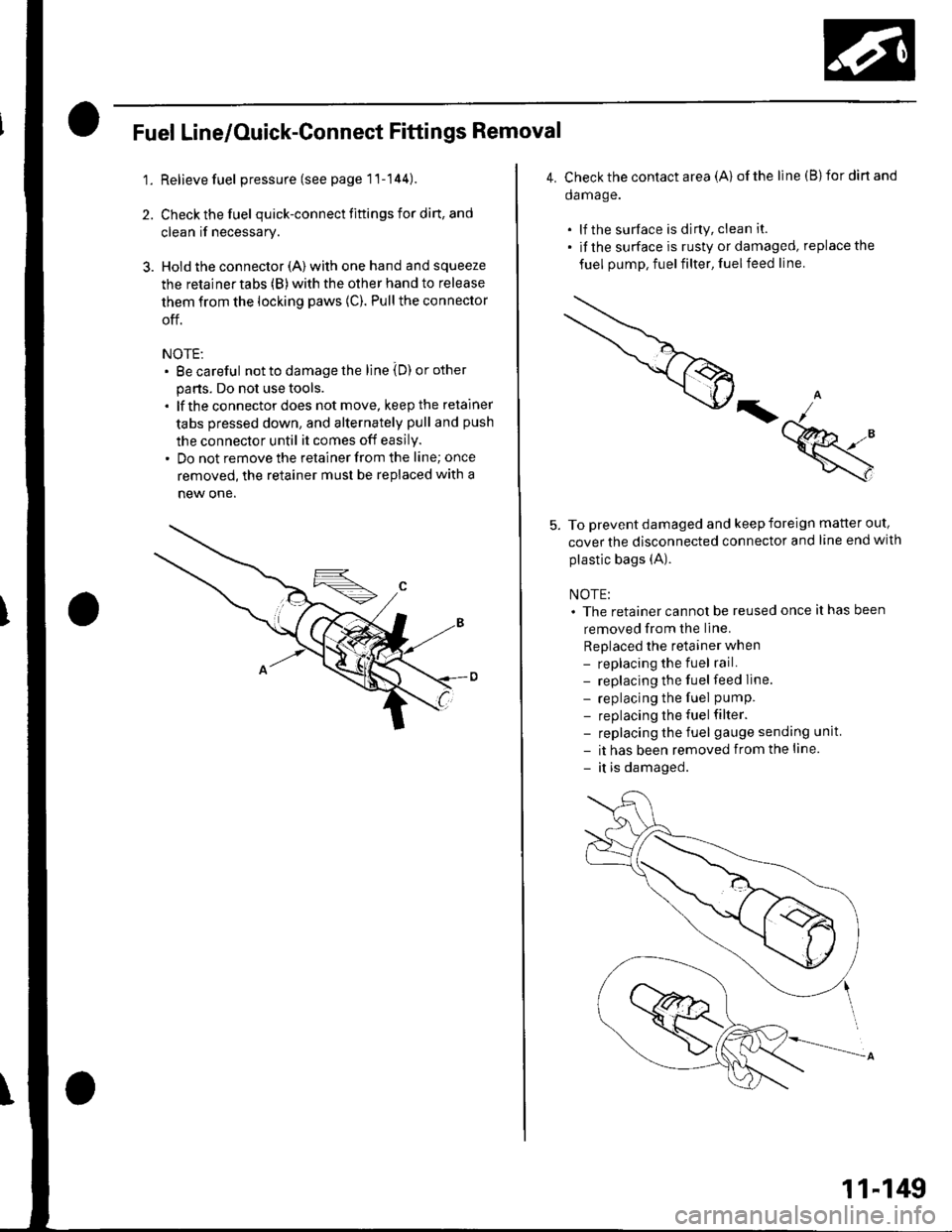
Fuel Line/Ouick-Gonnect Fittings Removal
1. Relieve fuel pressure (see page 1'l-144).
Check the fuel quick-connect fiftings for din, and
clean if necessary.
Hold the connector (A) with one hand and squeeze
the retainertabs (B)with the other hand to release
them from the locking paws (C). Pull the connector
off.
NOTE:. Be careful not to damage the line iD) or other
parts. Do not use tools.. lf the connectordoes not move, keep the retainer
tabs pressed down, and alternately pull and push
the connector until it comes off easily.. Do not remove the retainer from the line; once
removed, the retainer must be replaced with a
new one.
4. C heck the contact a rea (A) of the line (B)for dirt and
da mage.
. lf the surface is dirty, clean it.. if the surface is rusty or damaged, replace the
fuel pump, fuelfilter, fuelfeed line.
=k
To prevent damaged and keep foreign matter out,
cover the disconnected connector and line end with
plastic bags (A).
NOTE:. The retainer cannot be reused once it has been
removed from the line.
Replaced the retainer when- replacing the fuel rail.- replacing the fuel feed Iine.
- replacing the fuel pumP.
- replacing the fuel filter.- replacing the fuel gauge sending unit
- it has been removed from the line.
- it is damaged.
11-149
Page 358 of 1139
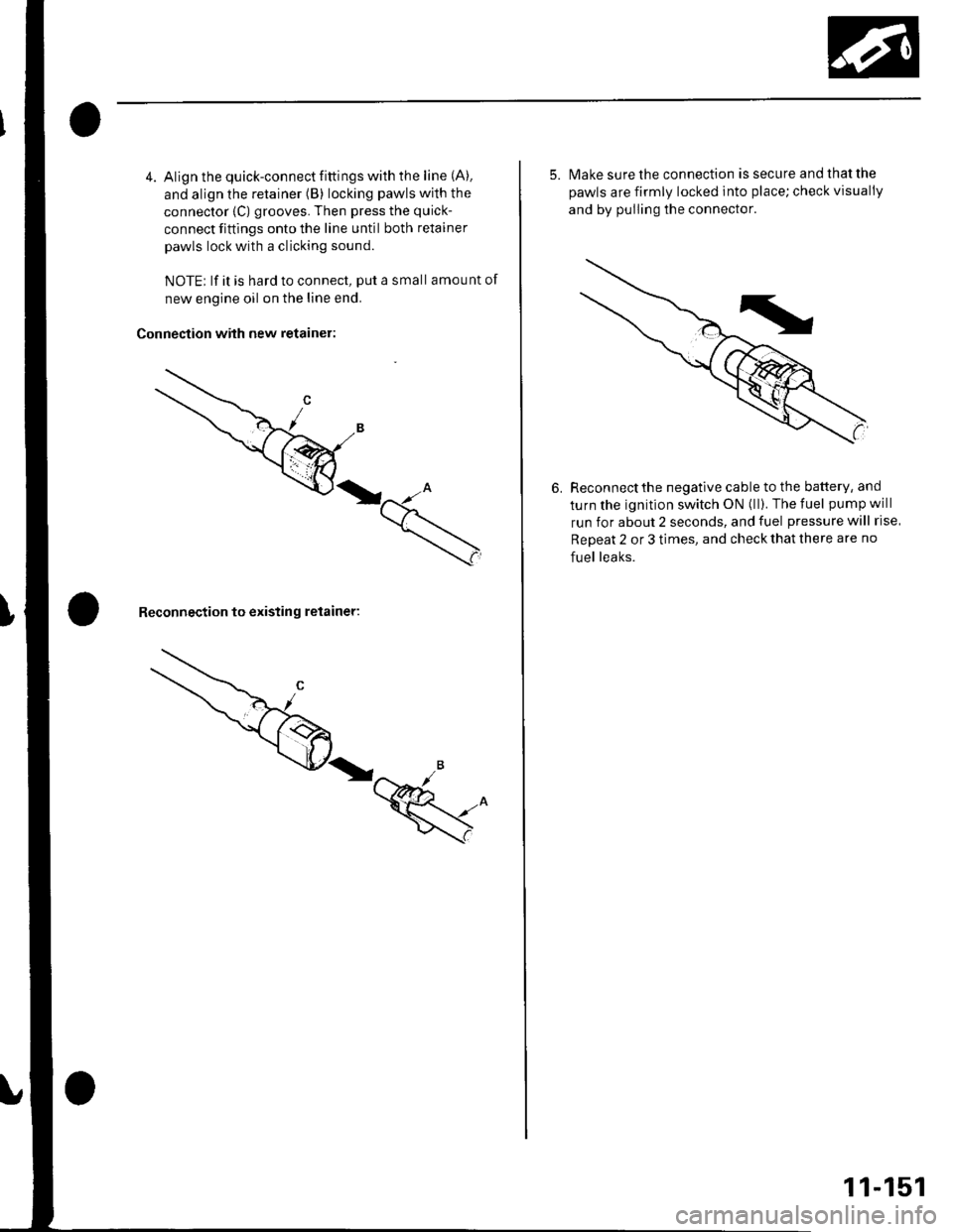
4. Align the quick-connect fittings with the line (A).
and align the retainer (B) locking pawls with the
connector {C) grooves. Then press the quick-
connect fittings onto the line until both retainer
pawls lock with a clicking sound.
NOTE; lf it is hard to connect, put a small amount of
new engine oil on the line end.
Connection with new retainer:
Reconnection to existing retainer:
5. lvlake sure the connection is secure and that the
pawls are firmly locked into place; check visually
and by pulling the connector.
6. Reconnectthe negative cable to the battery, and
turn the ignition switch ON (ll). The fuel pump will
run for about 2 seconds, and fuel pressure will rise
Repeat 2 or 3 times, and check that there are no
fuel leaks.
11-151
Page 359 of 1139
Fuel Supply System
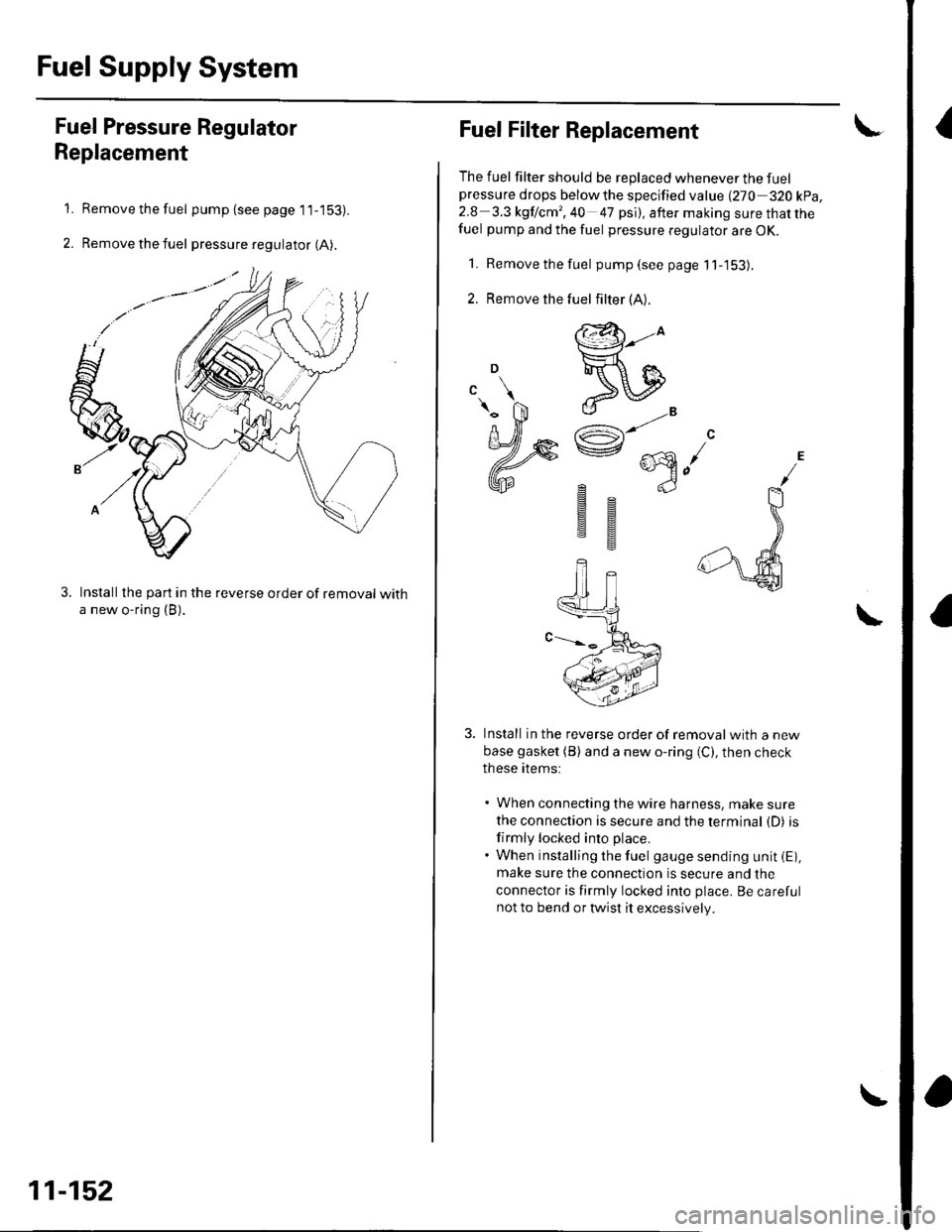
{Fuel Pressure Regulator
Replacement
Remove the fuel pump (see page 1 1-153).
Remove the fuel pressure regulator (A).
Installthe part in the reverse order of removal witha new o-ring (B).
1.
2.
11-152
Fuel Filter Replacement
The fuel filter should be replaced whenever the fuelpressure drops belowthe specified value {270 320 kpa,2.8 3.3 kgf lcm', 40 47 psi), after making sure that thefuel pump and the fuel pressure regulator are OK.
1. Remove the fuel pump(seepagell-'153).
2. Remove the
Install in the reverse order of removalwith a new
base gasket (B) and a new o-ring (C), then check
these items:
' When connecting the wire harness, make sure
the connection is secure and the terminal (D) is
firmly locked into place.. When installing the fuel gauge sending unit iE),make sure the connection is secure and the
connector is firmly locked into place. Be carefulnot to bend or twist it excessively.
\
fuel filter (A).
@-to
ReIJ
e"^AR^ ...\e @n-)
gs
sg