lock HONDA CIVIC 2002 7.G Manual Online
[x] Cancel search | Manufacturer: HONDA, Model Year: 2002, Model line: CIVIC, Model: HONDA CIVIC 2002 7.GPages: 1139, PDF Size: 28.19 MB
Page 360 of 1139
Fuel Pump/Fuel Gauge Sending Unit Replacement
SpecialTools Required
Fuel sender wrench 07XAA-001010A
1.Relieve the fuel pressure (see page 11-144).
Remove the fuel fill cap.
Remove the seat cushion (see page 20-80).
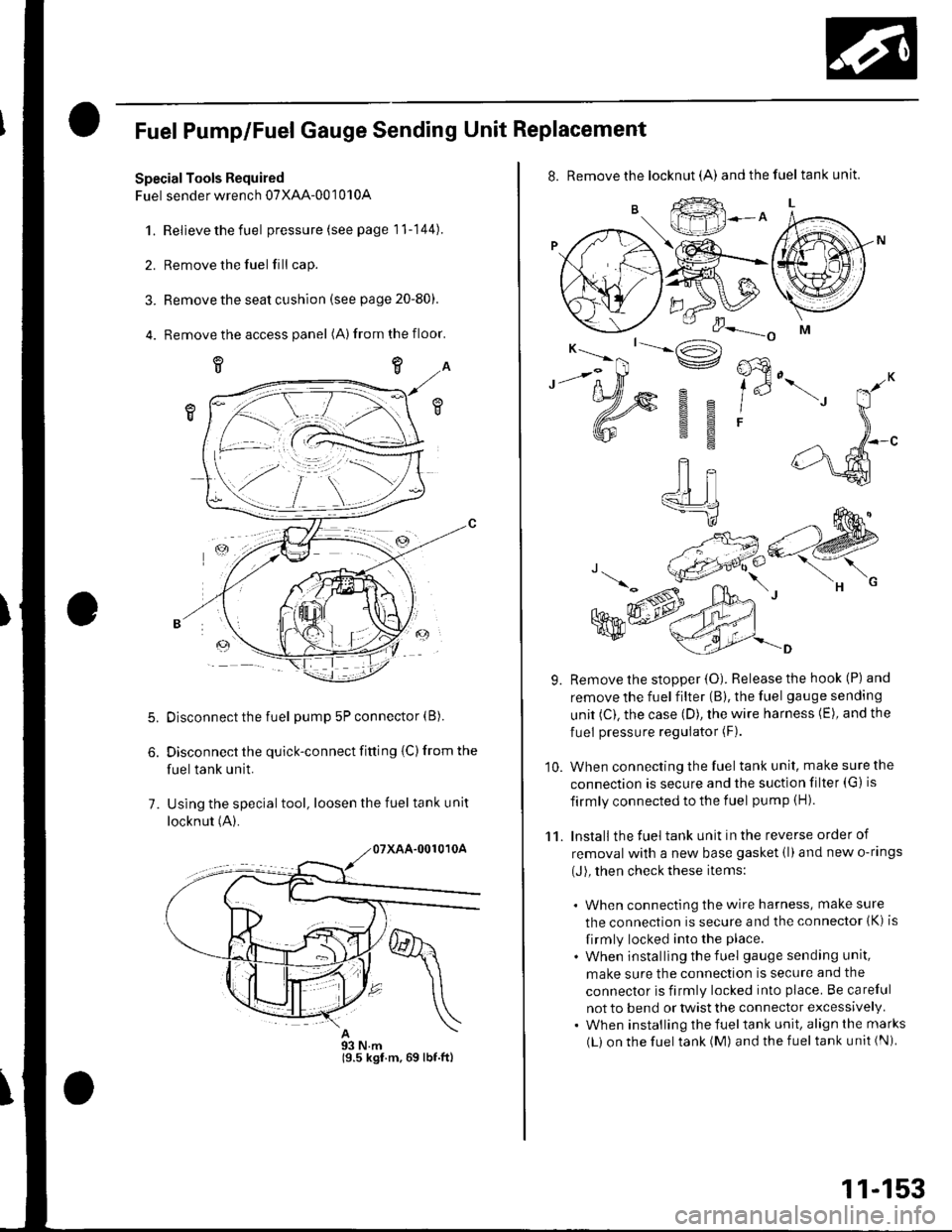
Remove the access panel (A)from the floor.
5.
7.
Disconnect the fuel pump 5P connector (B).
Disconnect the quick-connect fitting {C) from the
fuel tank unit.
Using the special tool, loosen the fuel tank unit
locknut (A).
93 N.m19.5 kgf.m,69 lbf.ftl
11-153
8. Remove the locknut (A) andthefuel tankunit.
9. Remove the stopper {O). Release the hook (P) and
remove the fuel filter (B), the fuel gauge sending
unit (C). the case (D), the wire harness (E), and the
fuel pressure regulator (F).
10. When connecting the fuel tank unit, make sure the
connection is secure and the suction filter (G) is
firmly connected to the f uel pump (H).
11. Install the fuel tank unit in the reverse order of
removal with a new base gasket (l)and new o-rings
(J), then check these items:
. When connecting the wire harness, make sure
the connection is secure and the connector (K) is
firmly locked into the place.
. When installing the f uel gauge sending unit,
make sure the connection is secure and the
connector is firmly locked into place. Be careful
not to bend or twist the connector excessively.. When installing the fueltank unit, align the marks
(L) on the fuel tank (M) and the fuel tank unit (Ni
Page 364 of 1139
10. Checkthatthe pointerof thefuel gauge indicates"F".
. lf the pointer does not indicate "F", replace the
ga uge.. lf the pointer indicates "F", inspect the fuel
gauge sending unit.
NOTE: The pointer of the fuel gauge retu rns to the
bottom of the gauge dial when the ignition switch
is OFF, regardless of the fuel level. -
11. Relieve the fuel pressure (see page 11-144\.
12. Remove the fuelfill cap.
13. Disconnect the quick-connect fittings from the fuel
pump.
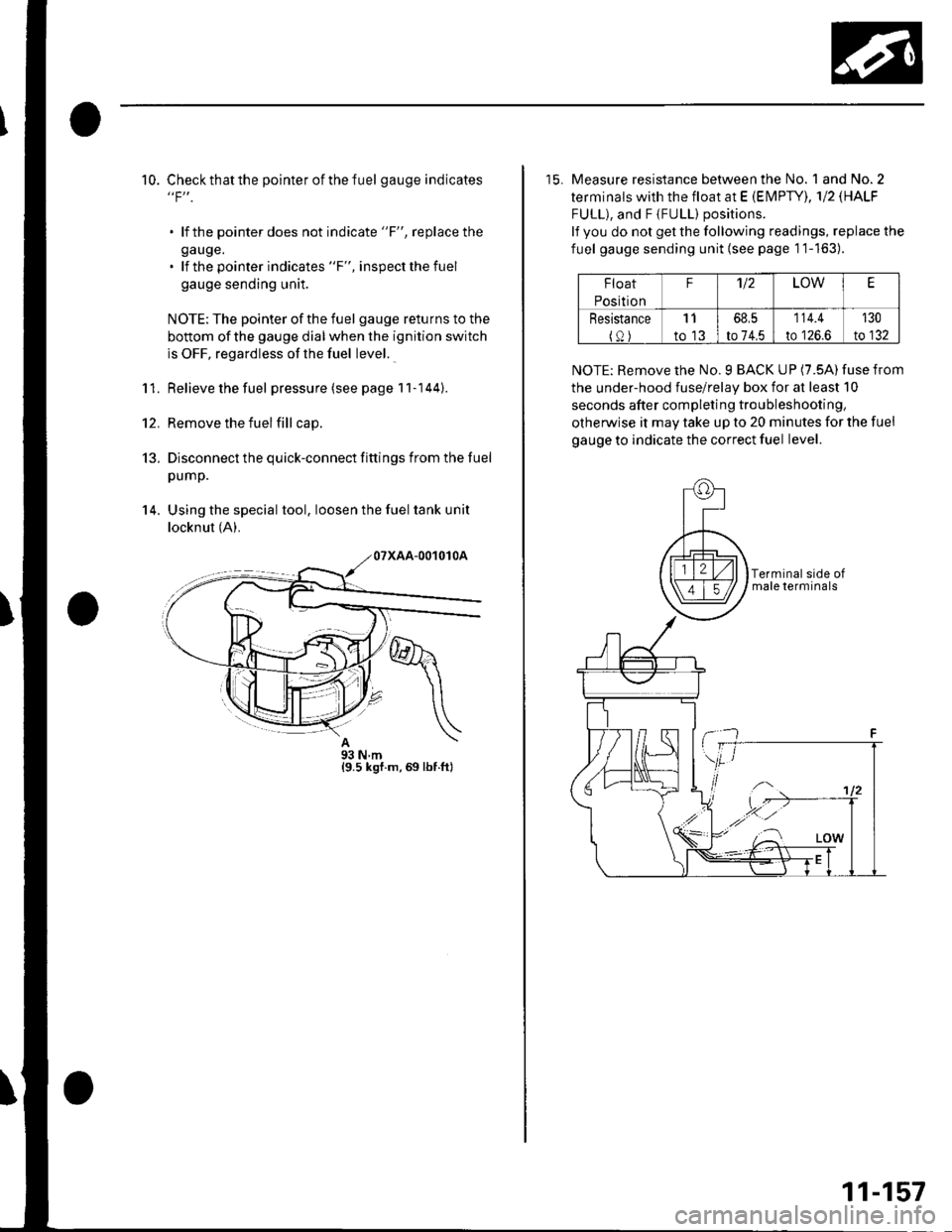
14. Using the special tool, loosen the fuel tank unit
locknut (A).
A93Nm{9.5 ksf.m,69 lbf.ft}
15. Measure resistance between the No. 1 and No.2
terminals with the float at E (EN4PTY), 'l12 \HALF
FULL), and F {FULL) positions.
lf you do not get the following readings, replace the
fuel gauge sending unit {see page 1'1-163).
Float
Position
F'U2LOWE
Resistance
{0)
11
to 13
68,5
to 74.5
114.4
to 126.6
130
to 132
NOTE: Remove the No. 9 BACK UP (7.5A) fuse from
the under-hood fuse/relay box for at least 10
seconds after completing troubleshooting,
otherwise it may take up to 20 minutes for the fuel
gauge to indicate the correct fuel level.
11-157
Page 370 of 1139
Throttle Cable Adjustment
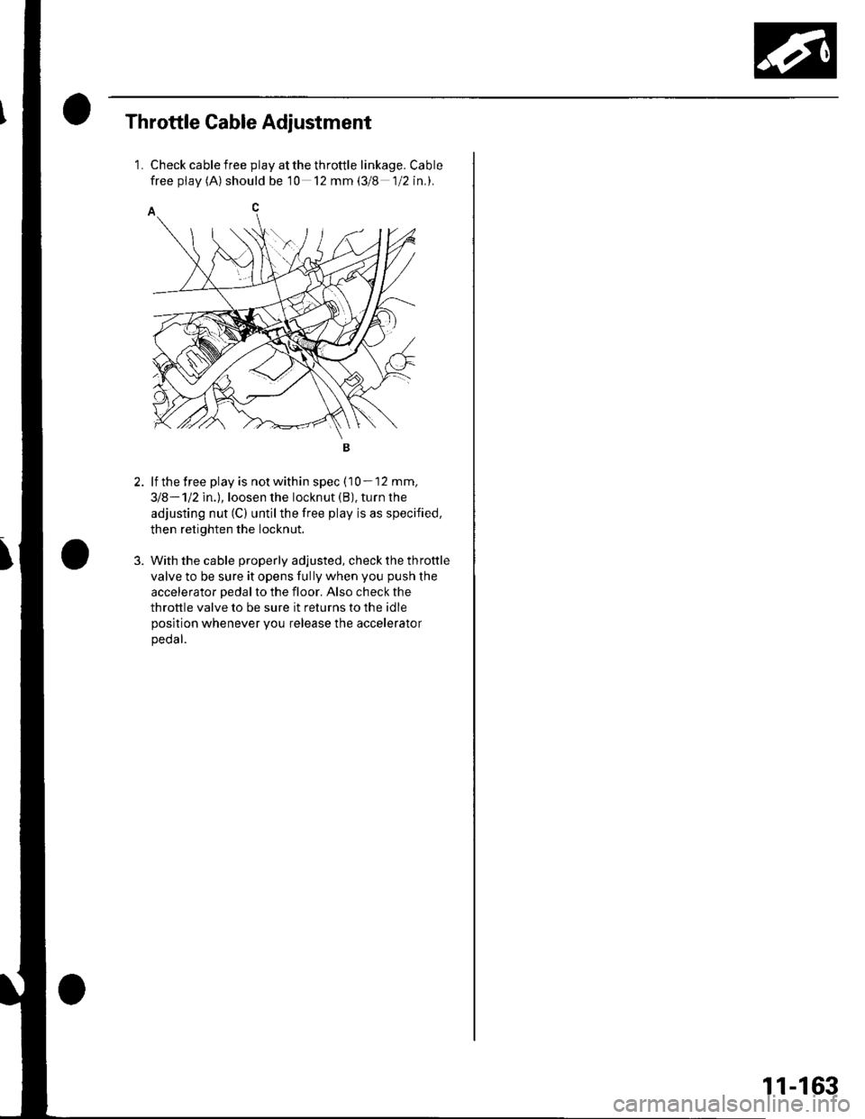
1.Check cable free play at the throttle linkage. Cable
free pf av (A) should be 10 12 mm (3/8 1/2 in.).
lf the free play is not within spec (10 - 12 mm,
318-112ln.l,loosen the locknut (B), turn the
adjusting nut (C) untilthe free play is as specified,
then retighten the locknut.
With the cable properly adjusted, check the throttle
valve to be sure it opens fully when you push the
accelerator pedal to the floor. Also check the
throttle valve to be sure it returns to the idle
position whenever you release the accelerator
peoar.
11-163
Page 371 of 1139
Intake Air System
Throttle Cable Removal/lnstallation
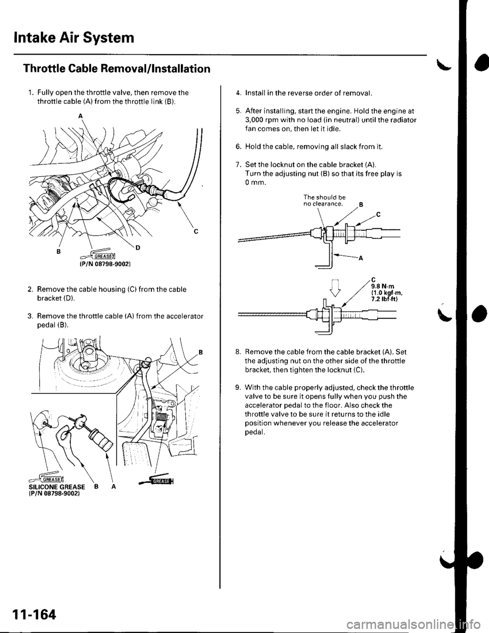
1. Fully open the throttle valve, then remove the
throttle cable (A) from the throttle link (B).
Remove the cable housing (C)from the cable
bracket (D).
Remove the throttle cable (A)from the accelerator
pedal (B).
2.
3.
SILICONE GREASE B(P/N 08798-9002)
(P/N 08?98-9002)
11-164
5.
Install in the reverse order of removal.
After installing, start the engine. Hold the engine at
3,000 rpm with no load (in neutral) untilthe radiator
fan comes on, then let it idle.
Hold the cable, removing all slack from it.
Set the locknut on the cable bracket {A).Turn the adjusting nut (B) so that its free play is
0 mm.
The should beno crearance.
Remove the cable from the cable bracket (A). Set
the adjusting nut on the other side of the throttle
bracket, then tighten the locknut {C}.
With the cable properly adjusted, check the throttle
valve to be sure it opens fully when you push the
accelerator pedal to the floor. Also check the
throttle valve to be sure it returns to the idle
position whenever you release the accelerator
Deoat.
7.
!
8.
9.
('1.0 kgf.m,7.2 tbf.ftl
Page 398 of 1139
Clutch
Special Tools ......... 12-2
Comoonent Location Index .......................,............. 12-3
Clutch Pedal, Clutch Pedal Position Switch, and
Clutch Interlock Switch Adiustment .................... 12-4
Cf utch Master Cylinder Rep|acement ..................... 12-5
Slave Cylinder Replacement .'........ 12-7
Clutch Replacement ................... ..... 12-9
Page 400 of 1139
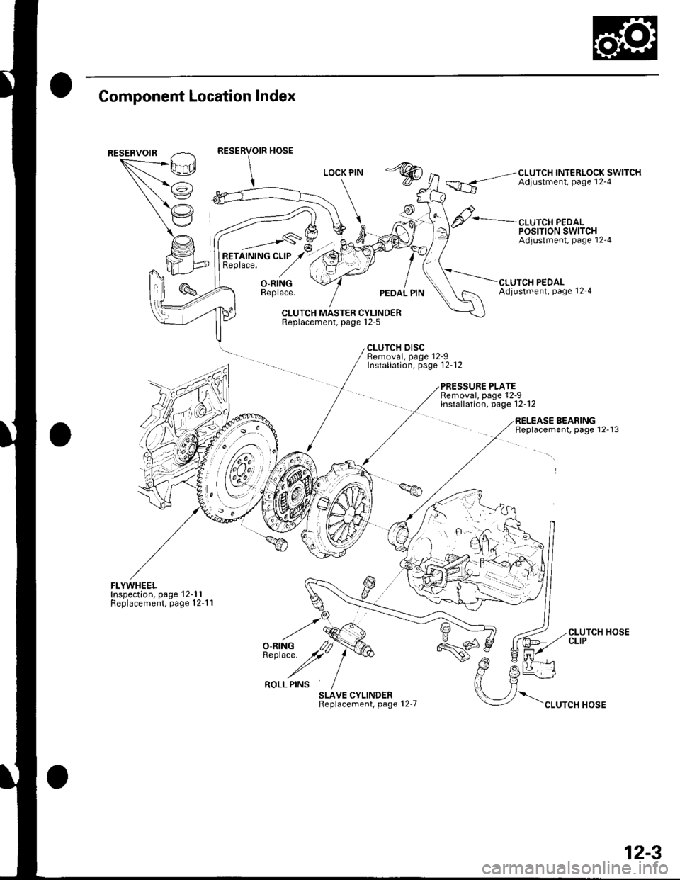
Component Location Index
""*--/\,L_.Ei
/i
(,'.'
CLUTCH INTERLOCK SWITCHAdjustment, page 12-4
CLUTCH PEDALPOSTTTON SWITCHAdjustment, page'12-4
RETAINING CLIPReplace.
_,___-,-s\
O-RINGReplace.UTCH PEDALAdjustment, Page 12 4
CLUTCH MASTER CYLINDERReplacement, page l2-5
CLUTCH DISCBemoval, page 12-9Installation, page'12-12
PRESSURE PLATERemoval, page'12-9lnstallation, page 12-12
FLYWHEELInspection, page'12-1 1Replacement, page 12-1 1
SLAVE CYLINDERReplacement, page 12-7
RELEASE BEARINGBeplacement, page 12-13
\".rr"*"o*
CLUTCH HOSECLIP
12-3
Page 401 of 1139
Clutch
Clutch Pedal, Clutch
Adjustment
NOTE:. To check the clutch pedal position switch(see page 4-45).. To check the clutch interlock switch (see page 4-6).. Remove the driver's side floor mat before adjusting
the clutch pedal.. The clutch is self-adjusting to compensate for wear.. lf there is no clearance betweenthe mastercylinderpiston and push rod, the release bearing will be held
against the diaphragm spring. which can result in
clutch slippage or other clutch problems.
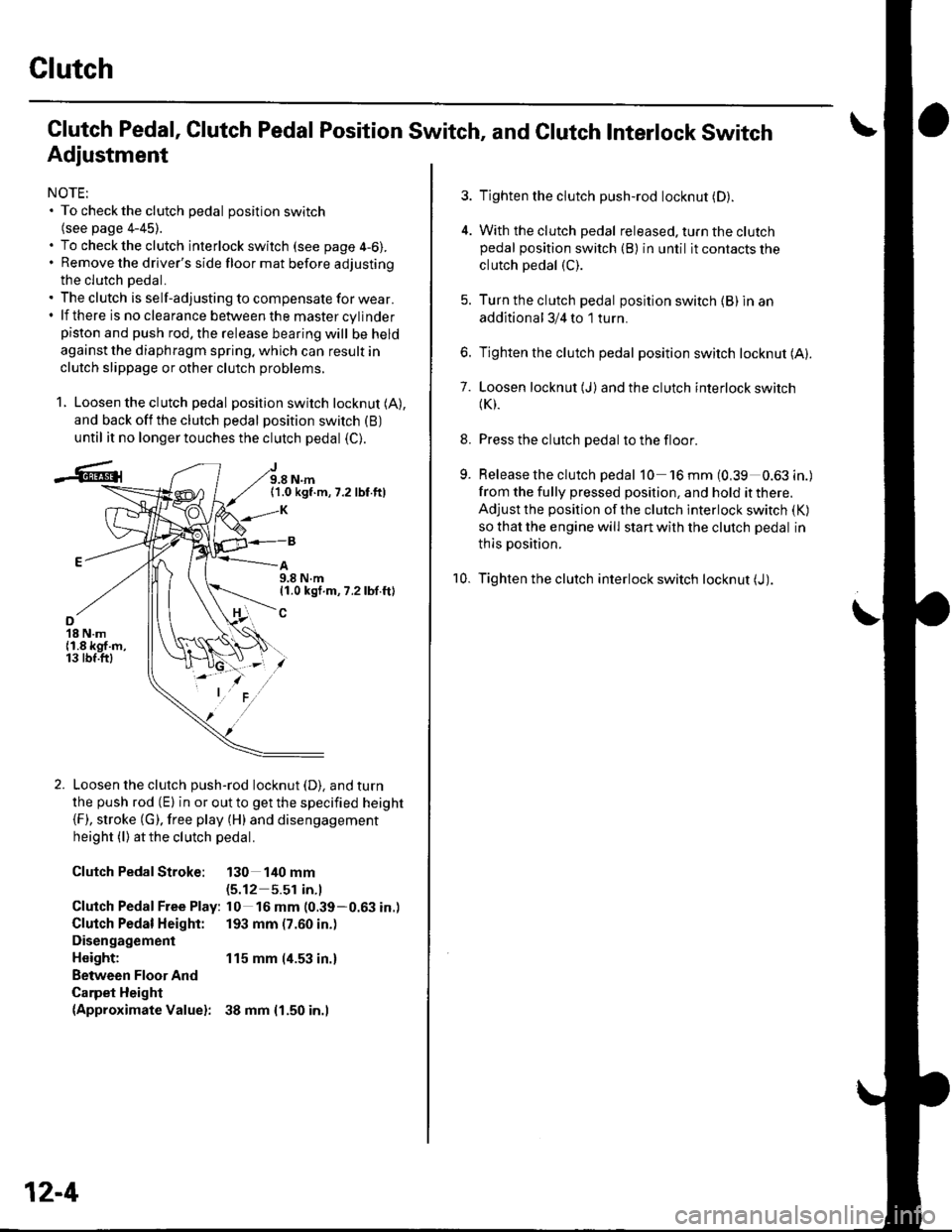
1. Loosen the clutch pedal position switch locknut (A),
and back off the clutch pedal position switch (B)
until it no longer touches the clutch pedal (C).
J9.8 N.m(1.0 kgf.m,7.2 lbf.ft)
A9.8 N.m11.0 kgf.m, 7.2 lbf.ft)
o18 N.m{1.8 kgf.m,13 tbf.ftl
Loosen the clutch push-rod locknut (D). and turn
the push rod (E) in or out to get the specified height(F), stroke (G). free play (H) and disengagement
height (l) atthe clutch pedal.
Clutch PedalStroke: 130 140 mm(5.12 5.51 in.l
Clutch Pedal Free Play: l0 16 mm (0.39-0.63 in.)
Clutch Pedal Height: 193 mm (7.60 in.)
Disengagement
Height: 115 mm (4.53 in.)
Between Floor And
Carpet Height(Approximate Valuel: 38 mm {1.50 in.l
12-4
Pedal Position Switch, and Clutch Interlock Switch
3. Tighten the clutch push-rod locknut (D).
4. With the clutch pedal released. turn the clutchpedal position switch (B) in until it contacts the
clutch pedal (C).
5. Turn the clutch pedal position switch {B) in an
additional 3/4 to 1 turn.
6. Tighten the clutch pedal position switch locknut (A).
7. Loosen locknut (J)and the clutch interlock switch(K).
8. Press the clutch pedal to the floor.
9. Release the clutch pedal 10 'l6mm(0,39 0.63in.)
from the fully pressed position, and hold it there.
Adjust the position of the clutch interlock switch (K)
so that the engine will start with the clutch pedal in
thls position.
10. Tighten the clutch interlock switch locknut (J).
Page 402 of 1139
Clutch Master Cylinder Replacement
NOTE: Do not spill brake fluid on the vehicle; it may
damage the paint; if brake fluid does contact the paint,
wash it off immediatelV with water.
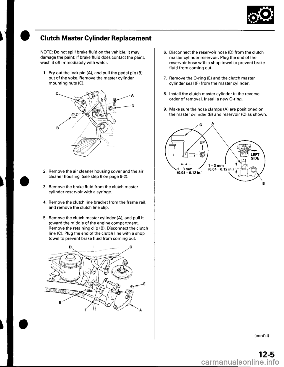
1. Pry out the lock pin (A), and pullthe pedal pin (B)
out of the yoke. Remove the master cylinder
mounting nuts (C).
Remove the air cleaner housing cover and the air
cleaner housing (see step 6 on page 5-2).
Remove the brake fluid from the clutch master
cylinder reservoir with a syringe.
Remove the clutch line bracket from the frame rail,
and remove the clutch line clip.
Remove the clutch master cylinder (A), and pull it
toward the middle of the engine compartment.
Remove the retaining clip (B). Disconnect the clutch
line (C). Plug the end of the clutch line with a shop
towelto prevent brake fluid from coming out.
g-E
3.
6. Disconnect the reservoir hose (D) fromtheclutch
master cylinder reservoir. Plug the end of the
reservoir hose with a shop towel to prevent brake
fluid from coming out.
7. Remove the O-ring (E) and the clutch master
cylinder seal (F) from the master cylinder.
8. Installthe clutch master cylinder in the reverse
order of removal. Install a new O-ring.
9. Make sure the hose clamps (A) are positioned on
the master cylinder (B) and reservoir (C) as shown.
(cont'd)
UP
i
12-5
Page 405 of 1139
Clutch
Slave Cylinder Replacement (cont'd)
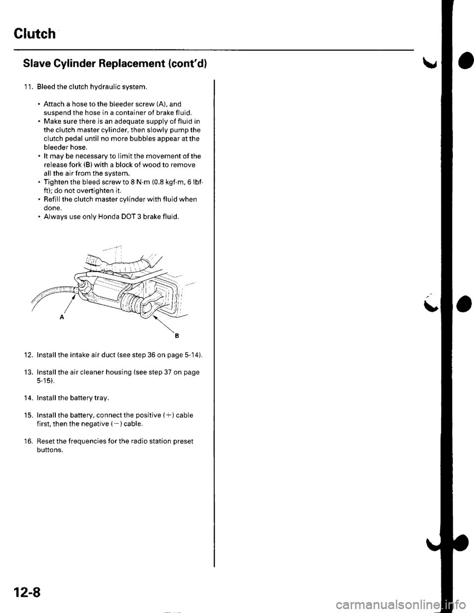
11. Bleed the clutch hydraulic system.
. Aftach a hose to the bleeder screw (A), and
suspend the hose in a container of brake fluid.. Make sure there is an adequate supply offluid in
the clutch master cylinder, then slowly pump the
clutch pedal until no more bubbles appear atthe
bleeder hose.. lt may be necessary to llmit the movement of the
release fork (B) with a block of wood to remove
all the air from the system.. Tighten the bleed screw to I N.m (0.8 kgf.m, 6 lbf
ft); do not ovenighten it,. Refill the clutch master cylinder with fluid when
done.. Always use only Honda DOT 3 brake fluid.
Install the intake air duct (see step 36 on page 5-14).
Installthe air cleaner housing (see step 37 on page
5-15).
Install the battery tray.
Install the battery, connect the positive (+) cable
first, then the negative (- ) cable.
Reset the frequencies for the radio station preset
buttons,
12.
13.
14.
t5.
16.
12-8
L
Page 415 of 1139
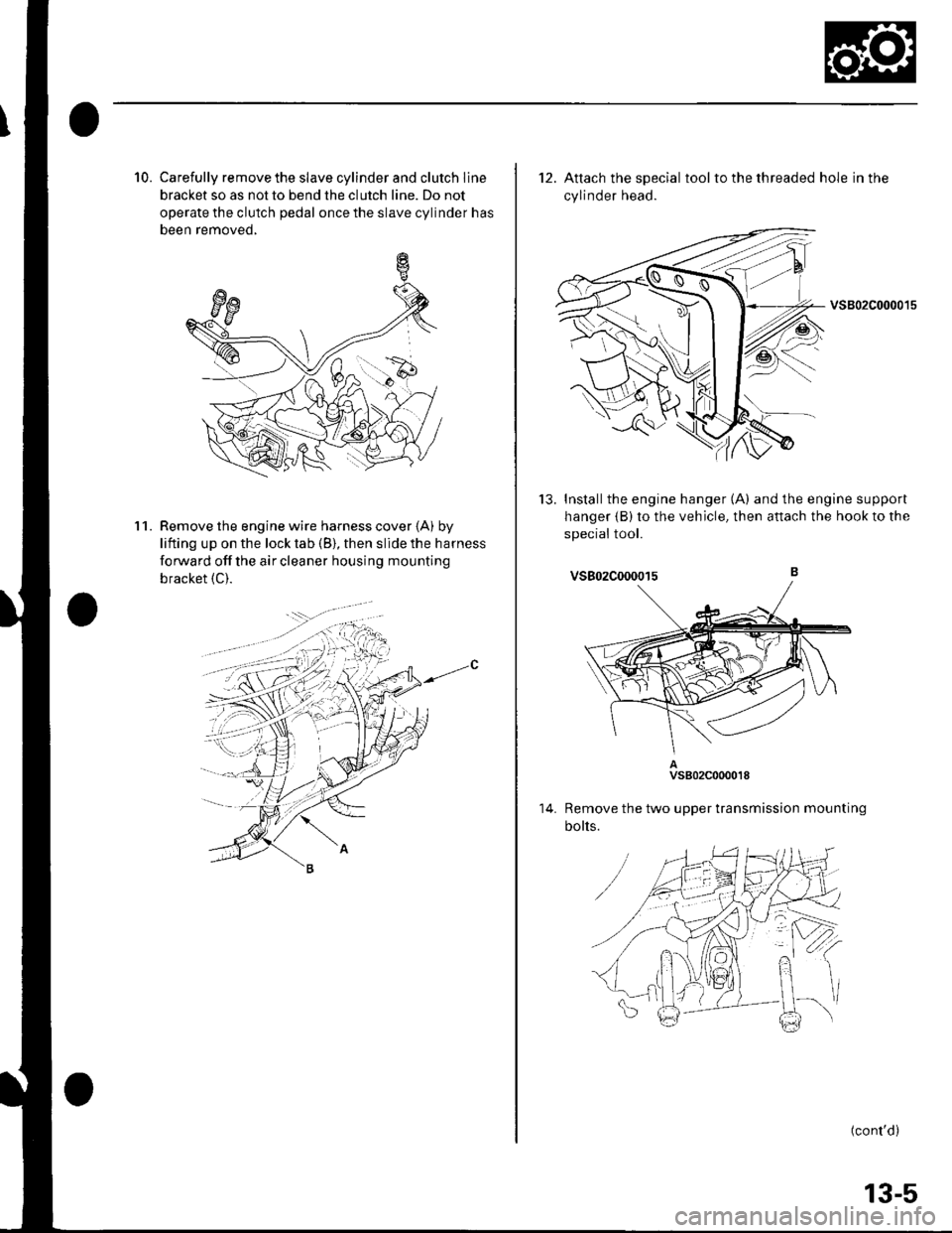
10. Carefully remove the slave cylinder and clutch line
bracket so as not to bend the clutch line. Do not
operate the clutch pedal once the slave cylinder has
been removed,
Remove the engine wire harness cover (A) by
lifting up on the lock tab (B), then slide the harness
forward offthe aircleaner housing mounting
bracket {C).
11.
12. Attach the special tool to the threaded hole in the
cylinder head.
vsB02c00001s
Installthe engine hanger (A) and the engine support
hanger {B) to the vehicle, then attach the hook to the
sDeciai tool.
tJ.
14.
vs802c000015
Remove the two upper transmission mounting
bolts.
(cont'd)
13-5