lock HONDA CIVIC 2002 7.G Workshop Manual
[x] Cancel search | Manufacturer: HONDA, Model Year: 2002, Model line: CIVIC, Model: HONDA CIVIC 2002 7.GPages: 1139, PDF Size: 28.19 MB
Page 1021 of 1139
sRs
Precautions and Procedures
General Precautions
Please read the following precautions carefully beforeperforming airbag system service. Observe theinstructions described in this manual. or the airbags
could accidentally deploy and cause damage or injuries.
. Except when performing electrical inspections.
always turn the ignition switch OFF, disconnect the
negative cable from the battery, and wait at least 3minutes before beginning work.
NOTE: The memory is not erased even if the ignition
switch is turned OFF or the battery cables are
disconnected from the battery.. Use replacement pans which are manufactured to the
same standards and quality as the original parts. Do
not install used SRS parts from another vehicle. Useonly new pans when making SRS repairs.. Carefully inspect any SRS part before you install it.
Do not install any part that shows signs of being
dropped or improperly handled, such as dents, cracks,
or deformation.
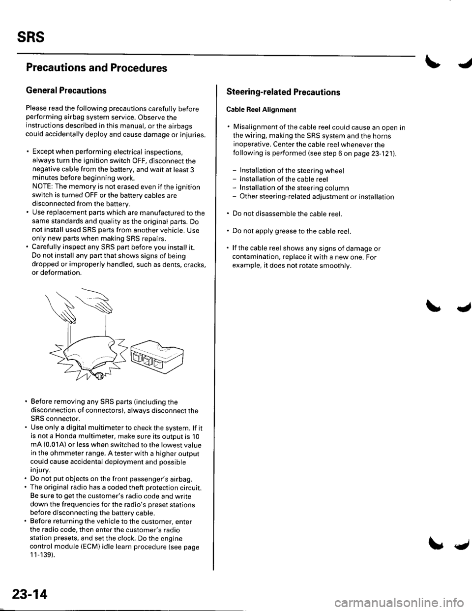
. Before removing any SRS parts (including the
disconnection of connectors), always disconnect the
SRS connector.. Use only a digital multimeter to check the system. lf itis not a Honda multimeter, make sure its outout is 10mA (0.01A) or less when switched to the lowest value
in the ohmmeter range. A tester with a higher output
could cause accidental deployment and possible
injury.. Do not put objects on the front passenger's airbag.. The original radio has a coded theft protection circuit.
Be sure to get the customer's radio code and write
down the frequencies for the radio's preset stations
before disconnecting the battery cable.. Before returning the vehicle to the customer, enter
the radio code. then enter the customer's radio
station presets, and set the clock. Do the engine
control module (ECM) idle learn procedure (see page
11-139).
23-14
c
Steering-related Plecautions
Cable Reel Alignment
. Misalignment of the cable reel could cause an open in
the wiring, making the SRS system and the horns
inoperative. Center the cable reel whenever the
following is performed (see step 6 on page 23-121).
- Installation of the steering wheel- Installation of the cable reel- Installation ofthe steering column- Other steering-related adjustment or installation
. Do not disassemble the cable reel.
. Do not apply grease to the cable reel.
. lf the cable reel shows any signs of damage or
contamination. replace it with a new one. For
example, it does not rotate smoothly.
Page 1025 of 1139
sRs
Precautions and Procedures (cont'dl
Spring-loaded Lock Connector
Some SRS system connectors have a spring-loaded
lock.
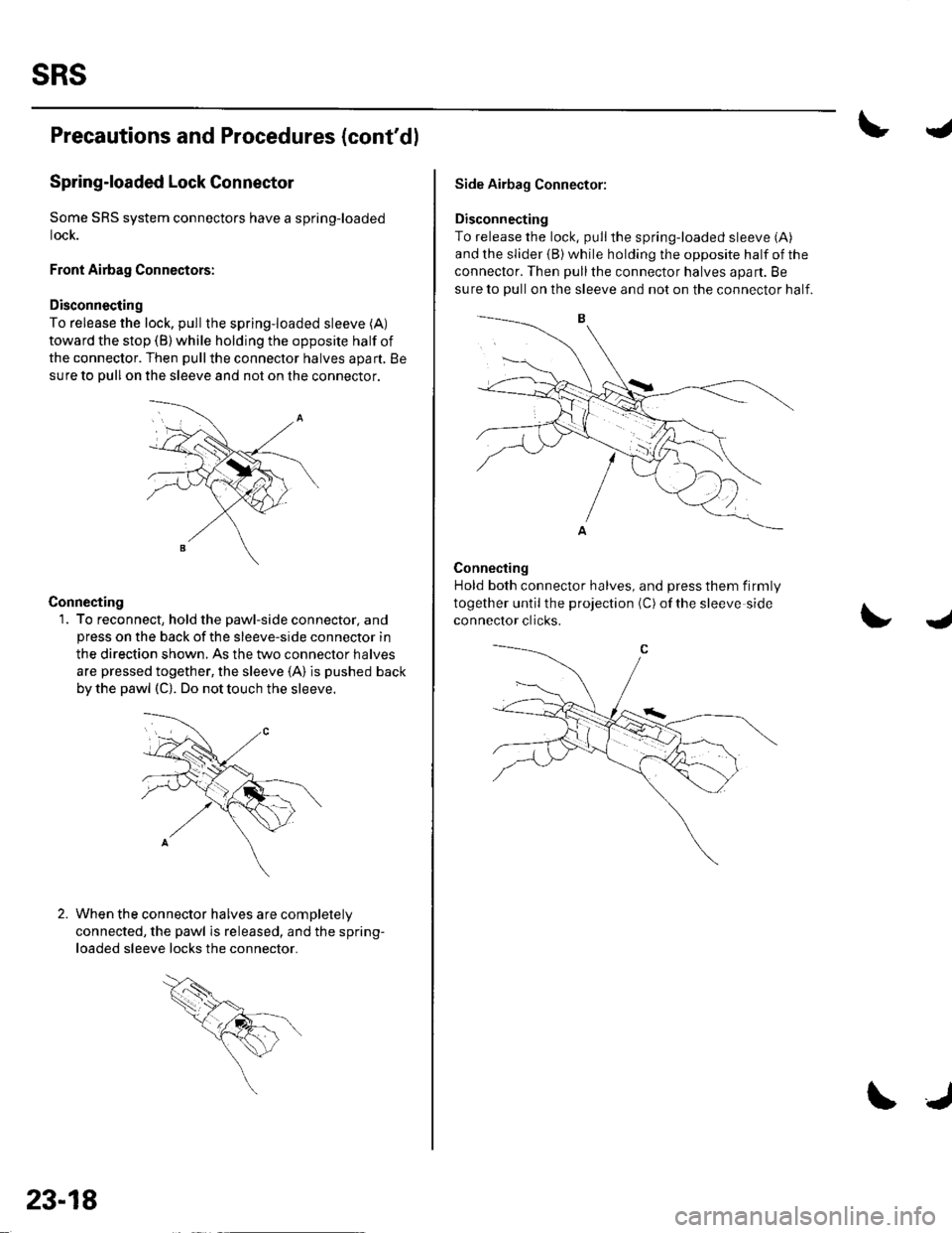
Front Airbag Connectors:
Disconnecting
To release the lock. pullthe spring-loaded sleeve (A)
toward the stop (B) while holding the opposite half of
the connector. Then pullthe connector halves apart, Be
sure to pull on the sleeve and not on lhe connector.
Connecting
1. To reconnect, hold the pawl-side connector, andpress on the back of the sleeve-side connector in
the direction shown. As the two connector halves
are pressed together, the sleeve (A) is pushed back
by the pawl (C). Do not touch the sleeve.
When the connector halves are completelV
connected, the pawl is released, and the spring-
loaded sleeve locks the connector.
23-18
\J
Side Airbag Connector:
Disconnecting
To release the lock, pullthe spring-loaded sleeve (A)
and the slider {B) while holding the opposite half of the
connector. Then pullthe connector halves apart. Be
sure to pull on the sleeve and not on the connector half.
Connecting
Hold both connector halves, and press them firmly
together until the projection (C) of the sleeve side
connector clicks.J
Page 1026 of 1139
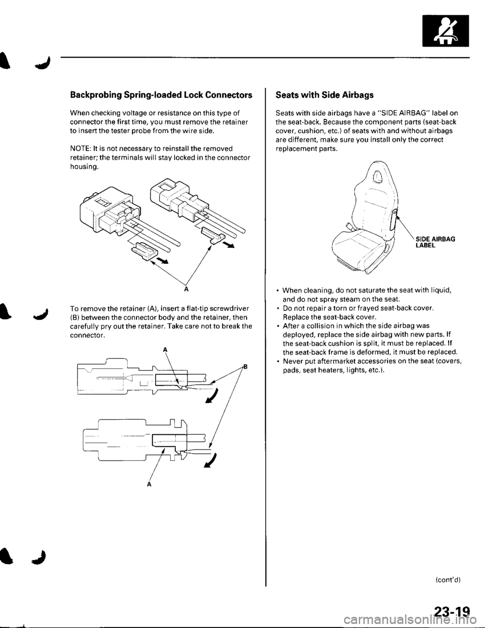
Backprobing Spring-loaded Lock Connectors
When checking voltage or resistance on this type of
connector the first time, you must remove the retainer
to insert the tester orobe from the wire side.
NOTE: lt is not necessary to reinstall the removed
retainer;the terminals will stay locked in the connector
housrno.
A
To remove the retainer (A), insert a flat-tip screwdriver
(B) between the connector body and the retainer, then
carefully pry out the retainer. Take care not to break the
connector.
Seats with Side Airbags
Seats with side airbags have a "SIDE AIRBAG" label on
the seat-back. Because the component pans (seat-back
cover, cushion, etc.) of seats with and without airbags
are different, make sure you install only the correct
replacement parts.
When cleaning, do notsaturatethe seatwith liquid,
and do not sDrav steam on the seal
Do not reoalr a torn or fraved seat-back cover.
ReDlace the seat-back cover.
After a collision in which the side airbag was
deployed, replace the side airbag with new parts. lf
the seat-back cushion is split, it must be replaced. lf
the seat-back frame is deformed, it must be replaced.
Never put aftermarket accessories on the seat {covers,
pads, seat heaters, lights, etc.).
(cont'd)
23-19
Page 1030 of 1139
General Troubleshooting Information
DTC (Diagnostic Trouble Codesl
The self-diagnostic function of the SRS system allows it
to locate the causes of system problems and then store
this information in memory. For easier troubleshooting,
this data can be retrieved via a data link circuit.
. When you turn the ignition switch ON (ll), the SRS
indicator will come on. lf it goes off after 6 seconds,
the system is normal.. lf there is an abnormality, the svstem locates and
defines the problem, stores this information in
memory, and turns the SRS indicator on. The data
will remain in the memory even when the ignition
switch is turned off or if the battery is disconnected.. When you connect the Honda PG lM Tester to the 16P
data link connector (DLC)to short the SCS terminal,
and turn the ignition switch ON (ll). the SRS indicator
will indicate the diagnostic trouble code (DTC) by the
number of blinks.. When you connect the Honda PGM Tester to the 16P
data link Connector (DLC), you can retrieve the DTC in
the Honda Systems "SRS" menu.. After reading and recording the DTC, proceed with
the troubleshooting procedure for th is code.
Precautions. Use only a digital multimeter to check the system. lf
it's not a Honda multimeter, make sure its output is
10 mA (0.01A) or less when switched to the smallest
value in the ohmmeter range, A tester with a higher
output could damage the airbag circuit or cause
accidental airbag deployment and possible injury.. Whenever the ignition switch is ON (ll), or has been
turned OFF for less than 3 minutes, be careful not to
bump the SRS uniU the airbags could accidentally
deploy and cause damage or injuries.. Before you remove the SRS harness, disconnect the
driver's airbag connector. the front passenger's
airbag connector, both side airbag connectors, both
seat belt buckle tensioner connectors, and both seat
belt tensioner connectors.. Make sure the battery is sufficiently charged. lf the
battery is dead or low, measuring values won't be
correct.. Do not touch a tester probe to the terminals in the
SRS unit or harness connectors, and do not connect
the terminals with a jumper wire. Use only the
backprobe set and the Honda PGM Tester. Backprobe
spring loaded lock type connectors correctly.
Reading the DTC
When the SRS indicator is on, read the DTC using either
of the following methods:
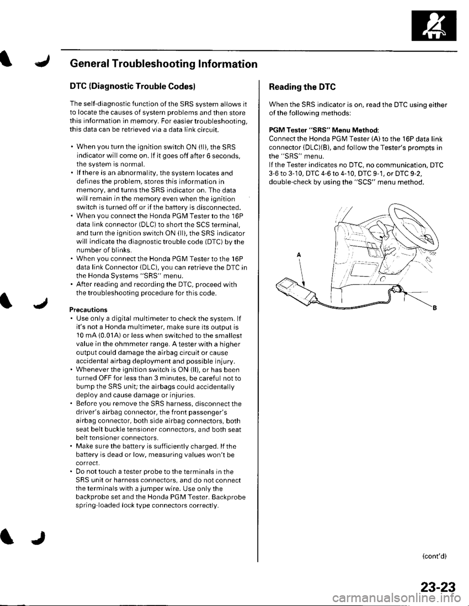
PGM Tester "SRS" Menu Method:
Connect the Honda PGM Tester {A) to the 16P data link
connector {DLC)(B), and follow the Tester's Drompts in
the "SRS" menu.
lf the Tester indicates no DTC, no communication. DTC
3-6 to 3-'10, DTC 4-6 to 4-10, DTC 9-1, or DTC 9-2,
double-check by using the "SCS" menu method.
(cont'd)
23-23
Page 1128 of 1139
)
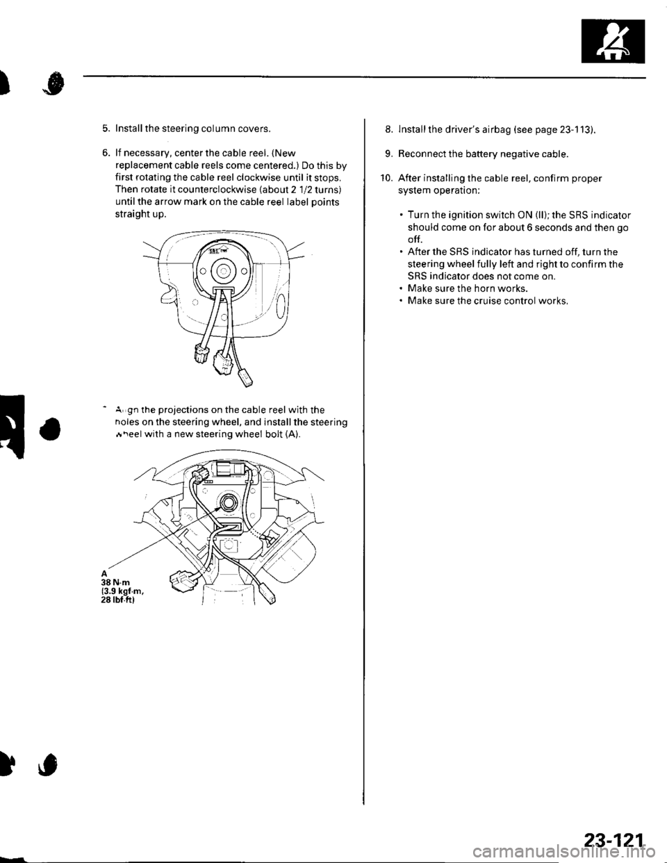
Install the steering column covers.
lf necessary, center the cable reel. {New
replacement cable reels come centered.) Do this by
first rotating the cable reel clockwise until it stops,
Then rotate it counterclockwise labout 2 1 12 lurns)
untilthe arrow mark on the cable reel label Doints
straight up.
- A gn the projections on the cable reel with the
noles on the steering wheel, and installthe steering
Ai\eel with a new steering wheel bolt (A).
)c
23-121
8. lnstallthe driver's airbag (see page 23-113).
9. Reconnect the battery negative cable.
10. After installing the cable reel, confirm proper
syslem operalton:
. Turn the ignition switch ON (ll); the SRS indicator
should come on for about 6 seconds and then go
off.. After the SRS indicator has turned off, turn the
steering wheel fully left and right to confirm the
SRS indicator does not come on.. Make sure the horn works.. Make sure the cruise control works,
Page 1134 of 1139
Service Manual Index
(cont'dl
Brake System Indicator CircuitCircuit DiagramConventional Brake Components..... 19-9TroubleshootingABS/TCS Components .... ....... ...... 19-55
Bulb, GeugeRep|acemenl................ .. ............2263
Bulb, HeadlightReplacement ......................................... 22-A1
Bumper, FrontRemoval/1nsra11ation ............................ 20 85
Bumper, RearRemoval/lnstallation... ... . .....20.86
Combination Light SwilchTesVReplacement ..............................22 80
Connecting Rod BearingsRep|acement...................... .......-....7-8
Connecting Rod Boltsf nspection ....................-.-.-.-.................... 7 -24
Connecting RodsInspection ........,,.,.,...,.,.,.,.,,,,.,,,.,.,.,.,.,.,.,.. 7 5
Connectors(See first page of this Index)
Conventional Brake Component3Component Location Index ................... 19'3Troub1eshootin9 ..................................... 19-4
Cylinder Head AssemblyComponent Location Index ..................... 6-3Inspection ................................................. 6 6Removal ..........&�23Insta11alion .............................................. 6 39
Cylinder Head Cover8emova1 ..............-.-................................. 6-22Installation ..............................................6-41
Cylinder Head, BareInspecton..,.....,.
D
c
Cable ReelReplacement....................................... 23-1 19
CamshaftInspection .......................-...-................... 6-29
Cargo Area LightTesVRep1acement ................................ 22-97
CarpetReplacement.....-...-..... ... ......-.20-55
Ceiling Light-estrReplacement ................................ 22.96
Charging SystemComponent Location Index................... 4-20Circuit Diagram ...................................... 4-21
19-8
CoolantInspection .................. ..... .. 106Replacement................. ... . .. 10 6
Coolant Temperature Gat|geTroub1eshootin9................................... 22 64
Cooling SyslemComponent Location Index................... 10-2
Countershaft BearingsReplacement............... ..................... 13-42
Cowl CoverReplacement............... .. ..... ....20-95
CrankshaftRemoval .................................................. 7 -12
Repair ..................
Inspec(on,,,,,........1 14
Dampers. FrontReplacement................ ..................... 18 20
Oampers, RearRep1acement......................................... 18-34
Dash VentsBemoval/lnstallation .-.......................... 20-64
DashboardBemoval/1nsta11ation ............................ 20-66
Oashboard Center PanelRemoval/1nstaf 1ation ............................ 20 62
Dashboard Lower CoverRemoval/lnstallation ...................... 20-59, 63
Dashboard Under CoverRemoval/lnstallation ............................ 20 60
Diff erential Carrier Bearings, M/TRep1acement,,......,...,...,.,.,,,.,.,,,........,.,. 13-54
Ditferential Oil Seals, M/T8ep1acement......................................... 13-55
Differential Pinion Gears, M/TInspection .,....-,.,,,.,..,.-,.,.........,.,.,,, 13 53
OLC CircuitTroubleshooting ................................ 1 1-109
Door GlassRep1acement.,.,,,,,,,,,,,.,,,,,,,,,,.,.,.,.,.,,,,,,.,, 20-9Adjustment. .. .....................20-11
Door Glass WeathelstripsReplacement .............-.. . . . ..........-......20 10
Door LatchesReplacement ..........-.-.............................. 20-7
Door Lock ActuatorsTest ...................................................... 22-154
Door Lock Knob SwitchesTest -......... . . . - . . . . . . . . ......22-160
Door Lock SwitchesTest ........... ............................ ............. 22-160
Door Outer HandlesRep1acemen1 ........................................... 20-6
3
Child Seat Tether AnchorRemoval/lnstaf lat;on .. ........................ 23 11
CKP (Crankshaft Position) SonsorReplacement....................................... 1 1-116
ClutchComponentLocation 1ndex................... 12-3Rep1acemen1........................................... 12-9
Clutch InteYlock SwitchTest.....-........-...-............. ...---.-.......4-6
Clutch Master CylinderReplacement........................................... 12 5
clutch PedalAdjustment ............................................. 12 4
Clutch Pedal Position SwitchTest.,.,,,,,.,,,.,.,,,,,,.,.,,,,,,,,,.,,,,,.. ......445
lnstallation.................. . ..... .....1-24
Crankshalt Main BearingsReplacement........-.-.................................. 7-6
CrankshaftOil Seal,Transmission End1nstanation .............................................. 7 28
Crankshafl PulleyRemoval/lnstallation -..................-.......... 6-1 1
Cruise Control Actuator
Troubleshooting
Clutch Slave CylindorBeplacemeit...
...................... 4-43
.......4-22
Test
12-1
RepIacement........................................... 4-44
Cruise Control Actuator CableAdjustment ............................................. 4 45
Cruise Control Main SwitchTesVRep1acement .................................. 4 42
Cruise Control Set/Resume/Cancel SwitchTesVRep1acement .................................. 4 42
Cruise Control SystomComponent Localion Inde\................... 4-36Circuit Diagram ....-................................. 4 37
Cruise Control UnitInputTest.............................. .. ...4,40CMP {Camshaft Positionl Senso]Replacement....-...-.............................. 1 1-128
CMP (TDC) SensorsReplacement............-.......................... 1 1 1 14
Page 1135 of 1139
)
Orive BehInspecaron................ 4-26
Door PanelsRemoval/lnstallation -............................. 20-4
Door Sash TrimRep1acement......................................... 20 10
Door StrikersAdiustment ........................................... 20-13
Door Weatherst psBeplacement...........-............................. 20 1 1
EPS Conirol UnitRemoval/1nsta11ation ..................-......... 17-67
EPS Indicator CircuitTroubleshooting ................................... 17 -47
EPS MotorRemoval/lnstallation .-.......................... 17-49
EVAP CanisterRep1acement......................... ......... 11,189
EVAP Control Syst€mComponentLocation Index ..............'11-170
EVAP Two-Wey ValveTest ..........-.............-............................ 11 186
Evaporetor CoreRep1acement........................ . ... 21-42
Evaporator Tomperature SensorReplacement......................................... 21 -37Test..................................... ..........2137
EvaporrtoFHeater UnitReplacement........................................ 21 43
Exhaust ManifoldRemoval/1nsta11ation ................................ I 7
Exhaust Pipe8ep|acement............................................. 9-8
Front SpeakersRep|acement....................................... 22-102
Front SuspensionComponentLocation Index................... 18-3
Fueland EmissionsDescription ........................................... 11-12
Fuel Fill DoorAdjustment ..........-................................ 20 93
Fuel Fill Door OpenetBeplacement........................ . ............ 20.109
Fuel Fill Door Opener CableReplacement....................................... 20- lO7
Fuel FilterReplacement....................................... 1 1-152
Fuel Gauge Sending UnitTest ......................-.-..........-.................. 11'156
Fuel Injection Syslem (PGM"FIlComponent Location 1ndex................. 11-49
Fuel IniectorsRep1acemen1....................................... 1 1 1 1 l
Fuel Lines and HosesInspection .......................................... 1 1'146Removal ....................... . .. . .... 11-149Insta|1ation .......................................... 1 1 150
FuelPipe ProtectolReplacement....................................... 20-104
Fuel Pressure RegulatotReplacement....................................... 1 1-152
Fuel Pulsation DamperReplacemenl................................... 11 154
Fuel PumpReplacement,,,,,.,.,.,,,.,,,,,,,,,,,,.,.,.,,,..,.. 11-153
Fuel Pump CircuitTroubleshooting -.......-....................... 1 1-141
FuelSupply SystemComponent Location lndex .............. 11 140Adjustment................................... 11-144Test........-...-................. ... ............- 11-145
FuelTankBeplacemenl.............. . ..... .. 11 155
Fuel Tank Vapor ControlValveTest ......................-....... ... . . 11-187Replacement,,.,,...,.,,,.,.,,,,... .. .. 11 189
Fuses{See first page ofthis Index)
)
Rep|acement................. ..................... 4 26
Drive Belt Auto-tensionellnspection ............................................... 4 21Rep1acement.................................... ..4-28
Driver's PocketRemoval/lnstallation -........................... 20-60
Driver's TrayRemoval/lnstallation .........................-.- 20-65
DRL {Daytime Running LightslControl Unitlnput Test .................... ........ . . . ......22-16
DTCs(See first page olthis Index)
Dust and Pollen FillerReplacement......................................... 21-39
Dynamic Damper, DriveshaftsReplacement........................................... 16-8
ECT SensorReplacement.,.,,,.,.,,,,,,,,,,,,,,................ 1 1-1 14
El€ctrical Power Steering IEPS)Signal CircuitTroubleshooting ........ ... .. 11-135
EmblemsReplacement......................-................ 20-100
Engine AssemblyRemova1 .................................................... 5 2Installation ............._.................................. 5-9
Engine Block AssemblyComponent Location Inder ..................... 7.3
Engine Block, BareInspect|onRepair
Fan ControlsComponent Location Index................. 10'l 1Circuit Diagram .. ..... . .. . .................. 10 13
Fender Fairing, FrontReplacement...-................................... 20-103
Final Driven Gear. M/TReplacement.... . . ................................ 13-53
FrameRepair Chan............ ... ....................... 20 11 4
Frame StiffenelReplacement......-................................ 20- J'13
Front ConsoleRemoval/lnstallation ............................ 20 5lDisassembJy/Reassemb|y ................... 20 58
Front DoorsComponent Location Index................... 20-2Adiustment ........................................... 20.12
Front Driveshaft AssemblyInspeclion .................... ... ....16 3Remova1...................-...... ... .....16-3Disassembly ............................... .....165Resassemb|y ................................-......... 16-9Insta11arion ........................ ...... ............ l6 17
Front lmpact SensorsRep1acement............................ ...23 125
................7-15................1 11
)
Entry Light Control SystemComponent Location Index ...............-. 22-89Circuit Dia9ram .................................... 22 90
EPS ComponentsComponent Location 1ndex..........-...... 17-!7Description ........................ ...... ..17-24Circuit Diagram11 26(cont'd)
Page 1136 of 1139
Service Manual Index
(cont'dl
Gauge A3semblyReplacement......................................... 22 64
Gaug€sComponent Location Index ..........-...... 22 54How-to lnformation ........................22-56Circuit Diagram22-54
Heater Valve CableAdjustment ...................... .................... ?1-46
High Mount Brake Light8ep|acement......................................... 22 82
Hood
lmmobilizer SystemComponent Location In dex .............. 22-162
\
G
Description
Genoral Information(See seclion 1)
Glove BoxRemoval/1nsta11ation .......................-.... 20-63
GrilleReplacement...........-............................. 20-94
Hood lnsulatorReplacement......................................... 20-89
Hood LatchRep1acement................... ..........20 108
Hood Opener CableComponentLocation Index ..............20 105Replacement ................ . . ........... .....20 106
Hood SealBeplacement.-...........................-........... 20-88
HornTesVReplacement . . ................ ...... 22-122
CircuitDiagram ...........................22-164Troubleshooting ............................ 22,165
Inner Fender, FronlRepf acemenl....................................... 20-102
Inside Rearview MirrorReplacement..........-.............................. 20 16
Instrument PanelRemoval/1nsta11ation................. ....... 20-59
Intake Air Bypass ControlThermal ValveTesr................................ ..... ..11-161
Intake Air SystemComponent Location Index ...-.-........ 11-159
Intake ManitoldRemoval/1nsta11ation ................................ I 2
lntermediate Shaft AssemblyRemova1 ................-.-...-......................... 16-19Disassemb|y................... ... ......-.... 16,20Resassemb|y ........................................ 16 22Installation .........-...-.............................. 16-24
Keyless Entry Transmitter
Adjuslment
H
Adiustment .......
Hatch Handle
Horn SwitchTest ............-........
HornsComponent Location IndexCirc!it Diagram
H02S. SecondaryReplacement
..............22-120Replacement
22-122
22 12120-110
20-'110Hatch LatchReplacement$
K
Hatch Latch Switch
.... 11 113
HubsReplacement. ... .................................. 1A 26Test
Test
Replacement
Hatch Support StrutsBeplacement.....
Hatch WeatherstrioReplacement....
Hazard Warning Switchtest
ldle ControlSystemComponentLocation Index .............. 11-129Inspection,.,.........-.......,.,.,,,,,,.,,,.,.,..... 1'l 138
lgnition CoillslBemoval/lnstallation ...............-.............. 4 18
22-161Test ...................................................... 22 161
Keyless Entry/Security Alarm SystemComponenl Location Index .............. 22 150Circuil Diagram ................. . .............. 22 151
Keyless Receiver Unitlnput Test ............................................ 22-153
Knock SensorReplacement......-................................ 1 1 115
KnucklesReplacementFront Suspensron ............................. 18-1 1Rear Suspension ........ .................-... 18-28
Repair ...............
H.tch Lock Actuator22-159
Hatch Lock CylinderRep|acement....................................... 20,111
Hatch SpoilerIAT {lntake Air Temperature} SensorReplacement.,.........-...'11 115
20-91
20-92
.................... 22_88lgnition Key LightTest,,.,,,,.,...,......-.
H6adlightAdjustmentlgnition Key Switch
....................... 22-91
....................... 22-91..22-78TestReQ\ace$entlgnition SwitchTest .,,,.,.,.,,,,.,.,.......22-53License Plate LightReplacement...........-... - ... .....22-83
License TrimReplacement..................-...-..........-....... 20-98
Lights, ExteriorComponent Localion Index.................22 68
Lights,InteriorComponent Location Index................. 22-94CircuitDiagram .. .. ...... .... 22-95
HcadlightsCircuit Diagram .............................. 22-71, 72
HeadlinerRemoval/lnstallalion ............................ 20-54
Heater ControlPanelRemoval/1nsta11ation ............................ 21-38
Heater Control Power and Ground CircuitsTroubfeshooting......... .......................21-27
lgnition SystemComponent Location Index ................... 4-15CircuitDia9ram .................................... 4'161nspection ............................................... 4-17
lmmobilizer Control Unit-Receiver
J
22-161
Page 1138 of 1139
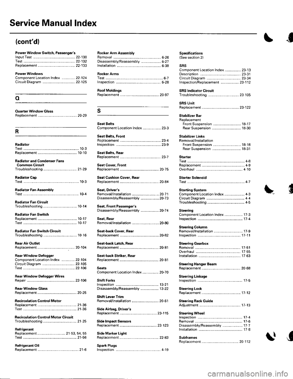
Service Manual lndex
(cont'dl
Power Window Switch, Passenger'slnput Test .............-......
Replacement...,-.-.-...,..
Radialor Cap
Rocker Arm AssemblyRemovalD;sassembly/Reassembly
Specifications6-26 (See section 2)22-13022 13222-133..................... 6-27
ComponentLocation Index ..............22 124Circuit Dia9ram .................. ............... 22 125
Ouaner Window Glass8ep1acement ......................................... 20-29
lnstallation6-38
Rocker ArmsTestInspecton6-28
Roof MoldingsReplacement
Seat BeltsComponent Location Index ................... 23-3
Seat 8ehs, FrontReplacementrnspec!on
sRsComponent Location Index ................. 23-13Description ....................................... 23-31Circuit D;agram ... .... ...........2334lnspection/Replacemenl ................... 23 1 126-7
SRS lndicator CircuilTroubleshooting
Startel
Stabilizer BarReplacementFront SuspensionRear Suspension
Stabilizer LinksRemoval/lnstallationFront SuspensionRear Suspension
23 105oSRS UnitReplacement..-.................................... 23-122s
R
1A-1718-30
18 1818-31RadiatorTest......23-9
23-1Replacement ...........
Radiator and Condenser FansCommon CircuitTroubleshooling......... ..... .........21 29
10-310-10Seat Behs, RearReplacement
Seat Cover, FrontReplacement
Seat Cushion Cover, R6ar10-3Replacement
ReplacementTest
Test
20-75
20-84
Overhaul
Starter SolenoidTest..-.-...4-7
Radiator Fan AssemblyTestSeat, Driver'sRemovaf/lnstaf lation ............................ 20 1 1Disassembly/Reassemb1y ................... 20-73
Sedt, Faont Passenger'sDisassembly/Reassemb1y ................... 20-74
Seat, RearRemoval/lnstallation ............................ 20-80
Seat-back Cover, Reer
Starting SystemComponent Location Index...............-..... 4-3CircuitDia9ram ........................................ 4 4
\'{........................ r0-4
Radiator Fan CircuitTroubleshooting
Radiator Fan SwhchReplacementTest
Radiator Fan Switch CircuitTroubleshooting
Rear Air OutletReplacement
Circuil DiagramTest
Rear Window D€rogger WiresRepair
RearWindow GlassReplacement
Troubleshooting10-14
10-1710-17
10 16
17 -3
11-4
17-9
SteeringComponent Location Index................-..Inspectaon ...................
Steering ColumnRemoval/lnstallationReplacementInspection11 11
17-5117 5517 63
20 68
Seat-back Latch, ReaI2Q-104Replacement
Seat-back Striker. RearReplacement
Steering GearboxRemovalOverhaulRear Window DefoggerComponentLocalion Index ..............22 104lnstallation
Steering Hanger BeamReplacement
Steering LinkageInspefiron
Steering LockReplacement
Steering Rack GuideAdiustment
22-10522 106
22-106
SeatsComponent Location Index....-............ 20-70
Shift ForksInspectton13,21
20-25
2l-3621 36
21 25
Disassembly/Reassembly ................... 13-22
Shitt Lever TrimRemoval/lnstallation ............................ 20 61
.....11-12
SecirculationReplacementControl Motor17-13Test.....
Recirculation Control Motor CircuitTroubleshooting
Side Airbag, Drivel'sReplacement
Side lmpact SensorsReplacement
Spark Plugs
23-115
23 123
Side Marker LightRep1acement......................................... 22-A3
17417-6Disassembly/Reassembly ..................... 17 71nsta11ation .............................................. 17-8
SublramesReplacement
Removal
RefrigerantReplacement ..-.-.-...................... 21 53, 54, 55Test ........................................................ 21-56
Retrigerant OilReplacement...............................-........... 21-6. .._..4_19
20 112