lock HONDA CIVIC 2002 7.G Workshop Manual
[x] Cancel search | Manufacturer: HONDA, Model Year: 2002, Model line: CIVIC, Model: HONDA CIVIC 2002 7.GPages: 1139, PDF Size: 28.19 MB
Page 745 of 1139
7.
Tighten each bolt and nut securely.
Check that the hatch opens properly and locks
securery.
Reinstall the support struts securely.
Reinstall all remaining removed parts.
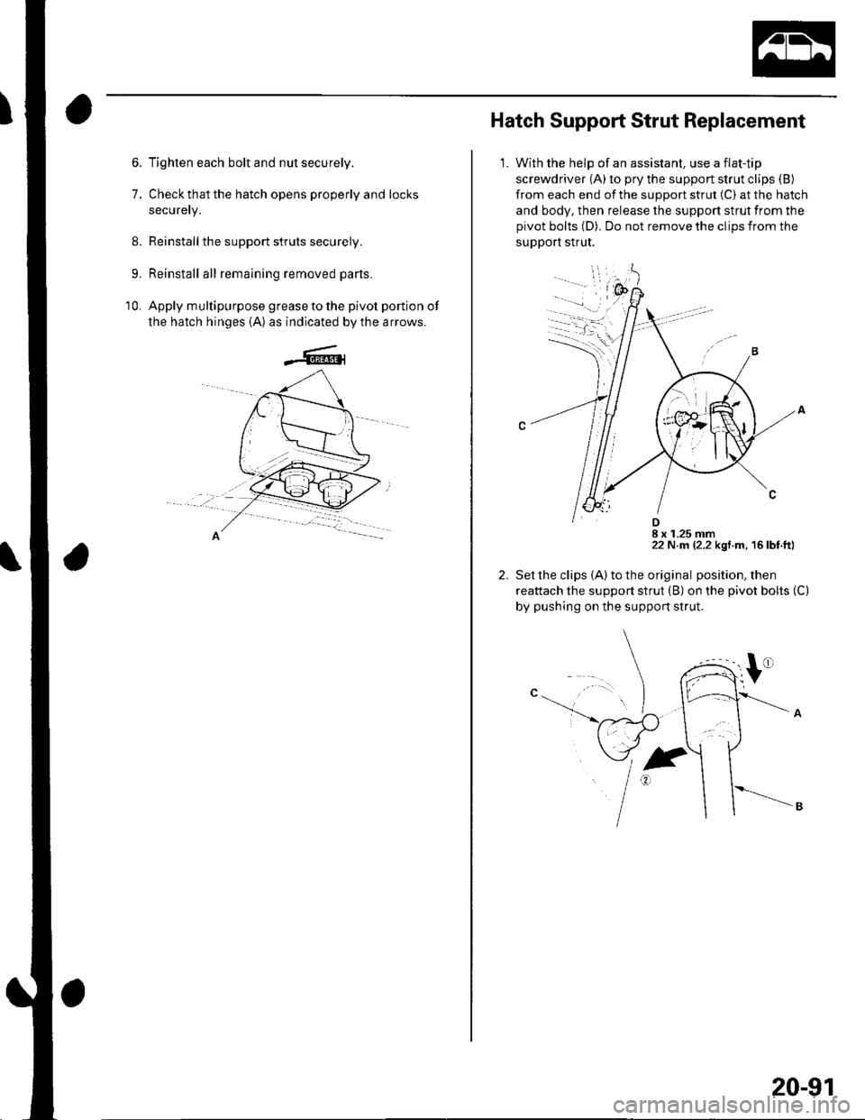
Apply multipurpose grease to the pivot portion of
the hatch hinges {A) as indicated by the arrows.
9.
10.
Hatch Support Strut Replacement
1.With the help of an assistant, use a flat-tip
screwdriver (A)to pry the support strut clips (B)
from each end of the support strut (C) at the hatch
and body, then release the support strut from the
pivot bolts (D). Do not remove the clips from the
support strut.
Set the clips (A) to the original position, then
reattach the support strut (B) on the pivot bolts (C)
by pushing on the support strut.
2.
D8 x 1.25 mm22 N.m (2.2 kgf.m, 16 lbf ft)
20-91
Page 747 of 1139
Fuel Fill Door
Adjustment
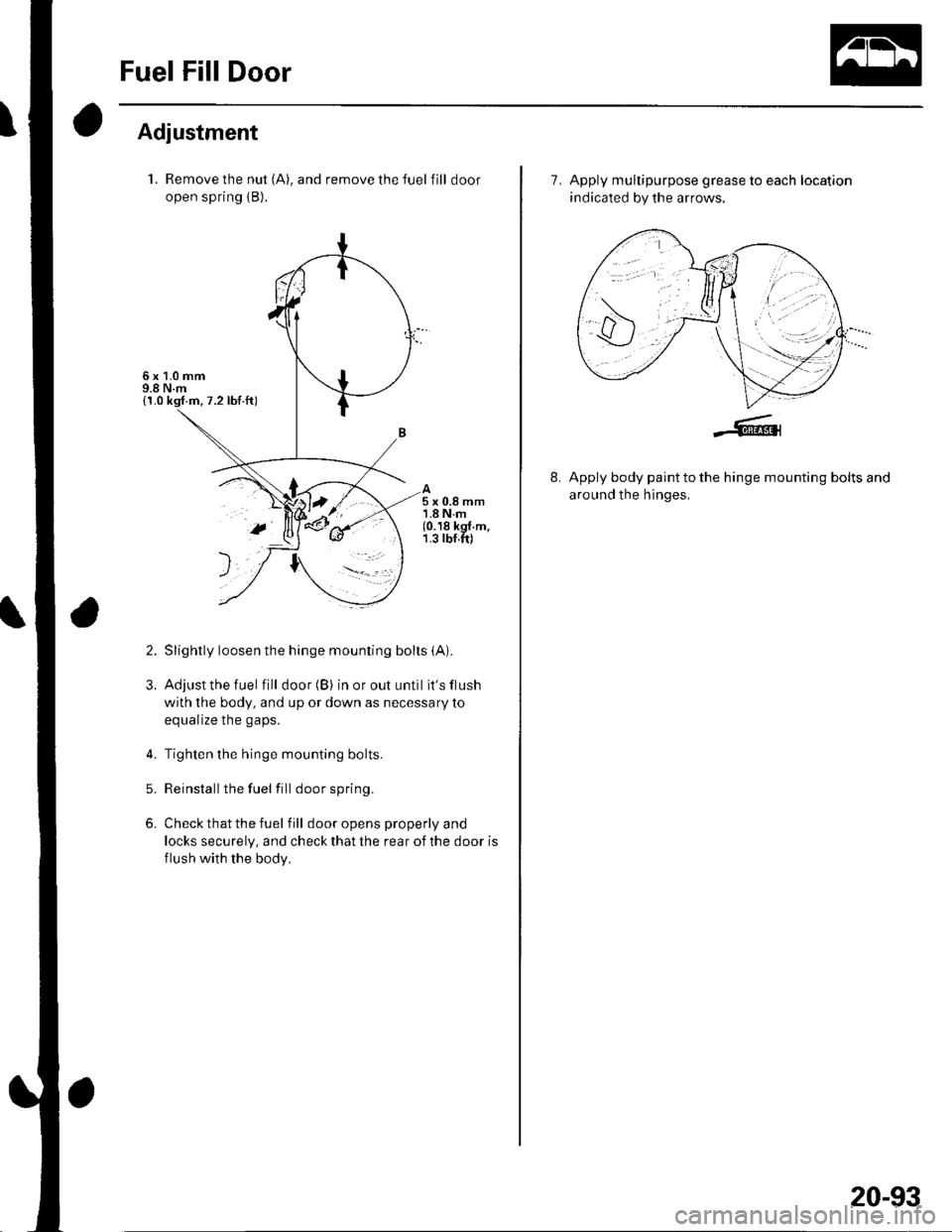
1. Remove the nut (A), and remove the fuel fill door
open spring {B).
Slightly loosen the hinge mounting bolts (A).
Adjust the fuel fill door (B) in or out until it's flush
with the body, and up or down as necessary toa^rr.li7a tha n.nc
Tighten the hinge mounting bolts.
Reinstallthe fuel fill door spring.
Check that the fuel f ill door opens properly and
locks securely, and check that the rear of the door is
flush with the body.
5x0.8mm1.8Nm(0.18 kgf.m,1.3 rbf.ft)
2.
3.
5.
6.
>t=- r'
7. Apply multipurpose grease to each location
indicated by the arrows.
8.Apply body paint to the hinge mounting bolts and
around the hinges,
20-93
Page 752 of 1139
Exterior Trim
\
Rear License Trim Replacement
NOTE: Put on gloves to protect your hands.
1. Remove the hatch lower trim panel (see page 20-
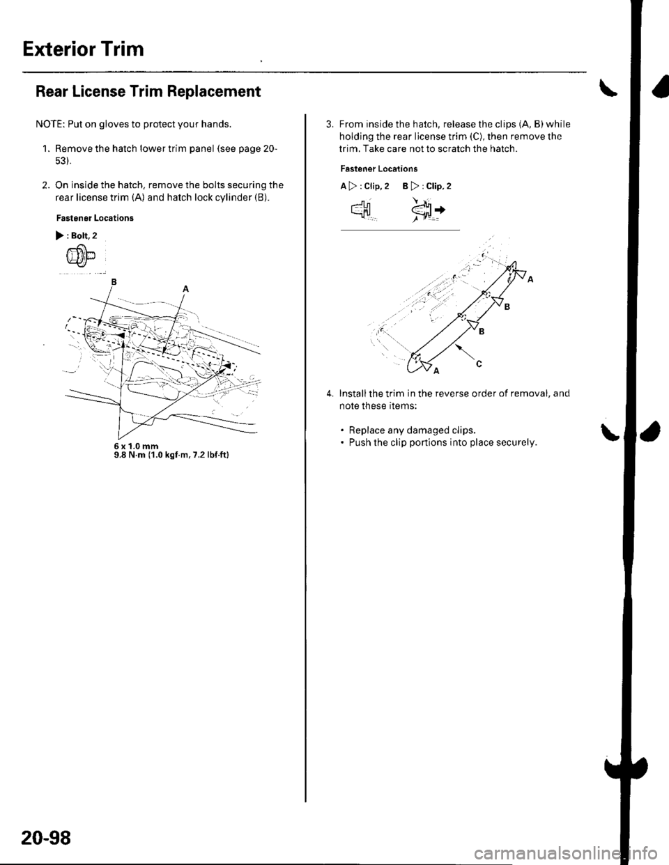
2. On inside the hatch. remove the bolts securing the
rear license trim (A) and hatch lock cylinder (B).
Fastener Locations
> : Bolt,2
-)
6x1.0mm9.8 N.m (1.0 kgf.m,7.2lbf.ftl
20-98
3. From inside the hatch, release the clips (A, B)while
holding the rear license trim (C), then remove lhe
trim, Take care not to scratch the hatch.
Fastener Locations
A>:Clip,2 B>:Clip.2
\!-
cHl €:t+
Installthe trim in the reverse order of removal, and
note these rtems:
. Replace any damaged clips.. Push the clip portions into place securely.
4.
Page 759 of 1139
Openers
Component Location Index
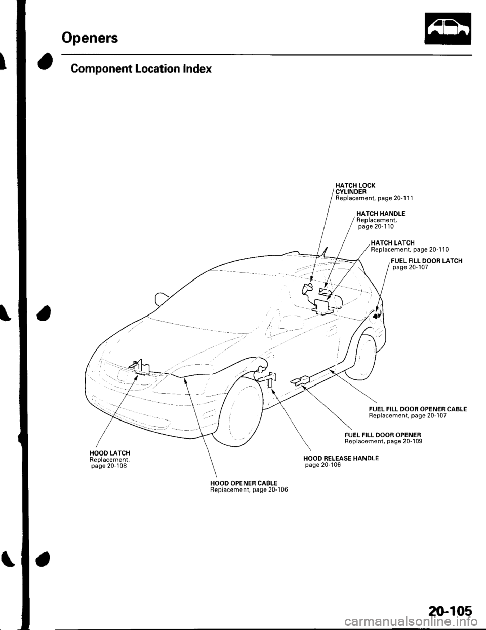
HATCH LOCKCYLINDERReplacement, page 20-1'l 1
HATCH HANDLEReplacement,page 20-110
FUEL FILL DOOR OPENERReplacement, page 20-109
HATCH LATCHReplacement, page 20'1 10
FUEL FILL DOOR LATCHpage 20-107
FUEL FILL DOOR OPENEB CABLEReplacement, page 20-107
I{OOD RELEASE HANDLEpage 20-'106
HOOD OPENER CABLEReplacement, page 20-106
z)-105
Page 762 of 1139
Openers
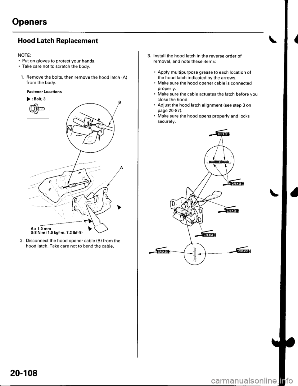
Hood Latch Replacement
NOTE:. Put on gloves to protect your hands.. Take care not to scratch the body.
1. Remove the bolts, then remove the hood latch (A)
from the body.
Fastener Locations
> i Bolt, 3
Disconnect the hood opener cable (B) from the
hood latch. Take care not to bend the cable.
--------------'6x1.0mm9.8 N.m (1.0 kgf.m, 7.2lbf.ft)
20-108
Installthe hood latch in the reverse order of
removal, and note these items:
. Apply multipurpose grease to each location of
the hood latch indicated by the arrows.. Make sure the hood opener cable is connected
properly.
. Make sure the cable actuates the latch before you
close the hood,. Adjustthe hood latch alignment (see step 3 onpage 20-87).. Make sure the hood opens properly and locks
securely.
Page 763 of 1139
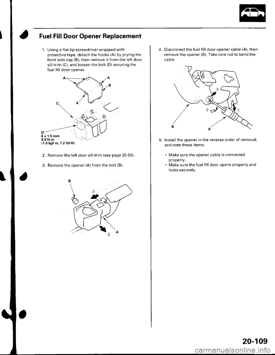
Fuel Fill Door Opener Replacement
1.Using a flat-tip screwdriver wrapped with
protective tape, detach the hooks (A) by prying the
front side cap (B), then remove it from the left door
silltrim (C), and loosen the bolt (D) securing the
fuel fill door opener.
6x1.0mm9.8 N.m11.0 kgf m,7.2 lbf.ft)
Remove the left door sill trim (see page 20-50i.
Remove the opener (Alfrom the bolt {B).
2.
3.
4. Disconnect the fuel fill door opener cable (A), then
remove the opener iB). Take care not to bend the
ca o te.
Installthe opener in the reverse order of removal,
and note these items:
5.
lMake sure the opener cable is connected
properly.
lvlake sure the fuel fill door opens properly and
locks securely.
20-109
Page 764 of 1139
Openers
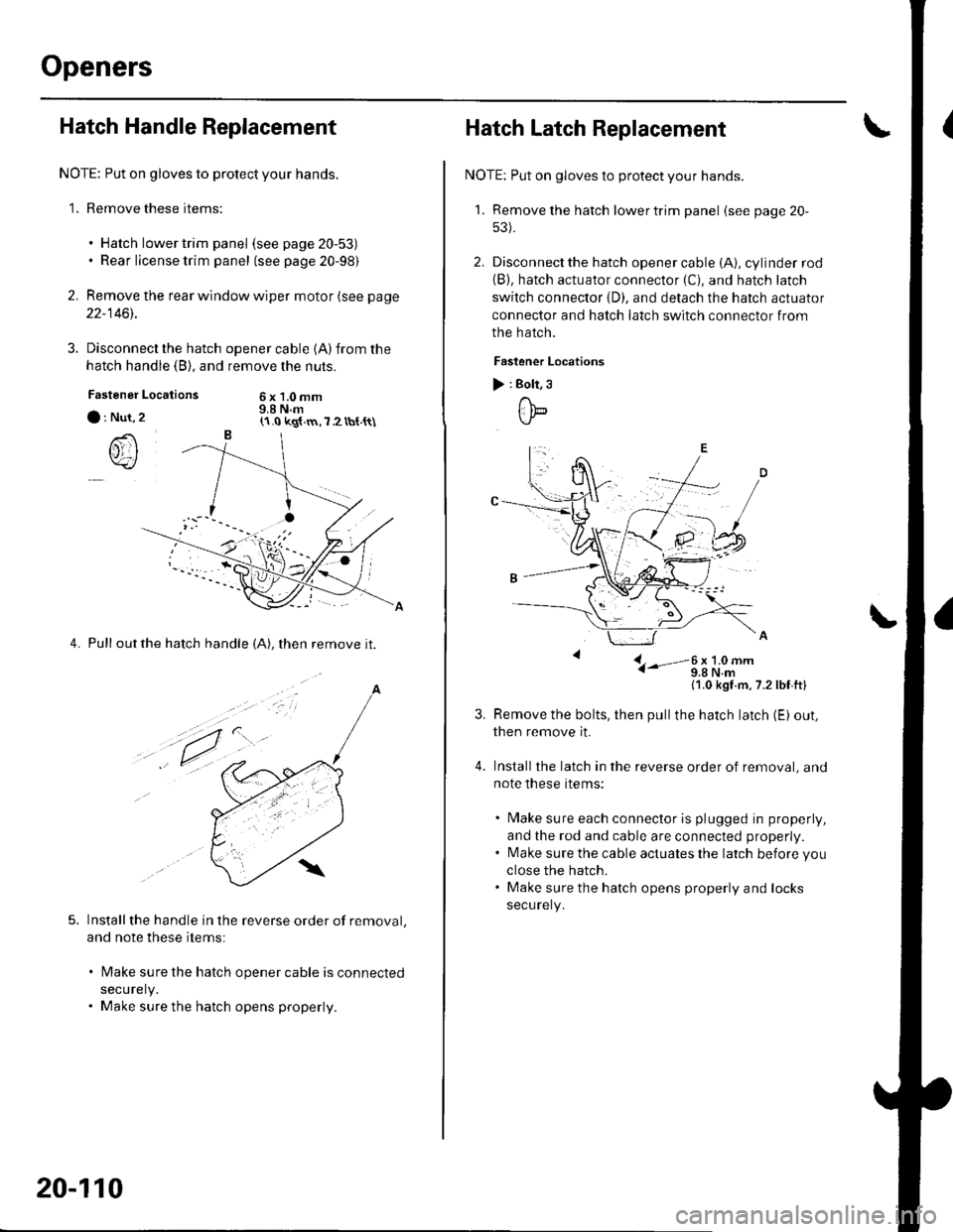
Hatch Handle Replacement
NOTE: Put on gloves to protect your hands.
1. Remove these items:
. Hatch lower trim panel (see page 20-53). Rear license trim panel (see page 20-98)
2. Remove the rear window wiper motor (see page
22-1461.
3. Disconnect the hatch
hatch handle (B), and
Locations
opener cable 1A)from the
remove the nuts.
6x1.0mm9.8 N.mFastener
a : Nut,
()rI
4. Pull outthe hatch handle (A), then remove it.
Installthe handle in the reverse order of removal.
and note these items:
lMake sure the hatch opener cable is connected
securely.
Make sure the hatch opens properly.
(1.0 kg{.m,7 2 tbt.{t\
a
,t.
20-110
Hatch Latch Replacement
NOTE: Put on gloves to protect your hands.
'1. Remove the hatch lowertrim panel (see page 20-
53).
2. Disconnect the hatch opener cable (A), cylinder rod(B). hatch actuator connector (C). and hatch latch
switch connector {D). and detach the hatch actuator
connector and hatch latch switch connector from
the hatch.
Faslener Locations
) : Bolt, 3
ttb
L- i-'-3;li9#-
11,0 kgt m,7.2lbf ftl
Remove the bolts, then pullthe hatch latch (E) out,
then remove it.
Installthe latch in the reverse order of removal, and
note these items:
. Make sure each connector is plugged in properly,
and the rod and cable are connected properly.. l\4ake sure the cable actuates the latch before you
close the hatch.. Make sure the hatch opens properly and locks
securely.
Page 765 of 1139
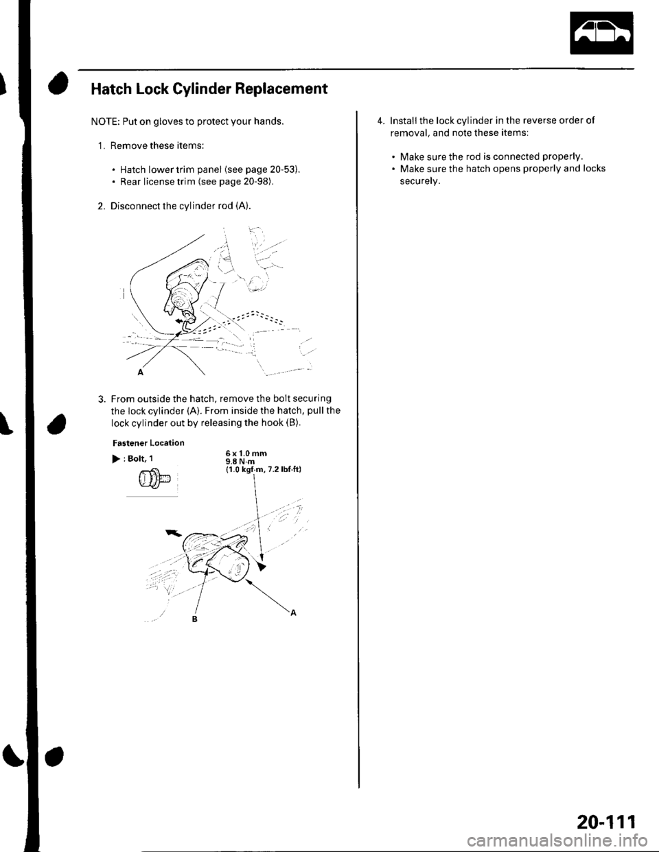
Hatch Lock Cylinder Replacement
NOTE; Put on gloves to protect your hands.
'1. Remove these items:
. Hatch lower trim panel (see page 20-53).. Rear license trim (see page 20-98).
2. Disconnect the cylinder rod (A)
-..
From outside the hatch, remove the bolt securing
the lock cylinder {A}. From inside the hatch, pull the
lock cylinder out by releasing the hook (B).
Fastener Location
> : Bolt, 1
rS'l-.u-ar
6x 1.0 mm9.8Nm(1.0 kgf m,7.2lbt.ftl
*/t
4. Install the lock cylinder in the reverse order of
removal, and note these items:
. Make sure the rod is connected properly.
. Make sure the hatch opens properly and locks
securely.
20-111
Page 779 of 1139
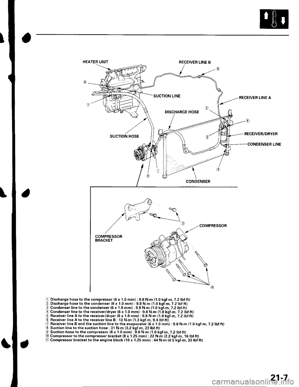
Discharge hose to the compressor {6 x 1.0 mm) : 9.8 N.m {1.0 kgf.m, 7.2 lbl.ft}Discharge hose to the condenser (5 x 1.0 mml : 9.8 N.m {1.0 kgt.m, 7.2 lbf ft)Condenser line to the condenser (6 x 1.0 mm) : 9.8 N.m {1.0 kgf,m, 7.2 lbt.ft}Condenser f ine to the receiver/dryer {6 x 1.0 mm} : 9.8 N.m (1.0 kgt.fi,7.2lbt.ltlReceiver lineAtothe receiver/dryer {6 x 1.0 mm} : 9.8 N.m {1.0 kgf .m. 7.2 lbf .ft}Receiver line A to the receivei line B : 13 N.m (1.3 kgr.m, 9.4 lbf.ft)Receiver line B and the suction line to the evaporator (6 x 1.0 mm) :9.8 N.m 11.0 kgf.m, 7,2 lbf.ft)Suction line to the suction hose : 3l N m {3.2 kgf.m, 23 lbf ftlSuction hose 1o the compressor (6 x 1.0 mm) : 9.8 N.m 11.0 kgf.m. ?.2 lbf.lt)Compressor to the compressor b.acket {8 x 1.25 mm) : 22 N m {2.2 kgt.m, 16 lbf.ft)Compr€ssor bracket to the engine block {10 x 1.25 mm} : ,14 N.m 14.5 kgf.m, 33 lbf.ft)
RECEIVER LINE A
RECEIVER/DRYER
CONDENSER LINE
21-7
Page 809 of 1139
Heating and Air Gonditioning
a
\
Power Transistor Test
1. Disconnect the 4P connector from the power
Iranslslor.
2, Measure the resistance between the No. 1 and
No. 2 terminals of the power transistor. lt should be
about '1.4 1.5 kQ.
. lf the resistance iswithln the specifications, go to
step 3.. lf the resistance is notwithin the specifications,
replace the power transistor.
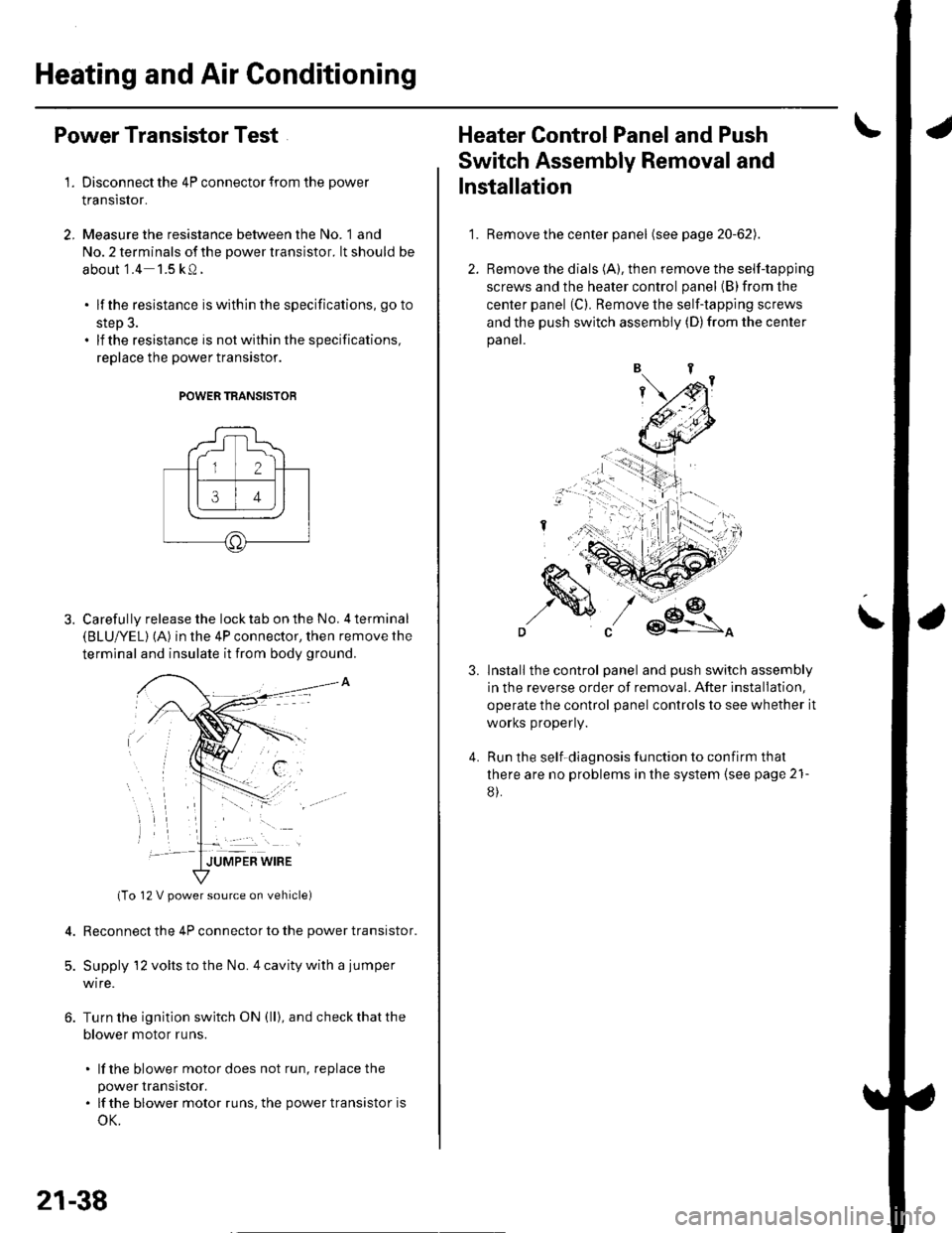
POWER TRANSISTOB
Carefully release the lock tab on the No. 4 terminal(BLUI/EL) (A) in the 4P connector, then remove the
terminal and insulate it from body ground.
(To 12 V power source on vehicle)
Reconnect the 4P connector to the power transistor.
Supply 12 volts to the No. 4 cavity with a jumper
wire.
Turn the ignition switch ON (ll), and check that the
blower motor runs.
. lf the blower motor does not run, replace the
power rranstsror.. lf the blower motor runs,the powertransistoris
oK.
12 V power source on vehicle)
21-38
1.
Heater Control Panel and Push
Switch Assembly Removal and
Installation
Remove the center panel (see page 20-62).
Remove the dials (A), then remove the self-tapping
screws and the heater control panel (B)from the
center panel (Cl. Remove the self-tapping screws
and the push switch assembly (D)from the center
panel.
lnstall the control panel and push switch assembly
in the reverse order of removal. After installation,
operate the control panel controls to see whether it
worKs propeny.
Run the self-diagnosis function to confirm that
there are no problems in the system (see page 21-
8).
3.
4.