lock HONDA CIVIC 2002 7.G Workshop Manual
[x] Cancel search | Manufacturer: HONDA, Model Year: 2002, Model line: CIVIC, Model: HONDA CIVIC 2002 7.GPages: 1139, PDF Size: 28.19 MB
Page 832 of 1139
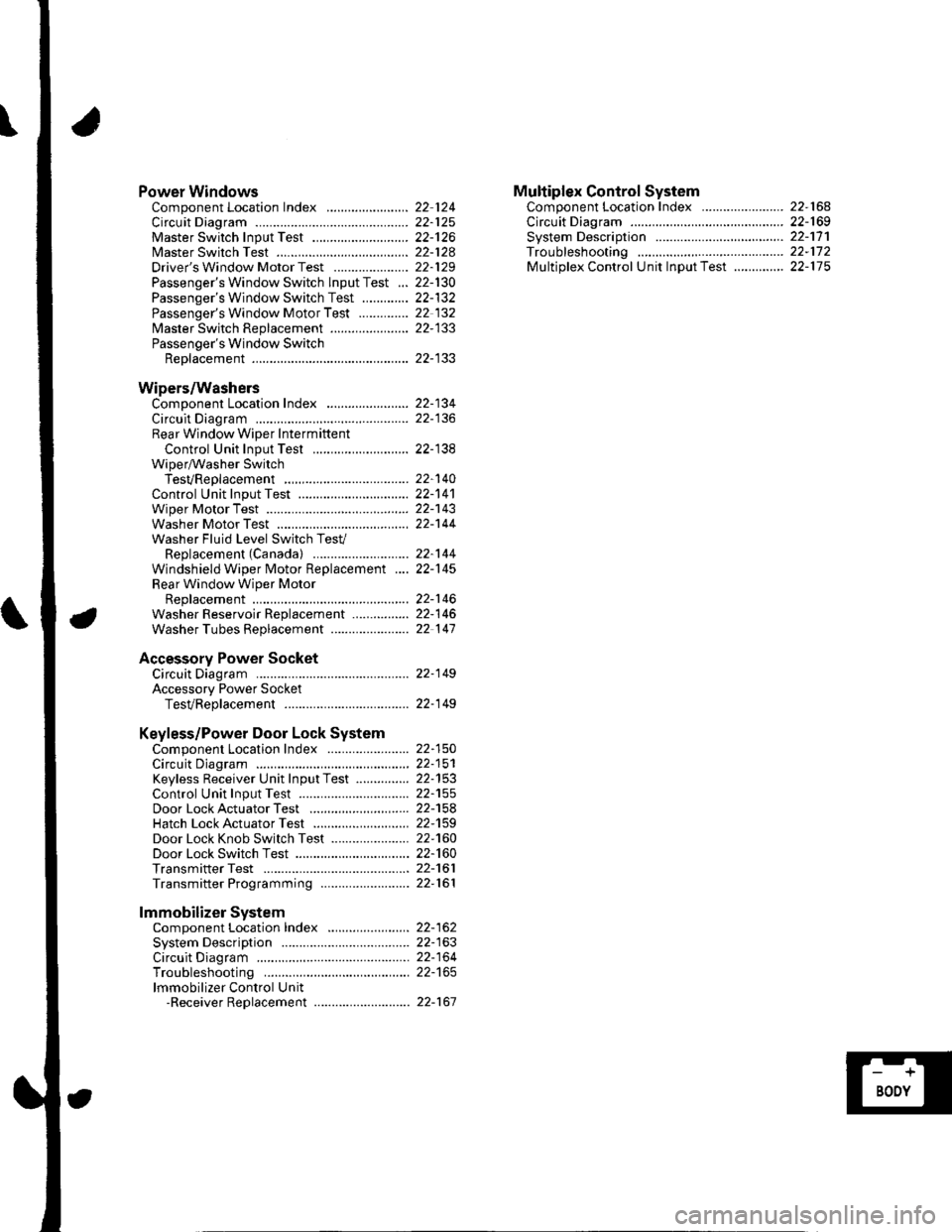
Power WindowsComponent Location Index ..........
circuit Diagram . .. ............... .........:.::::.::::.:Master Switch Input Test ...........................Master Switch TestDriver's Window Motor Test .....................
Passenger's Window Switch lnput Test ...Passenger's Window Switch Test .............
Passenger's Window Motor Test ..............
lMaster Switch Replacement ......................
Passenger's Window SwitchReplacement
Wipers/WashersComponent Location Index .......................
Circuit DiagramRear Window Wiper Intermiftent
Control Unit Input Test ...........................Wiper/Washer SwitchTesVReplacementControl Unit Input Test ...............................Wiper Motor Test
Washer Motor TestWasher Fluid Level Switch TesV
Replacement (Canadal ..........................
Windshield Wiper Motor Replacement ....
Rear Window Wiper MotorReplacementWasher Reservoir Replacement ................
Washer Tubes Beplacement ......................
Accessory Power SocketCircuit Diagram ......... 22-149
Accessory Power Socket
TesVReplacement ................................... 22-1 49
Keyless/Power Door Lock System
Component Location Index ....................... 22-150
Circuit Diagram ......... 22-151Keyless Receiver Unit InputTest ............... 22-153
Control Unit Input Test ............................... 22-155
Door LockActuatorTest .........,.......,..,.,..... 22-158Hatch LockActuatorTest ........................... 22-159
Door Lock Knob Switch Test ...................... 22-160
Door Lock Switch Test ................................ 22-160
Transmitter Test ....... 22-161
Transmitter Programming ......................... 22-161
Multiplex Control SystemComponent Location Index ...........
circuit Diagram ...... ........................::.:..:.::.:
Svstem DescriDtionTroubleshootingMultiolex Control Unit InDut Test .............
22 12422-12522-12622-12822-129
22- t30
22-13222 13222-133
22-133
22-134
22-138
22-14022-14122-14322-144
22-14422-145
22-14622-14622 147
22,16422-16922-17'l22,11222-175
lmmobilizer Systemcomponent Location Index ...........
System Description ....... ............. ..:..:..:.:...
Circuit DiagramTroubleshootinglmmobilizer Control Unit-Receiver Replacement ...........................
22-16222-16322-164
22-167
Page 834 of 1139
General Troubleshooting Information
Tips and Precautions
Bef ore Troubleshooting
1. Check applicable fuses in the appropriate fuse/relay
oox.
2. Check the battery for damage. state of charge, and
clean and tight connections.
. Do not quick-charge a battery unless the battery
ground cable has been disconnected, otherwise
you will damage the alternator diodes.. Do not attempt to crank the engine with the
battery ground cable loosely connected or you
will severely damage the wiring.
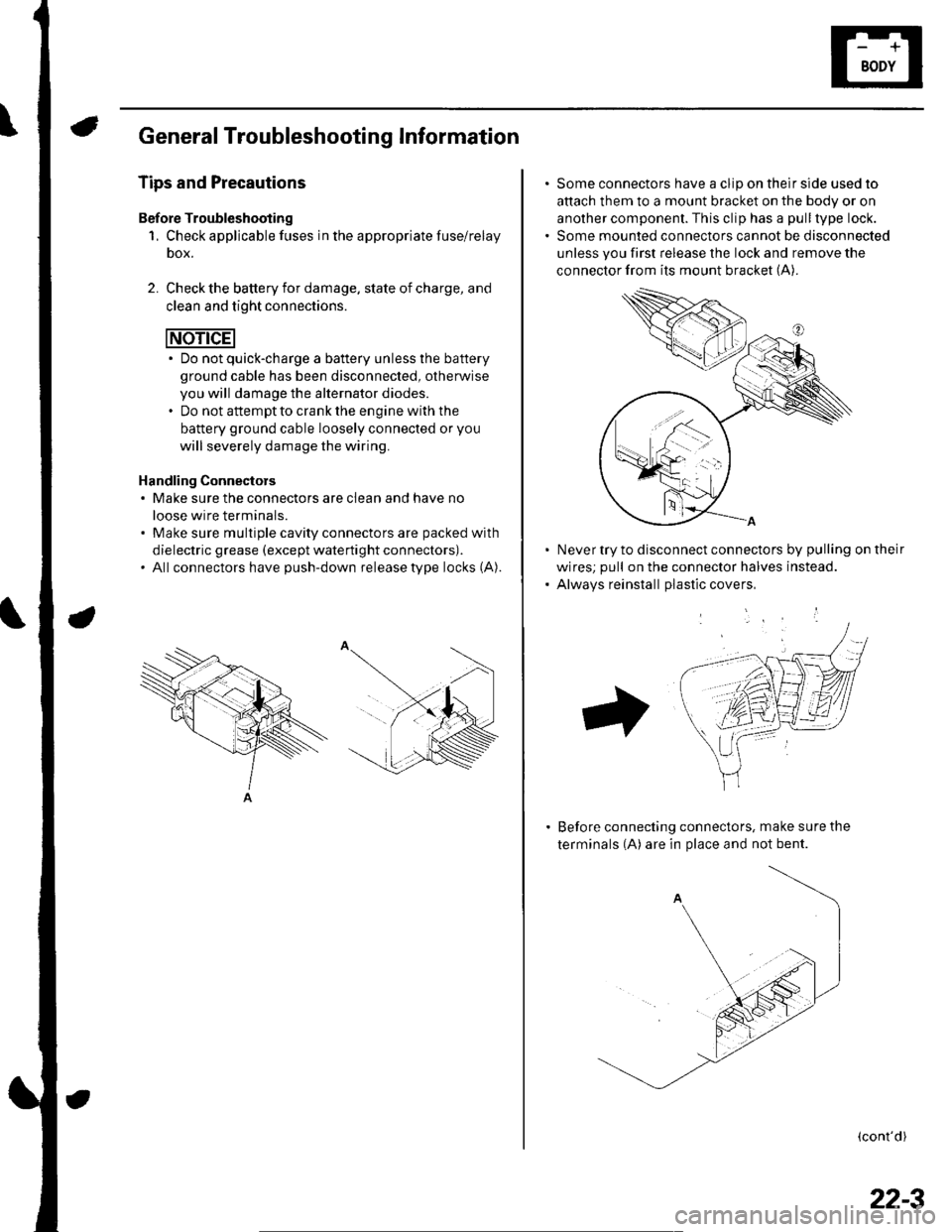
Handling Connectors. Make sure the connectors are clean and have no
loose wire terminals.. Make sure multiple cavity connectors are packed with
dielectric grease (except waterti ght connectors).. All connectors have push-down release type locks (A).
Some connectors have a clip on their side used to
attach them to a mount bracket on the body or on
another component. This clip has a pull type lock.
Some mounted connectors cannot be disconnected
unless you first release the lock and remove the
connector from its mount bracket (A).
Never try to disconnect connectors by pulling on their
wires; pull on the connector halves instead.
Alwavs reinstall Dlastic covers,
Before connecting connectors, make sure the
terminals (A) are in place and not bent.
(cont'd)
22-3
Page 835 of 1139
Body Electrical
General Troubleshooting Information (cont'd)
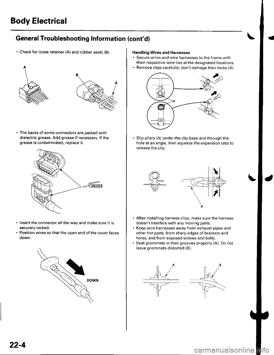
Check for loose retainer (A) and rubber seals (B).
The backs of some connectors are packed with
dielectric grease. Add grease if necessary. lf thegrease is contaminated, replace it.
lnsert the connector all the way and make sure it is
securelv locked.
Position wires so that the open end of the cover faces
oown.
22-4
Handling Wires and Harnesses. Secure wires and wire harnesses to lhe frame with
their respective wire ties at the designated locations.. Remove clips carefully; don't damage their locks (A).
Slip pliers (A) under the clip base and through the
hole at an angle, then squeeze the expansion tabs to
release the clip.
After installing harness clips, make sure the harness
doesn't interfere with any moving pans.
Keep wire harnesses away from exhaust pipes and
other hot parts, from sharp edges of brackets and
holes, and from exposed screws and bolts.
Seat grommets in their grooves properly {A). Do not
leave grommets distorted (B).
lt" /wl/
\--------\tfl r'---'..-
It
J
|,f . ./.ll t/
----E; F.�'l/
I
Page 857 of 1139
Connectors and Harnesses
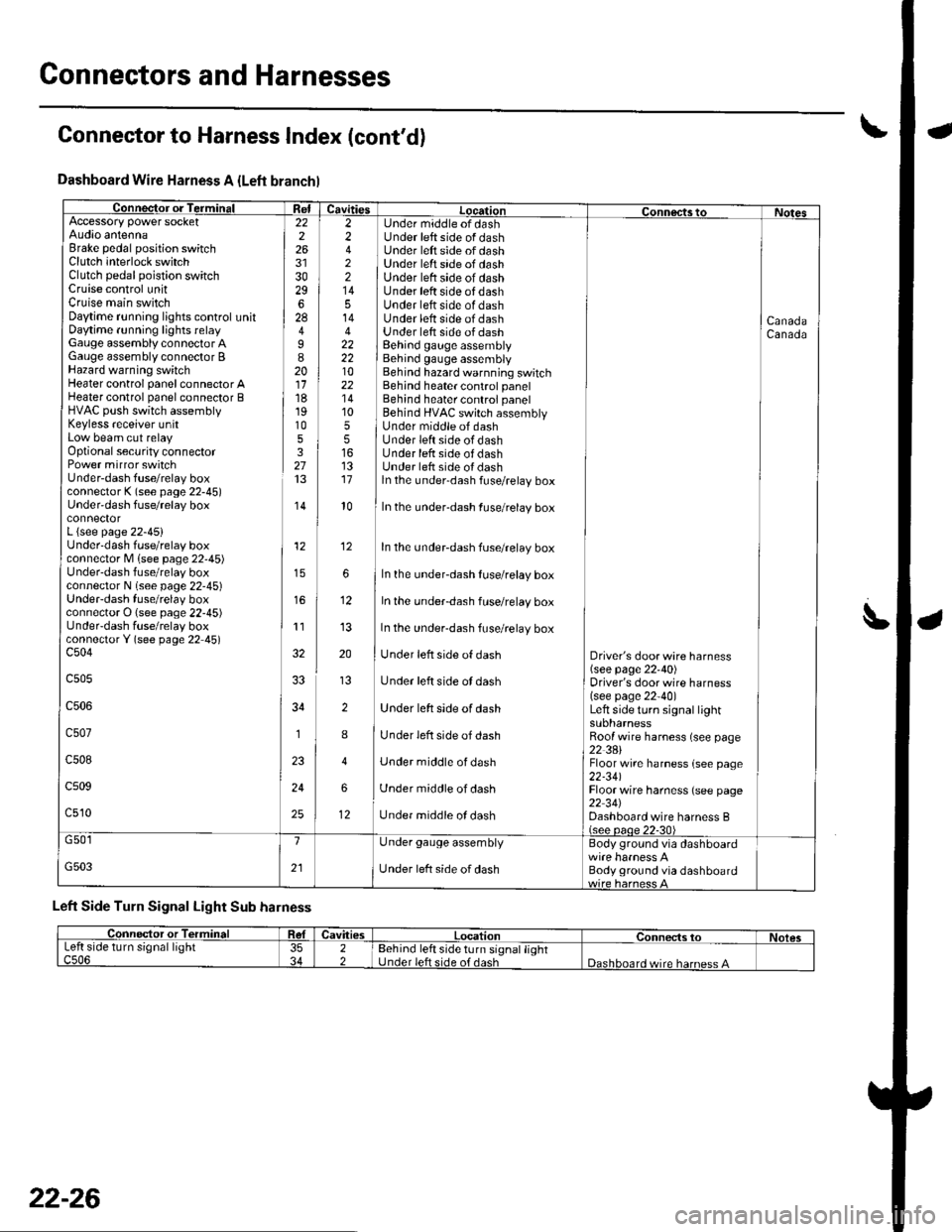
Dashboard Wire Harness A {Left branchl
Connector or TerminalffiAccessory power socketAudio antennaBrake pedal position switchClutch interlock switchClutch pedal poistion switchCruise control unitCruise main switchDaytime r!nning lights control unitDaytime running lights relayGauge assembly connector AGauge assembly connector BHazard warning switchHeater control panel connector AHeater control panel connector BHVAC push switch assemblyKeyless receiver unitLow beam cut relayOptional security connectorPower mirror switchUnder-dash fuse/relay boxconnector K (see page 22-45)Under'dash fuse/relay box
L {see page 22-45}Underdash fuse/relay boxconnector M lsee page 22'45)Under-dash fuse/relay boxconnector N (see page 22-45)UndeFdash fuse/relay boxconnector O (see page 22-45)UndeFdash fuse/relay boxconnectorY (see page 22 45)c504
c505
c506
c507
c508
c509
c510
22226
3029628
I820111819105327
,I4
12
11
34
1
24
25
2 Under middle of dash2 Under left side of dash4 ] Under left side of dash2 ] Under left srde of dash2 | Under left side of dash14 I Under left side of dash5 Under left side of dash14 Under lett side of dash4 Under lett side of dash22 I Behind gauge assembly22 i Behind gauge assembly10 Behind hazard warnning switch22 Behind heater control panel'14 Behind heater control panel10 ] Behind HVAC switch assembly5 I Under middle of dash5 lUnderleftsideofdash16 Under lefr side of dash13 Under left side oI dash17 ln the under-dash fuse/relay box
CanadaCanada
l0In the under-dash fuse/relay box
In the undeFdash fuse/relay box
In the underdash fuse/relay box
In the under-dash fuse/relay box
In the under-dash fuse/relay box
Under left side of dash
Under left side ot dash
Under left side of dash
Under left side of dash
Under middle of dash
Under middle of dash
Under middle ol dash
Driver's door wire harness(see page 22'40)Driver's door wire harness(see page 22-40)Left side turo signal lightsuonarnessRoof wire harness (see page22 3AlFloor wire harness {see page22-341Floor wire harness (see page22 34JDashboard wire harness B(see oaoe 22-30)
12
12
G501
G503
1
21
Under gauge assembly
Under left side of dash
Body ground via dashboard
Body ground via dashboard
Left Side Turn Signal Light Sub harness
Connector to Harness Index (cont'd)
L
Connector or TerminalCavitiesLocationConnects toNolesLeft side turn signal lightc506353422Behind left side turn signal lightUnder left side of dashDashboard wire harness A
22-26
Page 870 of 1139
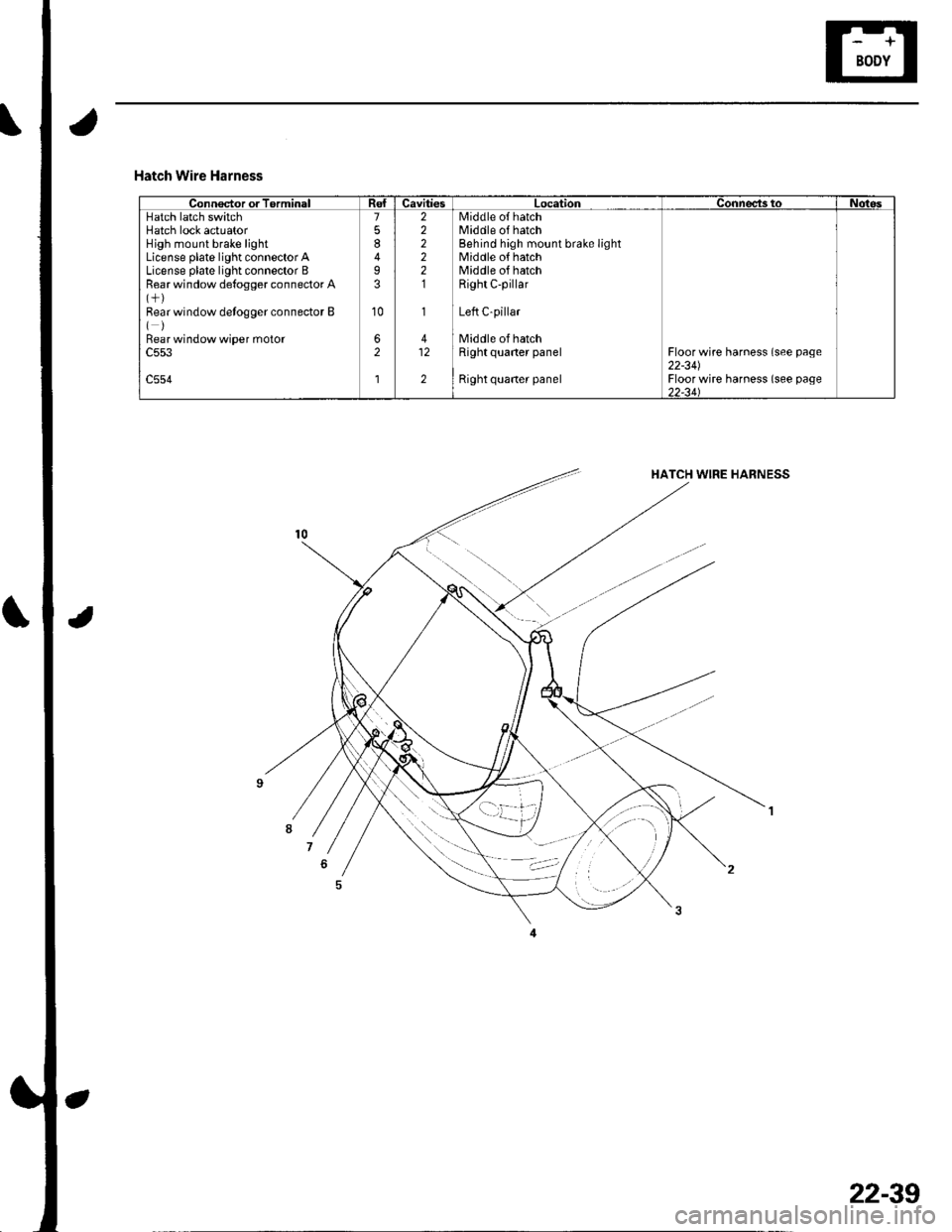
Hatch Wire Harness
Connector or TorminalCavitiesLocationConnects toNotesHatch latch switchHatch lock actuatorHigh mount brake lightLicense plate light connector ALicense plate light connector BRear window de{ogger connector A
Bear window detogger connector B()Bear window wiper moto.c553
c554
7
8
I3
10
62
l
222221
1
412
2
Middle o{ hatchMiddle of hatchBehind high mount brake lightMiddle of hatchMiddle of hatchRight C-pillar
Left C-pillar
Middle of hatchRight quaner panel
Right quaner panel
Floor wire harness (see page22-341Floor wire harness (see page)2-34\
22-39
Page 871 of 1139
Connectors and Harnesses
\,Connector to Harness lndex (cont'd)
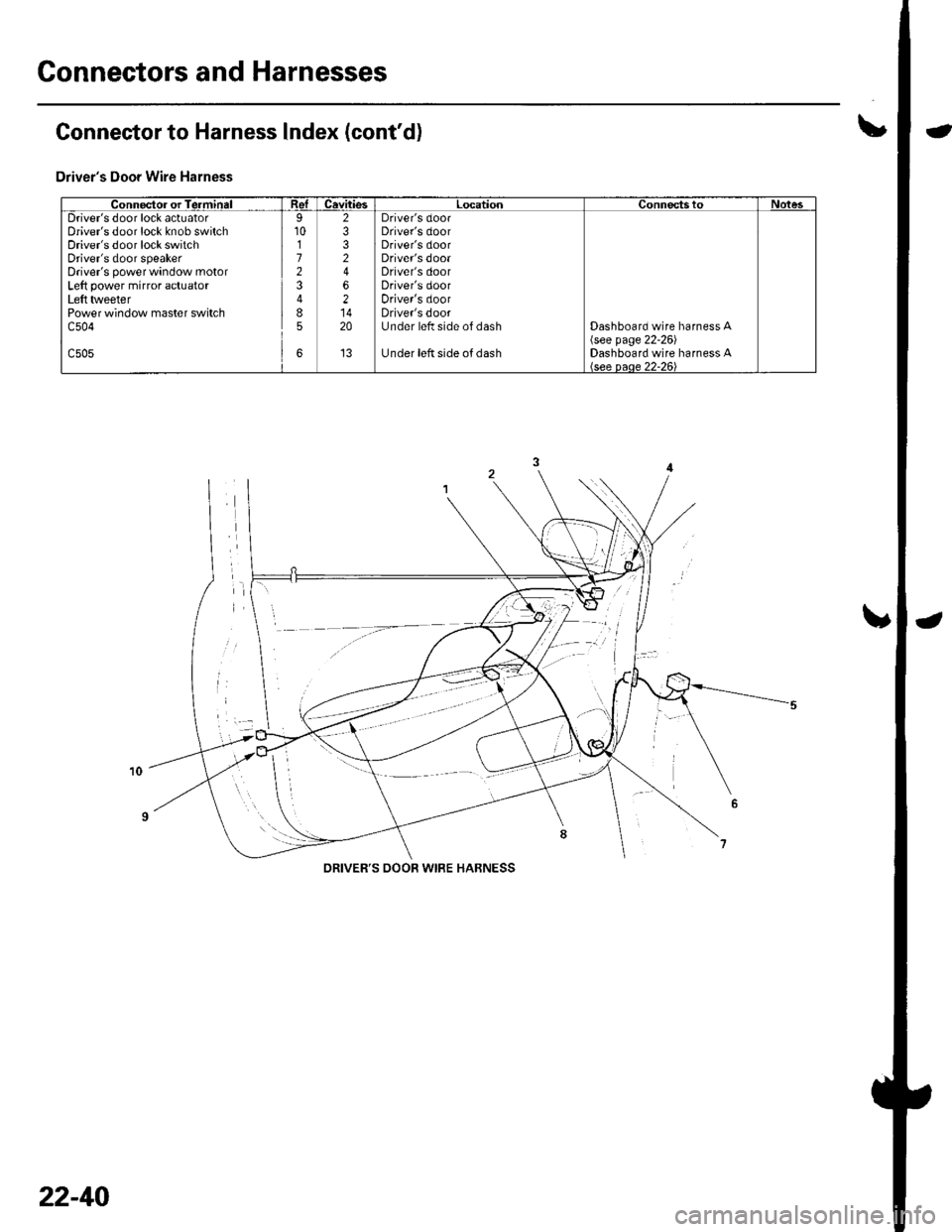
Driver's Door Wire Harness
Connector or TerminalReICavitiesLocationConnectstoNotesDriver's door lock actuatorDriver's door lock knob switchDriver's door lock switchDriver's door speakerDriver's power window motorLeft power mirror actuatorLeft tlveeterPower window master switchc504
c505
9101723
85
6
2332
62
20
't3
Driver's doorDriver's doorDriver's doorDriver's dooaDriver's doorDriver's doorDriver's doorDriver's doorUnder left side of dash
Under left side of dash
Dashboard wire harness A\see page 22-261Dashboard wire harness A
DRIVER'S OOOR WIRE HABNESS
22-40
Page 872 of 1139
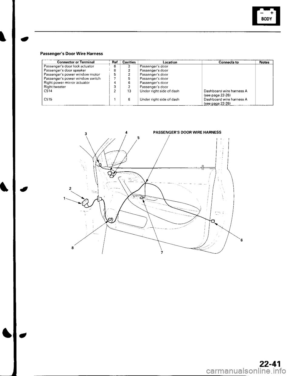
Passenger's Door Wire Harness
Connector or TerminalRelCavitiesLocationConnectstoNotesPassenger's door lock actuatorPassenger's door speakerPassenger's power window motorPassenger's power window switchRight power mirror actuatorRighttweeterc514
6I51432
1
22256213
6
Passenger's doorPassenger's doorPassenger's doorPassenger's doorPassenger's doorPassenger's doorUnder right side of dash
Under right side of dash
Dashboard wire harness A(see page 22'26)Dashboard wire harness Alsee oeoe 22-26\
PASSENGER'S DOOR WIRE HABNESS
22-41
Page 879 of 1139
Ground Distribution
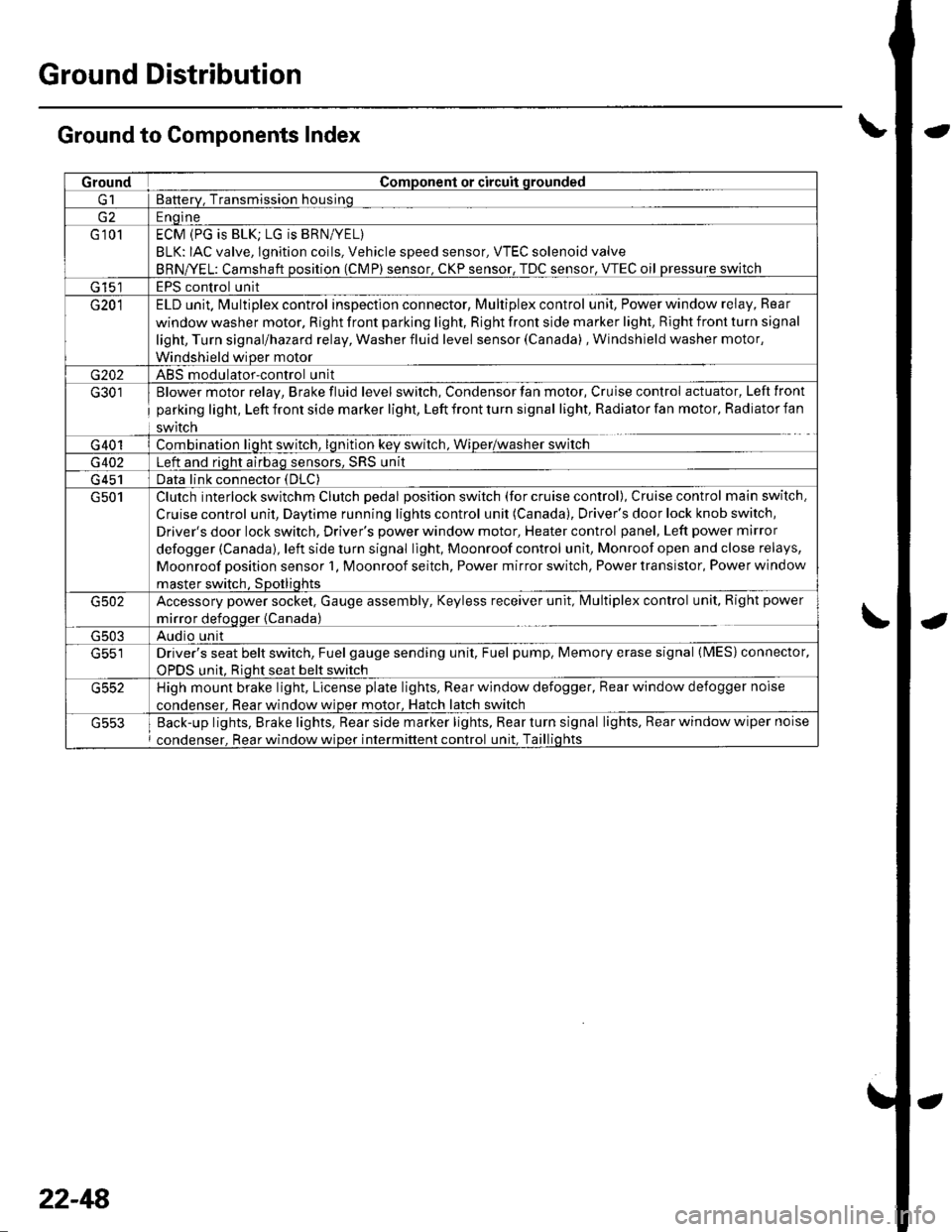
Ground to Components Index
GroundComponent or circuit qrounded
Batterv, Transmission housinq
E ngine
G 101ECM (PG is BLK; LG is BRN/YEL)
BLK: IAC valve, lgnition coils, Vehicle speed sensor, VTEC solenoid valve
BRNA/EL: Camshaft oosition (CMP) sensor. CKP sensor, TDC sensor. VTEC oil pressure switch
G 15'�]EPS control unit
G201ELD unit. Multiplex control inspection connector, Multiplex control unit, Power window relay, Rear
window washer motor, Right front parking light, Right front side marker light, Right front turn signal
light, Turn signal/hazard relay, Washer fluid level sensor (Canada) , Windshield washer motor,
Windshield wiDer motor
G202ABS modulator-control unit
G301
G401
Blower motor relay, Brake fluid level switch, Condensor fan motor, Cruise control actuator, Left front
parking light, Left front side marker light, Left front turn signal light, Radiator fan motor, Radiator fan
swrtcn
Combination liqht switch, lqnitlon kev srvitch, Wiper/wasfrer sr,virch
G402Left and riqht airbaq sensors, SRS unit
G 451Data link connector (DLC)
G501Clutch interlock switchm Clutch pedal position switch (for cruise control), Cruise control main switch,
Cruise control unit, Daytime running lights control unit (Canada), Driver's door lock knob switch,
Driver's door lock switch, Driver's power window motor, Heater control panel, Left power mirror
defogger (Canada), left side turn signal light, Moonroof control unit, Monroof open and close relays,
Moonroof position sensor '1, Moonroof seitch, Power mirror switch, Power transistor, Power window
master switch. SDotliqhts
G502Accessory power socket, Gauge assembly, Keyless receiver unit, lvlultiplex control unit, Right power
mirror defogger {Canada)
G503Audio unit
G551Driver's seat belt switch, Fuel gauge sending unit, Fuel pump, Memory erase signal (IMES) connector,
OPDS unit. Rioht seat belt switch
G552High mount brake light, License plate lights, Rear window defogger, Rear window defogger noise
condenser. Rear window wioer motor, Hatch latch switch
Back-up lights, Brake lights, Rear side marker lights, Rear turn signal lights, Rear window wiper noise
condenser, Rear window wiper intermittent control unit, Taillights
22-48
Page 880 of 1139
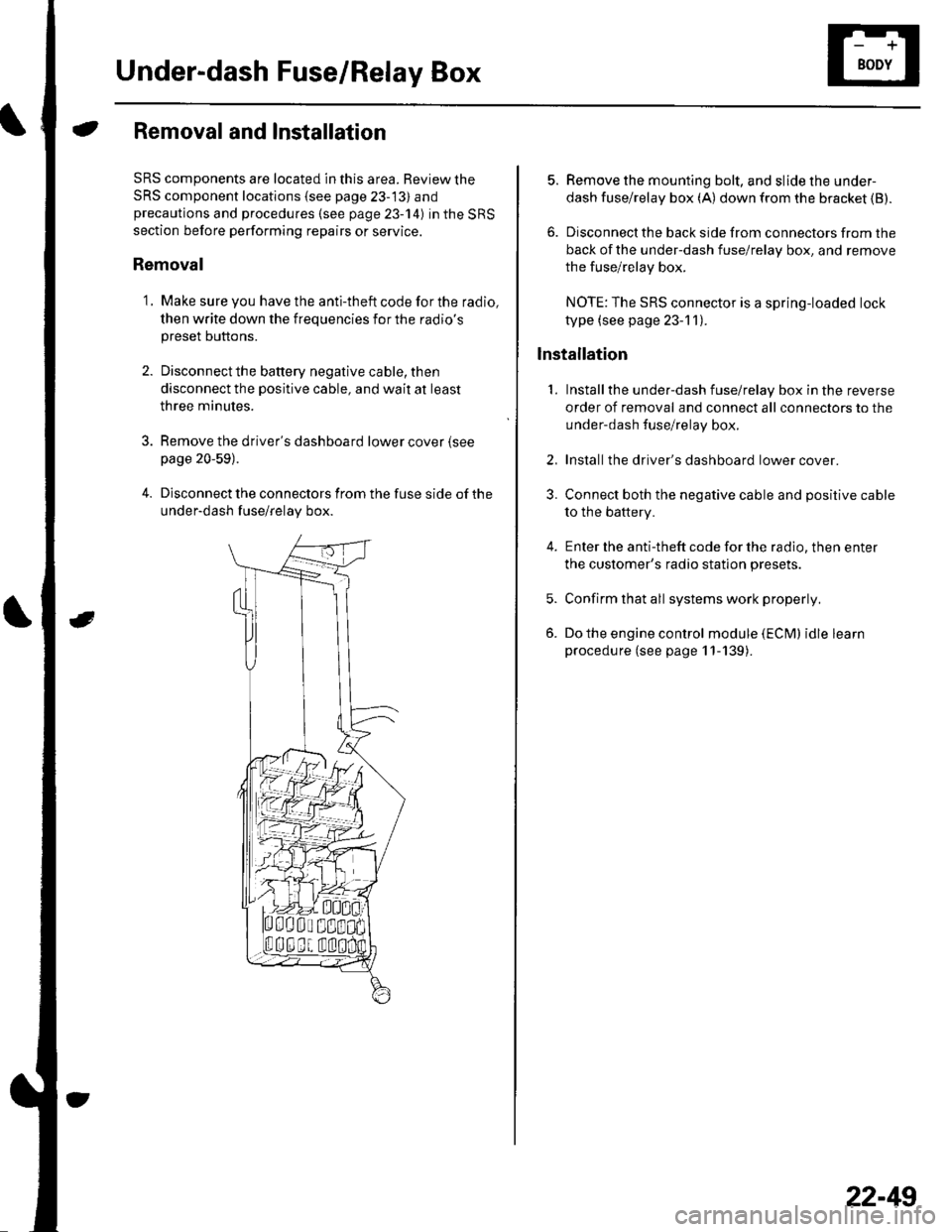
Under-dash Fuse/Relay Box
Removal and Installation
SRS components are located in this area. Review the
SRS component locations {see page 23-13) andprecautions and procedures (see page 23-14) in the SRS
section before performing repairs or service.
Removal
1. Make sure you have the anti-theft code for the radio,
then write down the frequencies for the radio's
preset buttons.
2. Disconnectthe battery negative cable, then
disconnect the positive cable, and wait at least
three minutes.
3. Remove the driver's dashboard lower cover (see
page 20-59).
4. Disconnect the connectors from the fuse side of the
under-dash fuse/relay box.
5. Remove the mounting bolt, and slide the under-
dash fuse/relay box (A) down from the bracket {B).
6. Disconnect the back side from connectors from the
back of the under-dash fuse/relay box, and remove
the fuse/relay box.
NOTE:The SRS connector is a spring-loaded lock
type (see page 23-1 1).
lnstallation
1. Installthe under-dash fuse/relay box in the reverse
order of removal and connect all connectors to the
under-dash fuse/relay box.
2. Installthe driver's dashboard lower cover.
3. Connect both the negative cable and positive cable
to the battery.
4. Enter the anti-theft code for the radio, then enter
the customer's radio station presets.
5. Confirm that all systems work properly,
6. Do the engine control module (ECM) idle learn
procedure (see page 11-139).
22-49
Page 884 of 1139
lgnition Switch
Test
SRS components are located in this area. Review the
SRS component locations (see page 23-13) andprecautions and procedures {see page 23-'l4) in the SRS
section before performing repairs or service.
1, Remove the driver's dashboard lower cover {seepage 20-59).
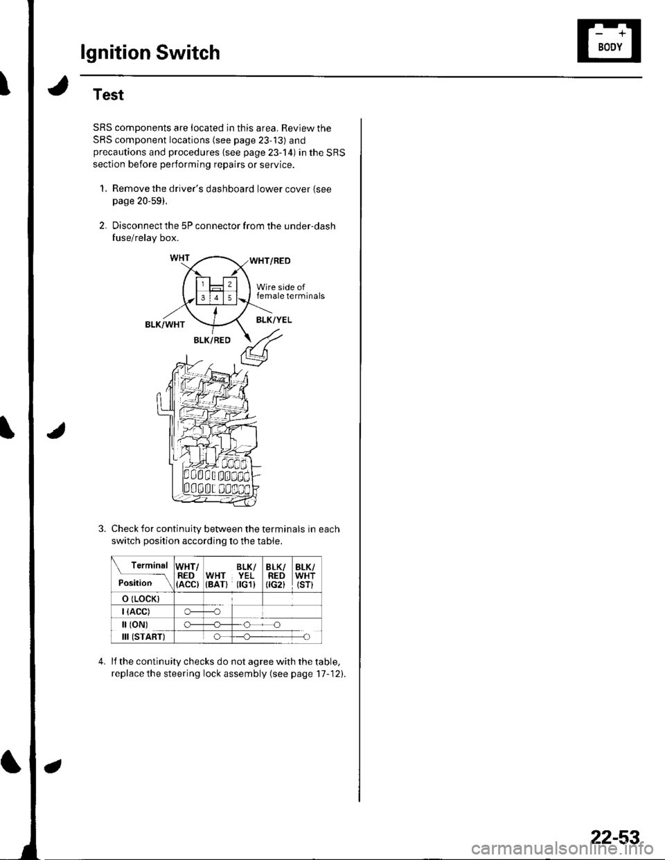
2. Disconnect the 5P connector from the under-dash
fuse/relay box.
WHT/RED
Wire side offemale terminals
BLK/WHTBLK/YEL
BLK/RED
Check for continuity between the terminals in each
switch position according to the table.
Terminal
p.J,i""-\
WHT/RED(ACC)
BLK/WHT YEL(BAT) flGl)
BLK/REDtrc2t
BLK/WHT(sr)
o (LocK)
| (ACC)o---o
[ (oN)
III (START)
c)-_H
o_H
lf the continuity checks do not agree with the table,
replace the steering lock assembly (see page'17-121.
22-53