lock HONDA CIVIC 2002 7.G Workshop Manual
[x] Cancel search | Manufacturer: HONDA, Model Year: 2002, Model line: CIVIC, Model: HONDA CIVIC 2002 7.GPages: 1139, PDF Size: 28.19 MB
Page 989 of 1139
I
Keyless/Power Door Lock System
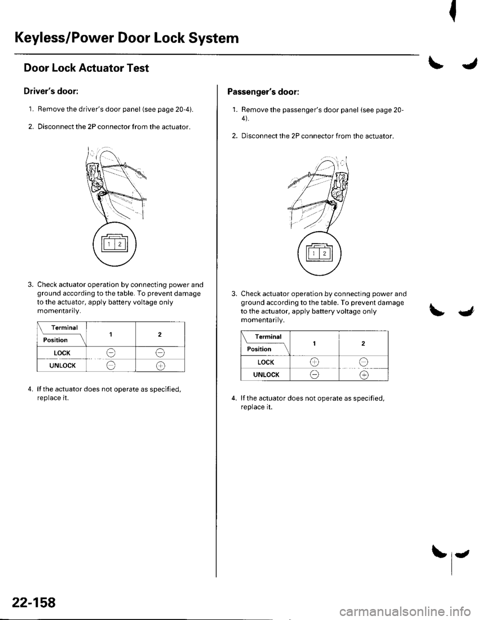
Door Lock Actuator Test
Driver's door:
1. Remove the driver's door panel (seepage20-4).
2. Disconnect the 2P connector from the actuator.
Check actuator operation by connecting power and
ground according to the table. To prevent damage
to the actuator, apply battery voltage only
momenlanry.
Terminal
ilil;lll
'l2
LOCKee
UNLOCKee
lf the actuator does not operate as specified,
reprace rr.
4.
22-158
Passenger's door:
1. Remove the passenger's door panel (seepage20-
4).
2. Disconnect the 2P connector from the actuator,
Check actuator operation by connecting power and
ground according to the table. To prevent damage
to the actuator, apply battery voltage only
momenlanty.
Terminal
P."I,l.;--\2
LOCKee
UNLOCKeo
lf the actuator does not operate as specified,
reprace [,
Page 990 of 1139
J
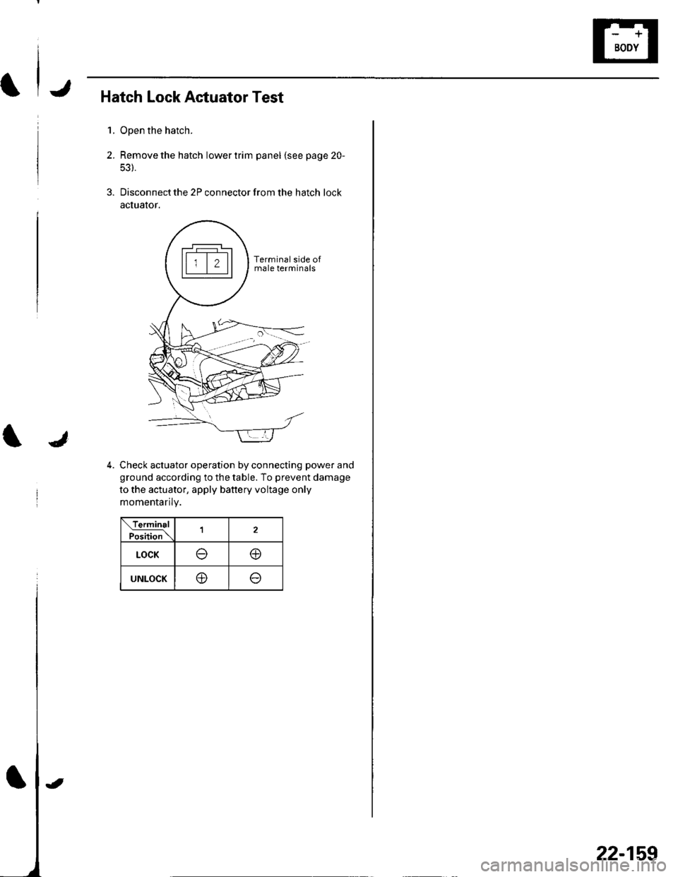
Hatch Lock Actuator Test
1. Open the hatch.
2. Remove the hatch lower trim panel lsee page 20-
53).
3. Disconnect the 2P connector from the hatch lock
actualor.
4. Check actuator operation by connecting power and
ground according to the table. To prevent damage
to the actuator, apply battery voltage only
momentaflty.
\TerminalPo.irion\1
LOCK@
UNLOCKo
Terminal side ofmale terminals
22-159
Page 991 of 1139
Keyless/Power Door Lock System
1.
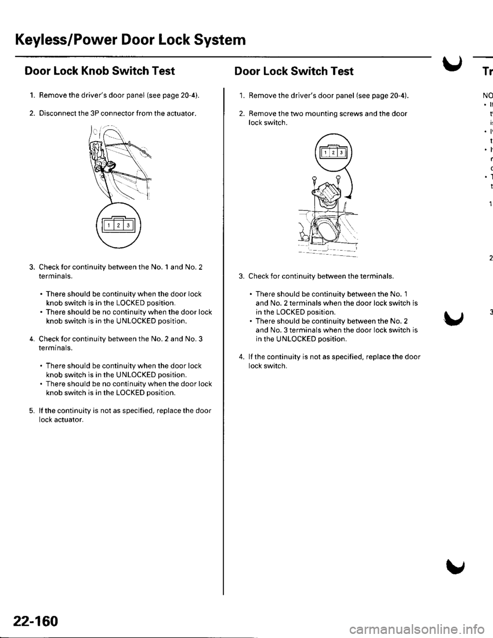
Door Lock Knob Switch Test
Remove the driver's door panel (see page 20-4).
Disconnect the 3P connector from the actuator.
Check for continuity between the No. 1 and No. 2
term ana ls.
. There should be continuity when the door lock
knob switch is in the LOCKED position.
. There should be no continuity when the door lock
knob switch is in the UNLOCKED position.
Check for continuity between the No. 2 and No. 3
termtnals.
. There should be continuity when the door lock
knob switch is in the UNLOCKED position.
. There should be no continuity when the door lock
knob switch is in the LOCKED position.
lf the continuity is not as specified, replace the door
locl( actuator.
5.
22-160
'1.
Door Lock Switch Test
Remove the driver's door panel (see page 20-4).
Remove the two mounting screws and the door
lock switch.
Check for continuity between the terminals.
. There should be continuity between the No. 1
and No. 2 terminals when the door lock switch is
in the LOCKED position.. There should be continuity between the No. 2
and No. 3 terminals when the door lock switch is
in the UNLOCKED position.
lf the continuity is not as specified. replace the door
lock switch.
Tr
NO
I
.ti
I.l
I
(
.1
I
1
Page 992 of 1139
Transmitter Test
NOTE:. lf the doors unlockorlockwiththetransmitter, but
the LED on the transmitter does not come on, the LED
is faulty. Replace the transmitter,. lf anydoor isopen, you cannotlockthedoorwiththe
transmrtter.. lf you unlocked the doors with the transmitter, but do
not open any of the doors within 30 seconds, the
doors relock automatically.. The doors do not lock or unlock with the transmitter if
the ignition key is inserted in the ignition switch.
1. Press the lock or unlock button five or six times to
reset the transmitter.
. lf the locks work, the transmitter is OK.. lf the locks don't work, go to step 2.
2. Open the transmitter and check for water damage.
. lf you find any water damage, replace the
transmrtter.. lf there is no waterdamage, go to step 3.
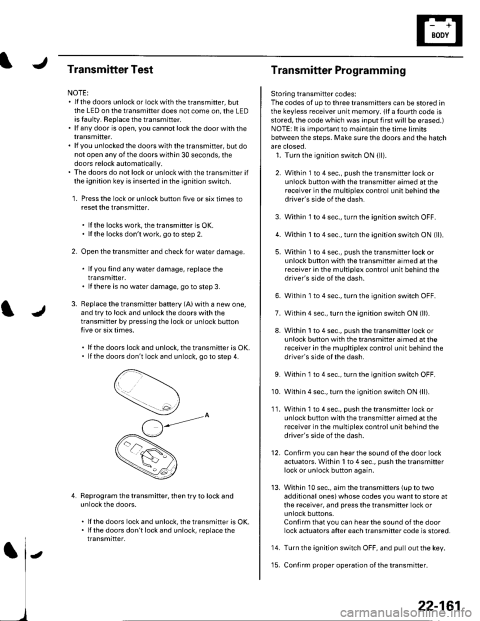
3. Replace the transmitter battery (A) with a new one,
and try to lock and unlock the doors with the
transmitter by pressing the lock or unlock button
five or six times.
. lf the doors lock and unlock, the transmifter is OK.. lf the doors don't lock and unlock, go to step 4.
Reprogram the transmitter, then try to lock and
unlock the doors.
. lf thedoors lockand unlock.thetransmitter is OK.. lf the doors don'tlockand unlock, replacethe
transmitter.
4.
Transmitter Programming
Storing transmitter codes:
The codes of up to three transmitters can be stored in
the keyless receiver unit memory. (lf a fourth code is
stored. the code which was input first will be erased.)
NOTE: lt is important to maintain the time limits
between the steps. Make sure the doors and the hatch
are closed.
1. Turn the ignition switch ON (lli.
2. Within 1 to 4 sec., push the transmitter lock or
unlock button with the transmitter aimed at the
receiver in the multiplex control unit behind the
driver's side of the dash.
3. Within 1 to 4 sec., turn the ignition switch OFF.
4. Within 1 to 4 sec., turn the ignition switch ON (ll).
5. Within 'l to 4 sec., push the transmitter lock or
unlock button with the transmitter aimed at the
receiver in the multiplex control unit behind the
driver's side of the dash.
6. Within 1 to 4 sec., turn the ignition switch OFF.
7. Within 4 sec., turn the ignition switch ON (ll).
8. Within 1 to 4 sec., push the transmitter lock or
unlock button with the transmifter aimed at the
receiver in the mupltiplex control unit behind the
driver's side of the dash.
9. Within 1 to 4 sec., turn the ignition switch OFF,
'10. Within 4 sec., turn the ignition switch ON (ll).
11. Within 1 to 4 sec., push the transmitter lock or
unlock button with the transmitter aimed at the
receiver in the multiplex control unit behind the
driver's side of the dash.
12. Confirm you can hearthe sound ofthe door lock
actuators. Within 1 to 4 sec., push the transmitter
lock or unlock button again,
13, Within 10 sec., aim the transmitters (up to two
additional ones) whose codes you want to store at
the receiver, and press the transmitter lock or
unlock buttons.
Confirm that you can hear the sound of the door
lock actuators after each transmitter code is stored.
14. Turn the ignition switch OFF, and pull out the key.
'15. Confirm proper operation ofthe transmitter.
22-161
Page 1002 of 1139
ISystem Descriptions
The Multiplex Control System has four internal
functions:. Multiplexing (send multiple signals over sharedwtres). Wake up/sleep (runs at full power only on demand toreduce battery draw). Fail-safe (fixes or ignores faulty signals). Self-diagnosis (Mode 1 for the system, Mode 2 for
input lines)
The system controls the function of these circuits:. Entry lightcontrol (ignition key lightandceiting light). Wiper/washer intermittent wipe and park functions. Keyless/power door lock. Meter assembly, temperature gauge, and indicator
lights. HVAC (compressor and fan control). Key-in reminder. Headlight reminder. Seatbelt reminder
JI
/ar
22-171
Multiplex Communication
To reduce the number of wire harnesses, digital signals
are sent via shared multiplex communication linesrather than sending normal electrical signals throughindividual wires.. The input signals from each switch are converted todigital signals at the central processing unit (CpU).. The digital signalsaresentfromthetransmitting unitto the receiving unit as serial signals.. The transmitted signal is converted to a switch signalat the receiving unit, and it operates the related
component or monitors a swltch.. There are exclusive communicalion lines between
the ECM, the gauge assembly, and the under,dash
fuse/relay box.
Wake-up and Sleep
The multiplex control system has "wake-up" and"sleep" functions to decrease parasitic draw on the
battery when the ignition switch is OFF.. ln the sleep mode, the multiplex control unit stops
functioning (communication and CPU control) when it
is not necessary for the system to operate.. As soon as any operation is requested (for example, adoor is unlocked), the related control unit in the sleep
mode immediately wakes up and begins to function.. When the ignition switch is turned OFF, and the
driver's or front passenger's door is opened, then
closed, there is about a 10 second delay before the
control unit goes from the wake-up mode to the sleepmode.. lf any door is open, the sleep mode will not function.. lf a key is in the ignition switch, the sleep mode will
not function.. When in sleep mode, the draw is reduced from
70 80 mA to less than 10 mA.
Fail-safe
To prevent improper operation, the multiplex controlsystem has a fail-safe function. In the fail-safe mode,
the output signal js fixed when any part of the systemmalfunctions (for example a faulty control unit orcommunication line).
Each control unit has a hardware fail-safe function thatfixes the output signal when there is any CPUmalfunction, and a software fail-safe function thatignores the signal from the malfunctioning control unitand allows the system to operate normally.
Page 1013 of 1139
9.
10.
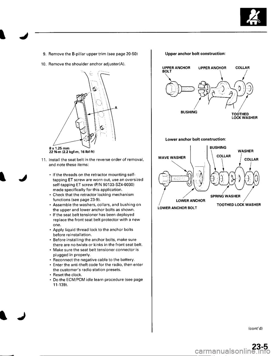
Remove the B-pillar upper trim {see page 20-50)
Remove the shoulder anchor adjuster{A).
22 N.m (2.2 kgf.m, 16lbf.ftl
Installthe seat belt in the reverse order of removal,
and note these items:
. lf thethreads on the retractor mounting self-
tapping ET screw are worn out, use an oversized
self-tapping ET screw (P/N 90133-SZ4-0030)
made specifically for this application.. Check that the retractor locking mechanism
functions (see page 23-9).. Assemble the washers, collars, and bushing on
the upper and lower anchor bolts as shown.. lf the seat belt tensioner has been deployed
replace the front seat belt protector with a new
one.. Apply liquid thread lock to the anchor bolts
before reinstallation.. Before installing the anchor bolts, make sure
there are no twists or kinks in the front seat belt.. Make sure the seat belt tensioner connector is
plugged in properly.
. Reconnect the negative cable to the battery.. Enter the anti-theft code for the radio, then enter
the customer's radio station presets.
. Reset the clock.. Do the ECM/PCM idle learn procedure {see page
11,139).
11.
8 x 1.25 mm
UPPER ANCHORBOLT
BUSHING
Upper anchor bolt construction:
UPPER ANCHOR
Lower anchor bolt construction:
COLLAR
TOOTHEDLOCK WASHER
LOWER ANCHOR BOLTTOOTHED LOCK WASHER
{cont'd)
WASHER
23-5
Page 1014 of 1139
Seat Belts
Front Seat Belt Replacement (cont'd)
Seat Belt Buckle
1. Make sure you have the anti-theft code for the radio,
then write down the frequencies for the preset
buttons.
2. Disconnect the negative cable from the battery ,and wait at least 3 minutes before beginning work.
3. Remove the front seat (see page 20-7'1).
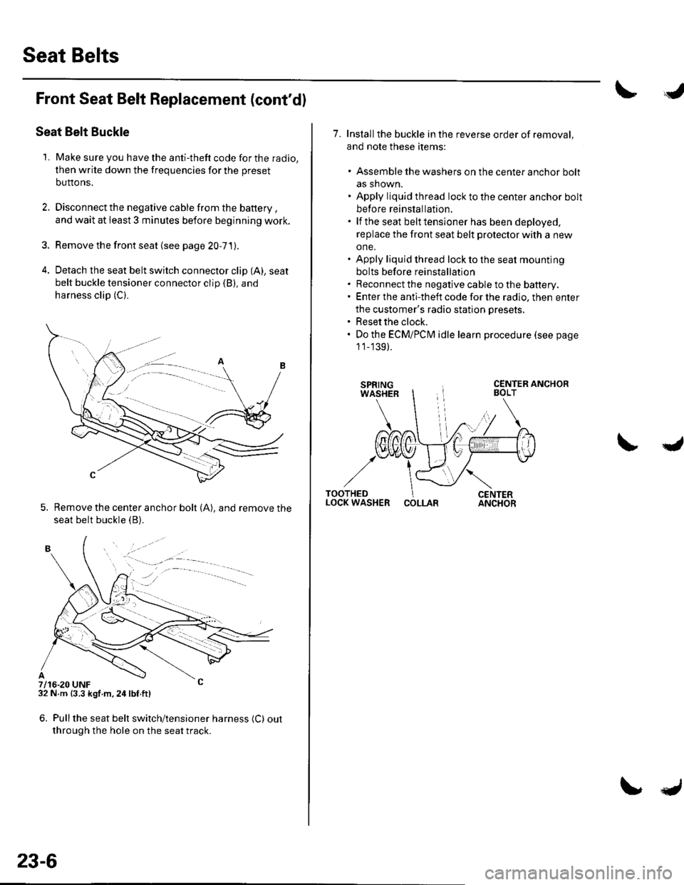
4. Detach the seat belt switch connector clip (A), seat
belt buckle tensioner connector clip (B), and
harness clip (C).
5. Remove the center anchor bolt (A), and remove the
seat belt buckle {B).
7/16-20 UNF32 N m {3.3 kgf m,24lbf.ft)
6. Pullthe seat belt switch/tensioner harness (C) out
through the hole on the seat track.
. -.. :.a--
23-6
7. Installthe buckle in the reverse order of removal,
and note these items:
. Assemble the washers on the center anchor bolt
as shown.. Apply liquid thread lock to the center anchor bolt
before reinstallation.. lf the seat belt tensioner has been deployed,
replace the front seat belt protector with a new
one.. Apply liquid thread lock to the seat mounting
bolts before reinstallation. Reconnect the negative cable to the battery.. Enter the anti-theft code for the radio, then enter
the customer's radio station presets.. Reset the clock.. Do the ECMiPCM idle learn procedure (see page
1 1_139).
COLLAR
Page 1015 of 1139
I
I
Rear Seat Belt Replacement
NOTE: Check the rear seat belts for damage, and
replace them if necessary. Be careful not to damage
them during removal and installation.
Rear Seat Belt
1. Remove the rear seat cushion (see page 20 80).
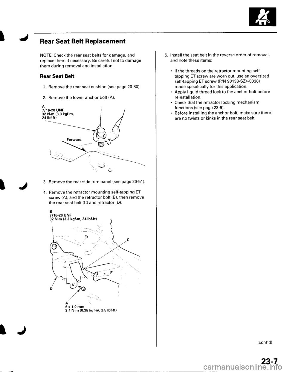
2. Remove the lower anchor bolt {A}.
l.\J,
Remove the rear side trim panel (see page 20-51).
Remove the retractor mounting self-tapping ET
screw (A), and the retractor bolt (B), then remove
the rear seat belt (C) and retractor {D).
B7/16-20 UNF
3,
4.
A6x1.0mm3.4 N.m {0.35 kgl m,2.5 lbf.ftl
A7/16-20 UNF32 N.m (3.3 kgf.m,24 tbf.ftl
N m {3.3 kgf.m,2ir lbf.ft)
5. Installthe seat belt in the reverse order of removal,
and note these items:
. lf the threads on the retractor mounting self-
tapping ET screw are worn out, use an oversized
self-tapping ET screw (P/N 90133-524-0030)
made specifically for this application.. Apply liquid thread lock to the anchor bolt before
reinstallation.' Check that the retractor locking mechanism
functions {see page 23-9).. Before installing the anchor bolt, make sure there
are no twists or kinks in the rear seat belt.
(cont'd)
23-7
Page 1017 of 1139
I
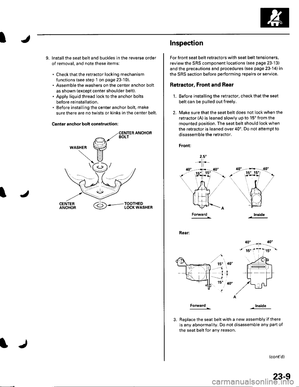
9. lnstallthe seat belt and buckles in the reverse order
of removal, and note these items:
. Check that the retractor locking mechanism
functions (see step 1 on page 23-10).. Assemble the washers on the center anchor bolt
as shown (except center shoulder belt).. Apply liquid thread lock to the anchor bolts
before reinstallation.. Before installing the center anchor bolt, make
sure there are no twlsts or kinks in the center belt,
Canler anchor bolt construction:
WASHER
Inspec'tion
For front seat belt retractors with seat belt tensioners.
reviewthe SRS component locations (see page 23-13)
and the precautions and procedures (see psge 23-14) in
the SRS section before performing repairs or service.
Retractor, Front and Rear
1. Before installing the retractor, check that the seat
belt can be pulled out freely.
2. l\4ake sure that the seat belt does not lock when the
retractor (A) is leaned slowly up to 15'from the
mounted position. The seat belt should lock when
the retractor is leaned over 40'. Do not attemDt to
disassemble the retractor.
Front:
Rear:
Forward
Forward
lnside
Inside
Replace the seat belt with a new assembly if there
is any abnormality. Do not disassemble any pan of
the seat belt for any reason,
(cont'd)
23-9
Page 1018 of 1139
Seat Belts
Inspection (cont'd)
RetraEtor, Rear Center
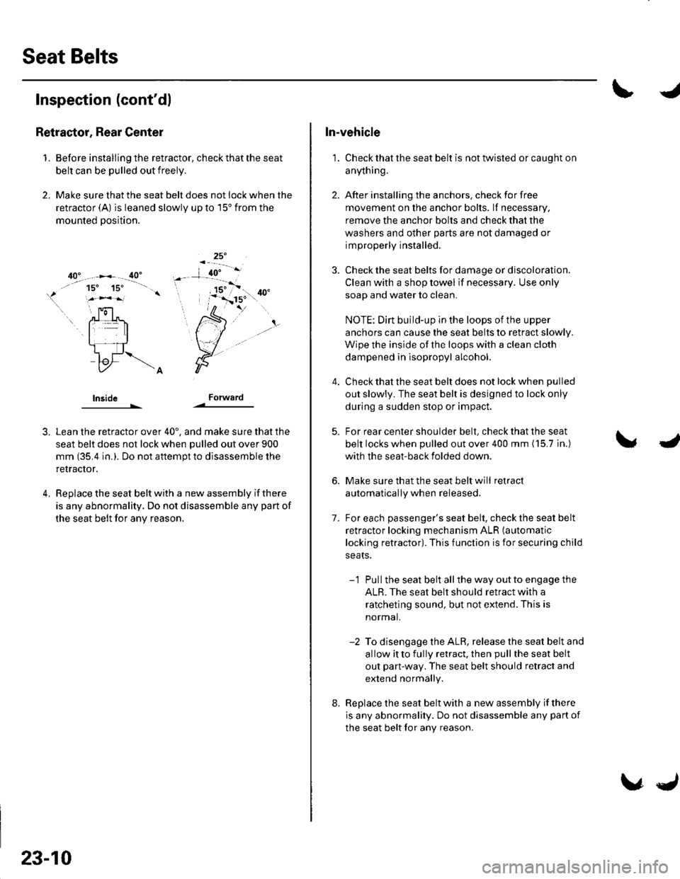
1. Before installing the retractor, check that the seat
belt can be pulled out freely.
2, Make sure that the seat belt does not lock when the
retractor (A) is leaned slowly up to 15' from the
mounted position.
lnsideForward
3,
4.
Lean the retractor over 40', and make sure that the
seat belt does not lock when pulled out over 900
mm (35.4 in.). Do not aftempt to disassemble the
retractor.
Replace the seat belt with a new assembly if there
is any abnormality. Do not disassemble any part of
the seat belt for any reason.
23-10
\,J
In-vehicle
1. Check that the seat belt is not twisted or caught on
anything.
2. After installing the anchors. check for free
movement on the anchor bolts. lf necessary,
remove the anchor bolts and check that the
washers and other parts are not damaged or
improperly installed.
3. Check the seat belts for damage or discoloration.
Clean with a shop towel if necessary. Use only
soap and water to clean.
NOTE: Dirt build-up in the loops of the upper
anchors can cause the seat belts to retract slowly.
Wipe the inside of the loops with a clean cloth
dampened in lsopropyl alcohol.
Check that the seat belt does not lock when pulled
out slowly. The seat belt is designed to lock only
during a sudden stop or impact.
For rear center shoulder belt, check that the seat
belt locks when pulled out over 400 mm (15.7 in.)
with the seat-back folded down.
Make sure that the seat belt will retract
automatically when released.
For each passenger's seat belt, check the seat belt
retractor locking mechanism ALR (automatic
locking retractor). This function is for securing child
seats.
-1 Pullthe seat belt allthe way outto engage the
ALR. The seat belt should retract with a
ratcheting sound, but not extend. This is
normal.
-2 To disengage the ALR, release the seat belt and
allow itto fully retract, then pullthe seat belt
out part-way. The seat belt should retract and
extend normally.
Replace the seat belt with a new assembly if there
is any abnormality. Do not disassemble any part of
the seat belt for any reason.
7.
8.