dashboard HONDA CIVIC 2002 7.G Service Manual
[x] Cancel search | Manufacturer: HONDA, Model Year: 2002, Model line: CIVIC, Model: HONDA CIVIC 2002 7.GPages: 1139, PDF Size: 28.19 MB
Page 863 of 1139
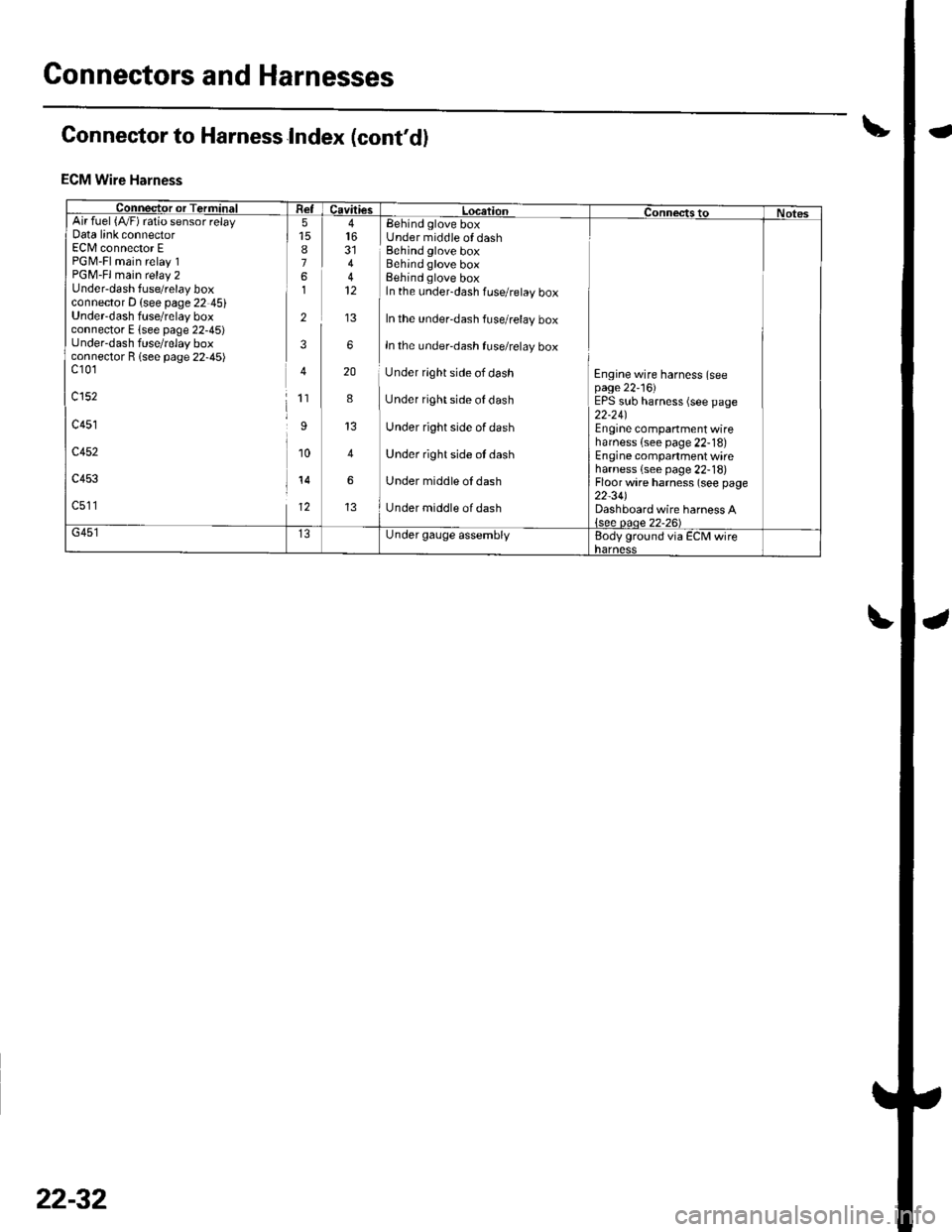
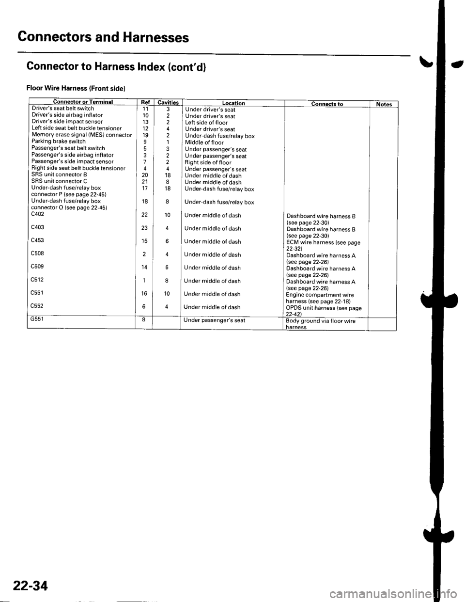
Connectors and Harnesses
Connector to Harness Index (cont'd)
ECM Wire Harness
Connector or TerminiFI Re-lcavitiesL LocationConnectstoNotesArr ruer t/vrl ralo sensor retayData link connectorEC[/l connector EPGM-Fl main relay 1PGM-Fl main relay 2Under-dash fuse/relay boxconnector D (see page 22 45)Underdash fuse/relay boxconnector E lsee page 22-45)under-dash fuse/relay boxconnector R lsee page 22-45)c10'1
c152
c451
c452
c453
c511
8761
2
3
4
1'�I
I
10
14
12
44
6
20
8
4
6
Eehind glove boxUnder middle of dashBehind glove boxBehind glove boxBehind glove boxIn the under-dash fuse/relay box
In the under-dash fuse/relay box
In the under-dash fuse/relay box
Under rlght side of dash
Under right side of dash
Under right side of dash
Under right side ot dash
Under middle oI dash
Under middle of dash
Engine wire harness (seepage 22'16)EPS sub harness (see page22-24)Engine companment wireharness {see page 22-18)Engine compartment wireharness {see page 22-18)Floor wire harness (see page22-34)Dashboard wire harness A{see oaoe 22-26)G451Under gauge assemblyBody ground via ECM wireharness
22-32
Page 865 of 1139
Connectors and Harnesses
Connector to Harness lndex (cont'd)
Floor Wire Harness (Front sidel
Connec-tor or TerminalI Refuavftres Location connects to Nol6sDriver's seat belt switchDriver's side airbag inflatorDriver's side impact sensorLeft side seat belt buckle tensionerMemory erase signal (MES) connectorParking brake switchPassenger's seat belt switchPassenger's side airbag inflatorPassenger's side impact sensorRight side seat belt buckle tensionerSRS unit connector BSRS unit connector CUnder-dash fuse/relay boxconnector P {see page 22-45)Under-dash fuse/relay boxconnector O (see page 22,45)c402
c403
c453
c508
c509
c512
11l013121995374202111
'r8
22
23
2
14
1
6
3 I Under driver's seat2 i Under driver's seat2 I Left side offloor4 Under driver's seat2 Under dash fuse/relay box1 1 Middle offloor3 Under passenger's seat2 Under passenger's seat2 Right side offloor4 Under passenger's seat18 I Under middle of dash8 Under middle of dash18 Underdash fuse/relay box
8
]
Under dash fuse/relay box
10
I
Under middle of dash
4 Under middle of dash
6 Under middle of dash
4 Under middle of dash
6 Under middle ofdash
8
I
Under middle of dash
10 Under middle of dash
4 ] Unaer middle of aasn
Dashboard wire harness B{see page 22 30)Dashboard wire harness B(see page 22-30)ECM wire harness (see page22-321Dashboard wire harness A(see page 22-26)Dashboard wire harness A\see page 22-26)Dashboard wire harness A{see page 22-26)Engine compartment wireharness (see page 22 18)OPDS unit harness (see page22-421G551IL,nder passenger's seatBody ground via floor wire
22-34
Page 869 of 1139
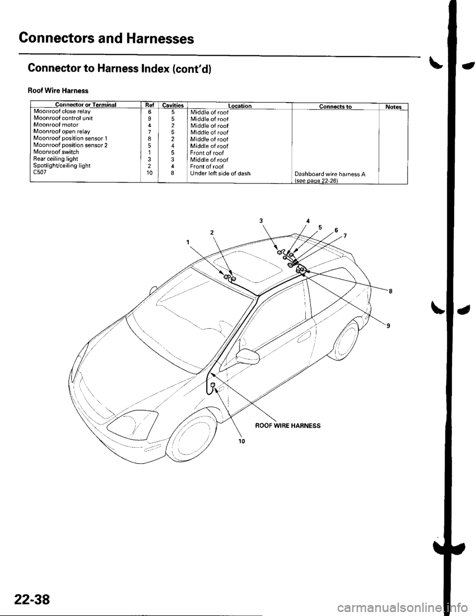
Connectors and Harnesses
Connector to Harness Index (cont'd)
Roof Wire Harnsss
Connector or TerminalCavitiestocationConnectstoNotesMoonroofclose relayMoonrool control unitMoonroof motorMoonroot open relayMoonroof position sensor 1N4oonroof position sensor 2MoonroofswitchRear ceiling lightSpotlighVceiling lightc507
6I
7851
210
5525245348
Middle of roofMiddle of roofMiddle of roofMiddle of roofMiddle oI roofMiddle of roofFront of roofN4iddle of roofFront of roofUnder left side of dashDashboard wire harness A(see oaoe 22-261
22-38
Page 871 of 1139
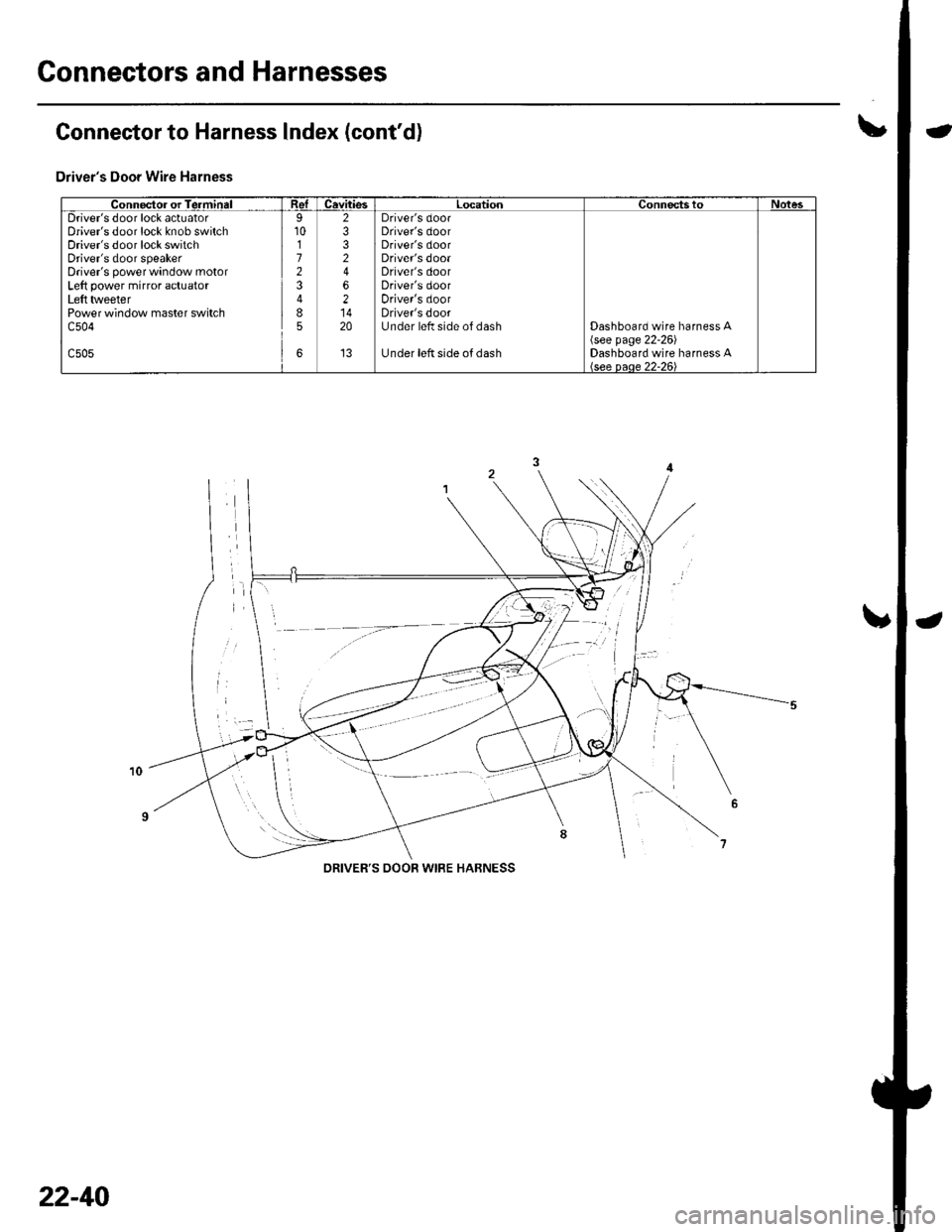
Connectors and Harnesses
\,Connector to Harness lndex (cont'd)
Driver's Door Wire Harness
Connector or TerminalReICavitiesLocationConnectstoNotesDriver's door lock actuatorDriver's door lock knob switchDriver's door lock switchDriver's door speakerDriver's power window motorLeft power mirror actuatorLeft tlveeterPower window master switchc504
c505
9101723
85
6
2332
62
20
't3
Driver's doorDriver's doorDriver's doorDriver's dooaDriver's doorDriver's doorDriver's doorDriver's doorUnder left side of dash
Under left side of dash
Dashboard wire harness A\see page 22-261Dashboard wire harness A
DRIVER'S OOOR WIRE HABNESS
22-40
Page 872 of 1139
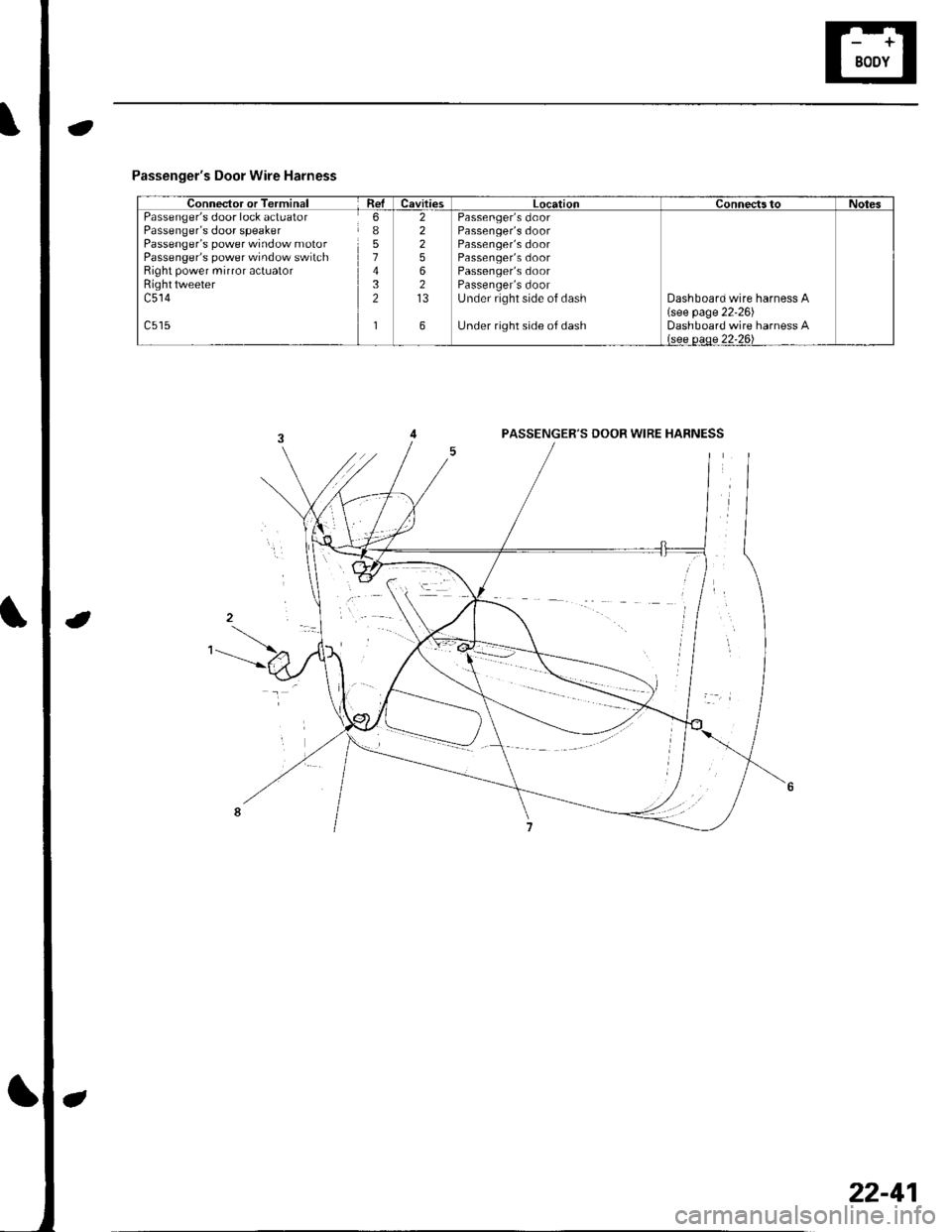
Passenger's Door Wire Harness
Connector or TerminalRelCavitiesLocationConnectstoNotesPassenger's door lock actuatorPassenger's door speakerPassenger's power window motorPassenger's power window switchRight power mirror actuatorRighttweeterc514
6I51432
1
22256213
6
Passenger's doorPassenger's doorPassenger's doorPassenger's doorPassenger's doorPassenger's doorUnder right side of dash
Under right side of dash
Dashboard wire harness A(see page 22'26)Dashboard wire harness Alsee oeoe 22-26\
PASSENGER'S DOOR WIRE HABNESS
22-41
Page 874 of 1139
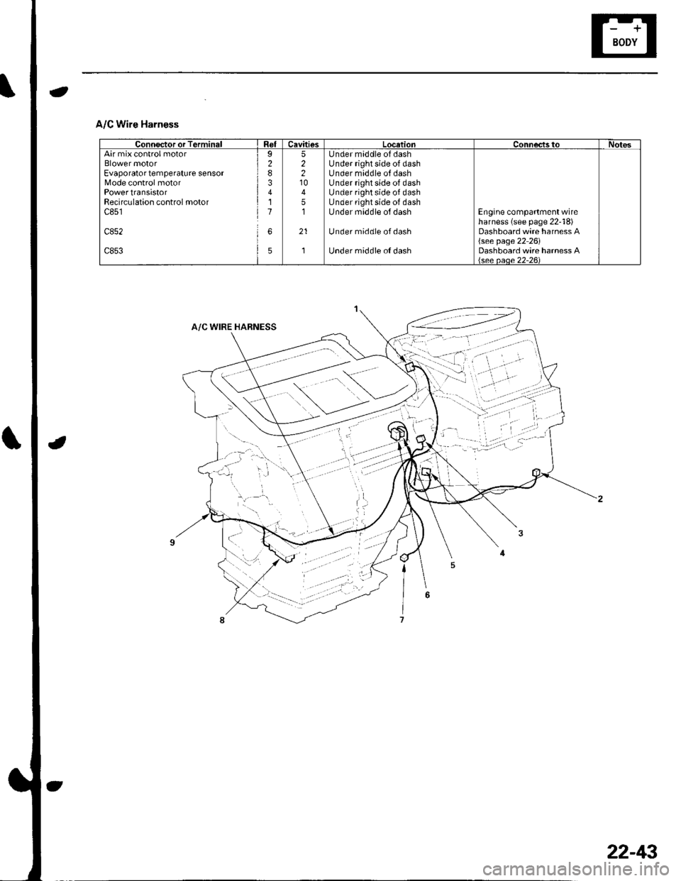
A/C Wire Harness
Connoctor or TerminalRelCavitiesLocationConnec'tstoNotesAir mix control motorBlower motorEvaporator temperature sensorMode control motorPowertransistorRecirculation control motorc851
c852
c853
I283411
6
5
52210
51
21
,]
Under maddle of dashUnder right side of dashUnder middle of dashUnder right side of dashUnder right side of dashUnder right side of dashUnder middle ol dash
Under middle ofdash
Under middle o{ dash
Engine compartment wireharness (see page 22-18)Dashboard wire harness A{see page 22 26iDashboard wire harness Alsee oaoe 22-261
22-43
Page 876 of 1139
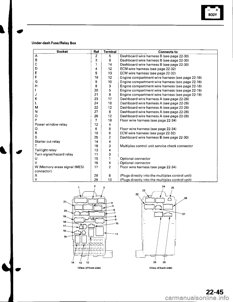
Under-dash Fuse/Relay Box
SocketRefTerminal Connects to
B
c
D
E
F
G
H
J
K
M
N
o
P
Power window relay
o
R
S
Starter cut relay
T
Taillight relay
Turn signal/hazard relay
U
W (Memory erase signal (MES)
connector)
X
Y
2
3
1
5
19
9
I
20
24
22
27
26
7
6
10
25
14
18
11
l5
to
17
28
5
6
14
13
12
10
3
:
11'10
1:
.o^
;;
4
8
2
i
nl
al
lt
2
Dashboard wire harness B {see page 22-30)
Dashboard wire harness B {see page 22-30)
Dashboard wire harness B (see page 22-30)
ECM wire harness (see page 22-32)
ECI\4 wire harness (see page 22-32)
Engine compartment wire harness (see page 22-'l8l
Engine compartment wire harness (se e page 22-181
Engine compartment wire harness (see page 22-18)
Engine compartment wire harness (se e page 22-18)
Engine compartment wire harness (see page 22-18)
Dashboard wire harness A (see page 22-26)
Dashboard wire harness A (see page 22-26)
Dashboard wire harness A (see page 22-26)
Dashboard wire harness A (see page 22-26)
Dashboard wire harness A (see page 22-26)
Floor wire harness (see page 22-34)
Floor wire harness (see page 22-34)
ECM wire harness (see page 22-32)
Dashboard wire harness B (see page 22-30)
Multiplex control unit service check connector
Optional connector
Optional connector
Floor wire harness (see page 22-34)
{Plugs directly into the multiplex control(Pluqs directlv into the multiDlex control
unat)
unrl)
I
13
tn--rlI U LI L.] L.Jh--n-UL]L]UL]
I] L] L] LI L]
!3 12
22-45
Page 880 of 1139
Under-dash Fuse/Relay Box
Removal and Installation
SRS components are located in this area. Review the
SRS component locations {see page 23-13) andprecautions and procedures (see page 23-14) in the SRS
section before performing repairs or service.
Removal
1. Make sure you have the anti-theft code for the radio,
then write down the frequencies for the radio's
preset buttons.
2. Disconnectthe battery negative cable, then
disconnect the positive cable, and wait at least
three minutes.
3. Remove the driver's dashboard lower cover (see
page 20-59).
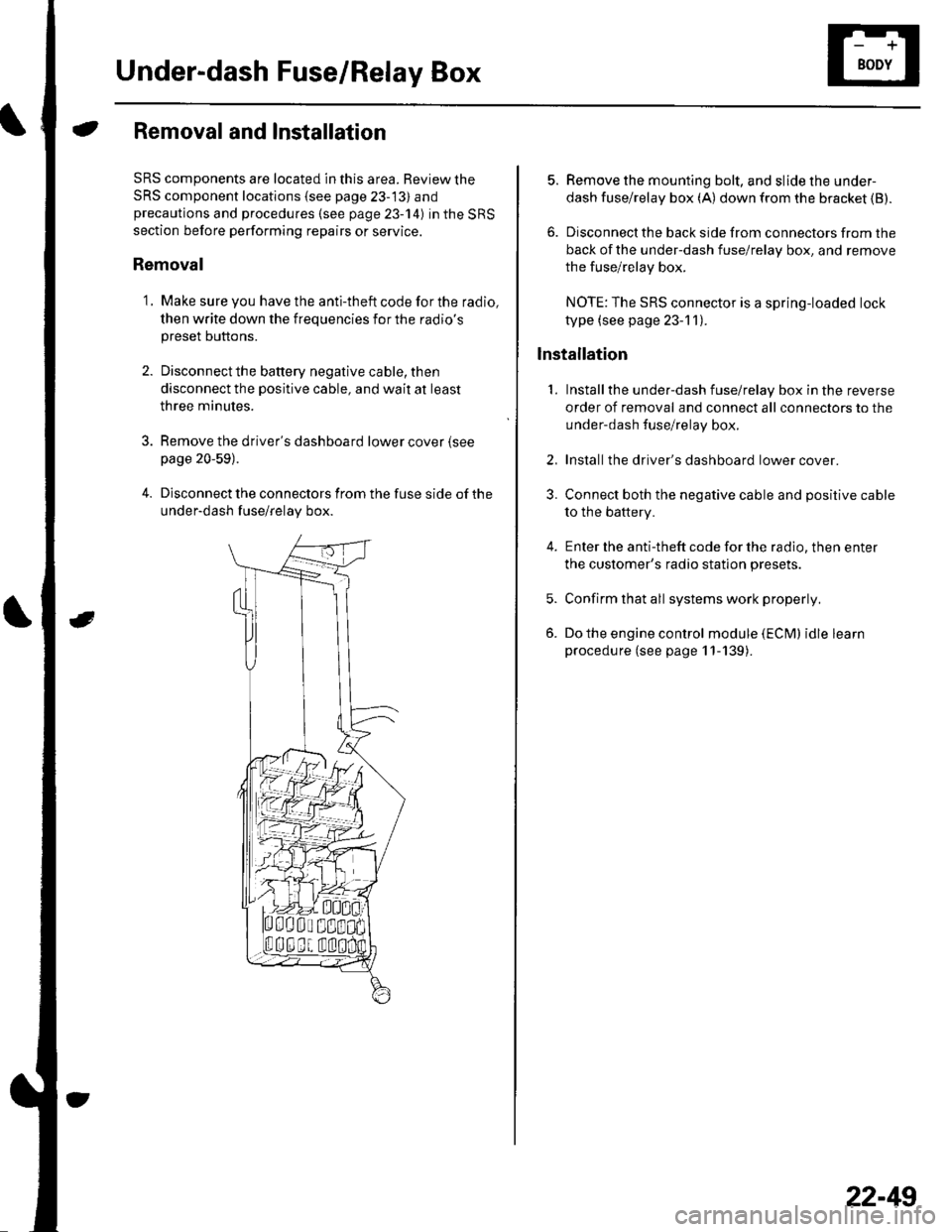
4. Disconnect the connectors from the fuse side of the
under-dash fuse/relay box.
5. Remove the mounting bolt, and slide the under-
dash fuse/relay box (A) down from the bracket {B).
6. Disconnect the back side from connectors from the
back of the under-dash fuse/relay box, and remove
the fuse/relay box.
NOTE:The SRS connector is a spring-loaded lock
type (see page 23-1 1).
lnstallation
1. Installthe under-dash fuse/relay box in the reverse
order of removal and connect all connectors to the
under-dash fuse/relay box.
2. Installthe driver's dashboard lower cover.
3. Connect both the negative cable and positive cable
to the battery.
4. Enter the anti-theft code for the radio, then enter
the customer's radio station presets.
5. Confirm that all systems work properly,
6. Do the engine control module (ECM) idle learn
procedure (see page 11-139).
22-49
Page 884 of 1139
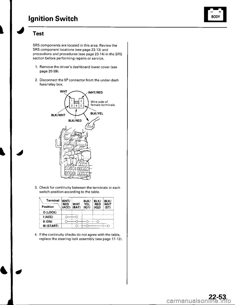
lgnition Switch
Test
SRS components are located in this area. Review the
SRS component locations (see page 23-13) andprecautions and procedures {see page 23-'l4) in the SRS
section before performing repairs or service.
1, Remove the driver's dashboard lower cover {seepage 20-59).
2. Disconnect the 5P connector from the under-dash
fuse/relay box.
WHT/RED
Wire side offemale terminals
BLK/WHTBLK/YEL
BLK/RED
Check for continuity between the terminals in each
switch position according to the table.
Terminal
p.J,i""-\
WHT/RED(ACC)
BLK/WHT YEL(BAT) flGl)
BLK/REDtrc2t
BLK/WHT(sr)
o (LocK)
| (ACC)o---o
[ (oN)
III (START)
c)-_H
o_H
lf the continuity checks do not agree with the table,
replace the steering lock assembly (see page'17-121.
22-53
Page 907 of 1139
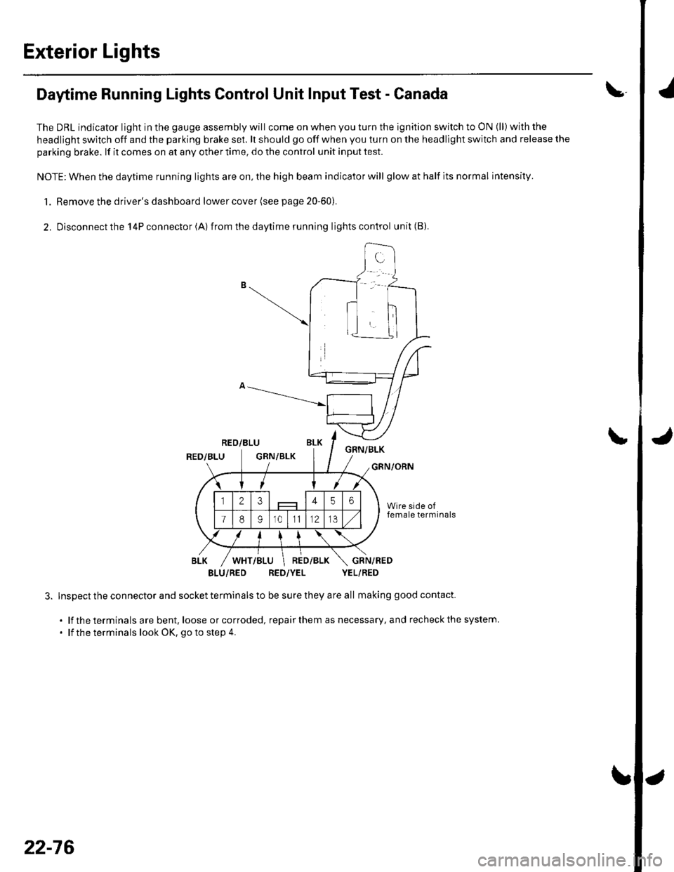
Exterior Lights
Daytime Running Lights Control Unit Input Test - Canada
The DRL indicator light in the gauge assembly will come on when you turn the ignition switch to ON (ll) with the
headlight switch off and the parking brake se1. lt should go off when you turn on the headlight switch and release the
parking brake. lf it comes on at any other time, do the control unit input test.
NOTE: When the daytime running lights are on, the high beam indicator will glow at half its normal intensity.
1. Remove the driver's dashboard lower cover (see page 20-60).
2, Disconnectthe l4Pconnector(A) from thedaytime running lightscontrol unit(B).
RED/BLUGNN/BLKRED/BLUGRN/BLKGRN/ORN
BLU/RED RED/YEL YEL/RED
Inspect the connector and socket terminals to be sure they are all making good contact.
. lf the terminals are bent, loose orcorroded, repairthem as necessary, and recheckthe system.
' lf the terminals look OK, go to step 4.
\
22-76