dashboard HONDA CIVIC 2002 7.G Owner's Guide
[x] Cancel search | Manufacturer: HONDA, Model Year: 2002, Model line: CIVIC, Model: HONDA CIVIC 2002 7.GPages: 1139, PDF Size: 28.19 MB
Page 810 of 1139
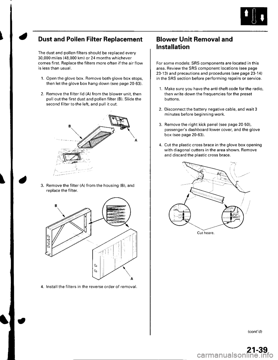
Dust and Pollen Filter Replacement
The dust and pollen filters should be replaced every
30,000 miles (48.000 km) or 24 months whichever
comes first. Replace the filters more often if the air flow
is less than usual.
1. Open the glove box. Remove both glove box stops,
then let the glove box hang down (see page 20 63).
2. Remove the filter lid (A)from the blower unit, then
pull out the first dust and pollen filter (B). Slide the
second filter to the left, and pull it out.
Remove the filter {A) from the housing (B), and
replace the filter.
4. Install the filters in the reverse order of removal.
Blower Unit Removal and
lnstallation
For some models: SRS components are located in this
area. Review the SRS component locations (see page
23-13) and precautions and procedures (see page 23-14)
in the SRS section before performing repairs or service.
1. Make sure you have the anti-theft code for the radio,
then write down the frequencies for the preset
buttons.
2. Disconnect the battery negative cable, and wait 3
minutes before beginning worK.
3. Remove the right kick panel (see page 20-50),
passenger's dashboard lower cover, and the glove
box {see page 20-63).
4. Cut the plastic cross brace in the glove box opening
with diagonal cutters in the area shown. Remove
and discard the plastic cross brace,
Cut heare.
{cont'd)
21-39
Page 815 of 1139
Heating and Air Conditioning
Heater Unit/Core Replacement (cont'd)
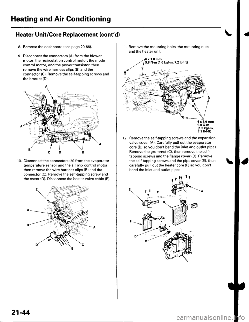
8. Remove the dashboard {see page 20-66).
9. Disconnectthe connectors (A) from the blower
motor, the recirculation control motor, the mode
control motor, and the power transistor, then
remove the wire harness clips (B) and the
connector (C). Remove the self-tapping screws and
the bracket (D).
Disconnect the connectors (A) from the evaporator
temperature sensor and the air mix control motor,
then remove the wire harness clips (B) and the
connector (C). Remove the self-tapping screw and
the cover (D). Disconnect the heater valve cable (E).
10,
7t,
21-44
11. Remove the mounting bolts, the mounting nuts,
and the heater unit.
Remove the self-tapping screws and the expansion
valve cover (A). Carefully pull out the evaporator
core (B) so you don't bend the inlet and outlet pipes.
Remove the grommet (C), then remove the self-
tapping screws and the flange cover (D). Bemove
the self-tapping screws and the pipe cover (E), then
carefully pull out the heater core (F) so you don't
bend the inlet and outlet oioes.
@
5x 1.0 mm9.8 N.m11.0 kgl m,7.2 tbf.ftl
12.
Page 839 of 1139
Relay and Gontrol Unit Locations
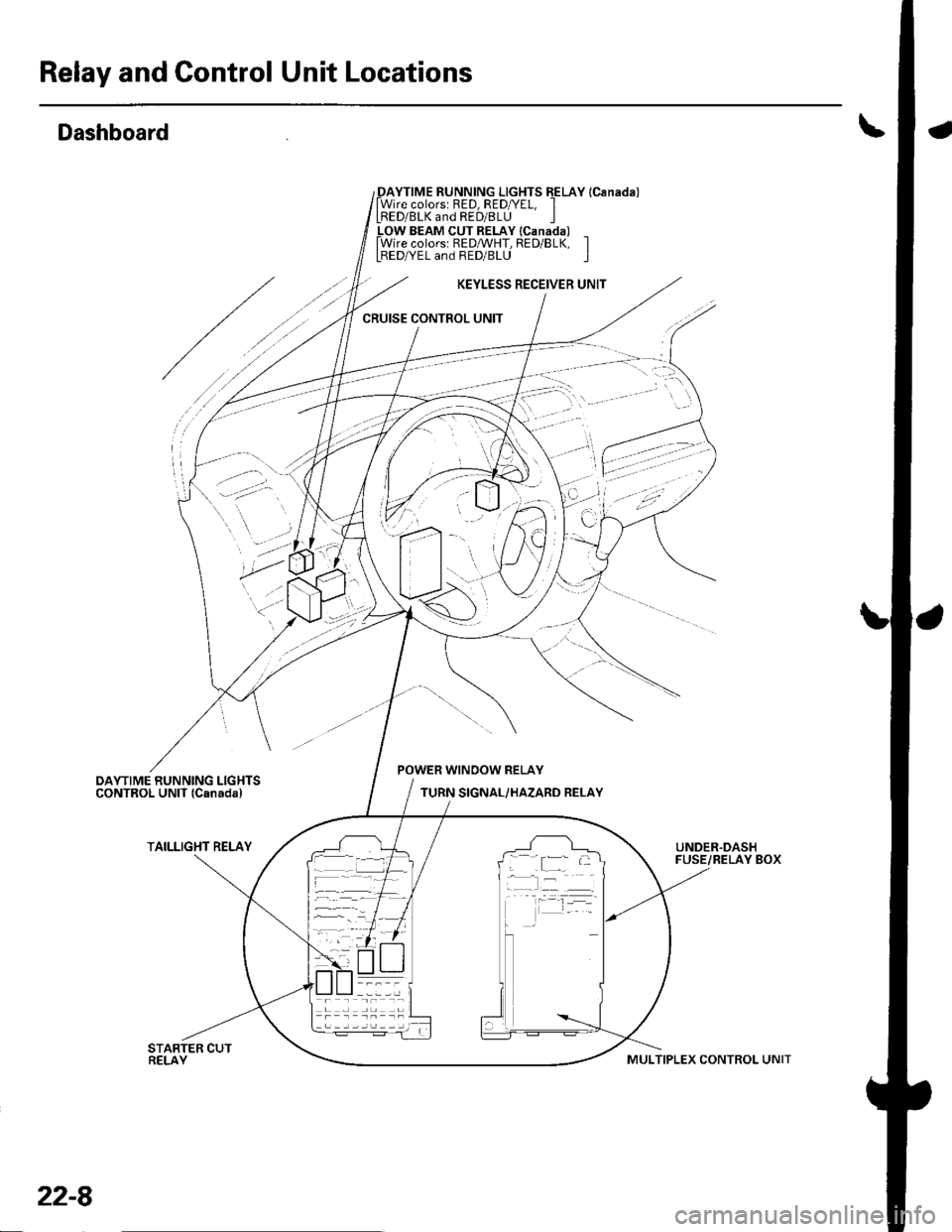
Dashboard
_DAYTIME RUNNING LIGHTS EELAY lCanada)lWire colorsr RED, RED/YEL, ILRED/BLK and RED/8LU I_LOW BEAM CUT RELAY lcanada) _lWire colors: REDMHT, RED/BLK, ILBEDA/EL and RED/BLU I
KEYLESS RECEIVER UNIT
CRUISE CONTROL UNIT
'
'-.:- ':
..? ;,
POWER WINOOW RELAY
TURN SIGNAL/HAZARD RELAY
TAILLIGHT RELAYUNDER.DASHFUSE/RELAY BOX; .[:_- -
-l:r --
22-8
MULTIPLEX CONTROL UNIT
Page 841 of 1139
Relay and Control Unit Locations
a
\
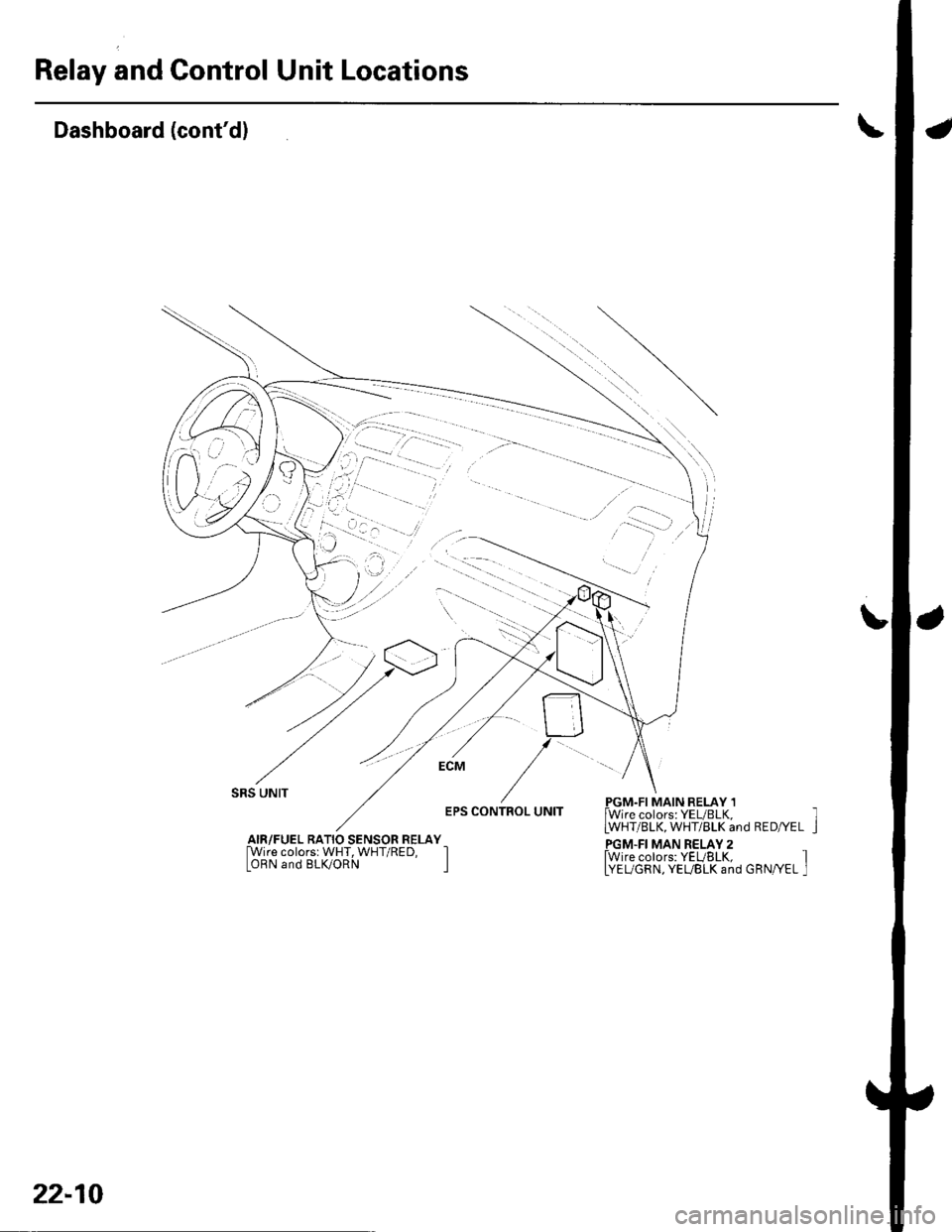
Dashboard (cont'd)
L
SRS UNIT
EPS CONTROL UNITPGM.FI MAIN RELAY 1lWire colors: YEUBLK,LWHT/BLK, WHT/BLK and RED/YEL
PGM.FI MAN RELAY 2fwire colors: YEUBLK, ILYEUGRN, YEUBLK and GRN/YEL I
AIR/FUEL RATIO SENSOR RELAY[Wire colorsr WHT, WHT/RED, IOBN and BLK/ORN I
22-10
Page 844 of 1139
Gonnectors and Harnesses
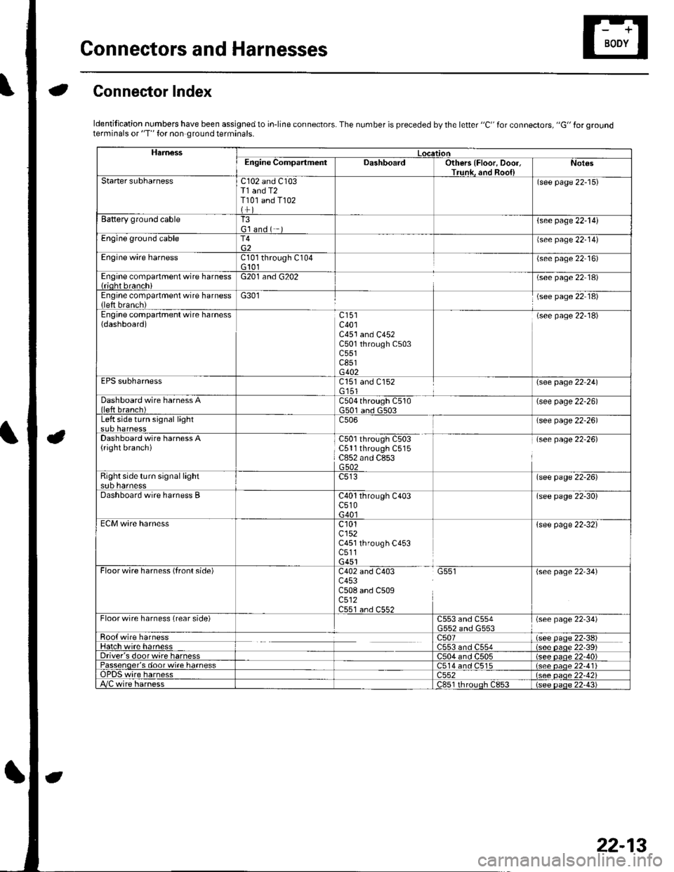
aGonnector Index
ldentification numbers have been assigned to in-line connectors. The number is preceded by the letter "C" for connectors, "G" for groundterminals or "T" for non ground terminals.
HamessLocationEngine CompartmentDashboardOthers {Floor, Door,Trunk. and Roo{lNot€s
Starter subharnessC102 and C103T1 and T2T101 and T102
(see page 22-15)
Battery ground cableT3G'l and ( -{see page 22-l!)
Engine ground cableT4{see page 22-14)
Engine wire harnessCl0l through C104G 101(see page 22 16)
Engine compartment wire harness{rioht branchiG201 and G202(see page 22 18)
Engine compartment wire harness(left brench)G301(see page 22 18)
Engine compartment wire harness(dashboard)c401C451 and C452C501 through C503c551c851G402
(see page 22-18)
EPS subharnessC151 and C152G'151\see page 22 241
Dashboard wire harness Alleft branch)C504 through C510G501 and G503(see page 22-26)
Left side turn signal lightc506(see page 22-26)
Dashboard wire harness A(right branch)C50l through C503C5ll through C515C852 and C853G502
(see page 22-26)
Right side turn si9nal lightsub harnesslsee page 22-26)
Dashboard wire harness BC40l through C403c510G40l
(see page 22-30)
ECM wire harnessc101cl52C451 through C453c511G451
{see page 22-32}
Floorwire harness (front side)C402 and C403 G551c453C508 and C509c512C551 an.l C55?
(see page 22'34)
Floor wire harness (rear side)C553 and C554(see page 22-34)
Roo{ wire harnessc507(see paqe 22-38)Hatch wire harnessC553 and C554(s6e paqe 22'39)Driver's door wire harnessC504 and C505(see paqe 22-40)Passenqer's door wi.e harness514 and C515(see oaoe 22-41Te harness)552(see oaqe 22-42i/C wire harnessc851 rhrouoh c853(see paqe 22.43i
22-13
Page 853 of 1139
Connectors and Harnesses
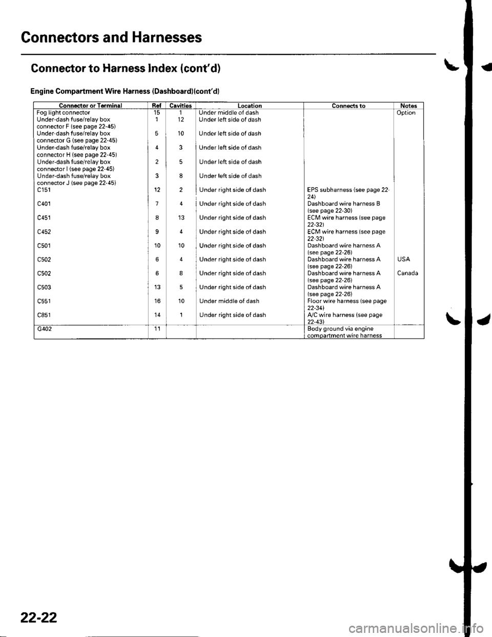
Connector to Harness Index (cont'd)
Engine Compartment Wire Harness (Dashboard)lcont'dl
Connector or TerminalCavitiesLocationConnectstoNotesFog light connectorUnder'dash fuse/relay boxconnector F (see page 22-45)Underdash fuse/relay boxconnector G (see page 22-45)Underdash fuse/relay boxconnector H (see page 22'45)Under-dash fuse/relay boxconnector | (see page 22'45)Under-dash fuse/relay boxconnector J (see page 22-45)c 151
c401
c451
c452
c501
c502
c502
c503
c851'14
2
3
1
I
9
6
6
5
5
12
10
112
10
3
5
8
2
'10
4
8
5
10
1
Under maddle of dashUnder left side of dash
Under left side of dash
Under left side of dash
Under left side of dash
Under left side ol dash
Under right side of dash
Under right side ot dash
Under right side ot dash
Under right side oJ dash
Under right side oI dash
Under right side ol dash
Under right side oJ dash
Under right side oJ dash
Under middle of dash
Under right side of dash
EPS subharness {see page 22-24)Dashboard wire harness B(see page 22-30)ECM wire harness (see page22-321ECM wire harness (seo page22 32)Dashboard wire harness A(see page 22-26)Dashboard wire harness Alsee page 22-261Dashboard wire harness A(see page 22-26)Dashboard wire harness A(see page 22-26)Floorwire harness (see page22-34l',VC wire harness lsee page22-43\
Oplion
Canada
USA
G4021'�IEody ground via engine..mdarlma.t w,rc harncss
22-22
Page 857 of 1139
Connectors and Harnesses
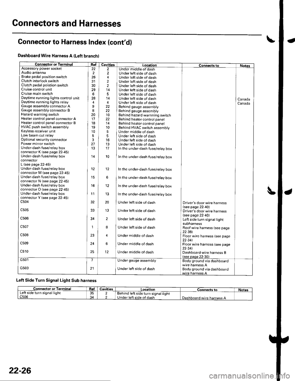
Dashboard Wire Harness A {Left branchl
Connector or TerminalffiAccessory power socketAudio antennaBrake pedal position switchClutch interlock switchClutch pedal poistion switchCruise control unitCruise main switchDaytime r!nning lights control unitDaytime running lights relayGauge assembly connector AGauge assembly connector BHazard warning switchHeater control panel connector AHeater control panel connector BHVAC push switch assemblyKeyless receiver unitLow beam cut relayOptional security connectorPower mirror switchUnder-dash fuse/relay boxconnector K (see page 22-45)Under'dash fuse/relay box
L {see page 22-45}Underdash fuse/relay boxconnector M lsee page 22'45)Under-dash fuse/relay boxconnector N (see page 22-45)UndeFdash fuse/relay boxconnector O (see page 22-45)UndeFdash fuse/relay boxconnectorY (see page 22 45)c504
c505
c506
c507
c508
c509
c510
22226
3029628
I820111819105327
,I4
12
11
34
1
24
25
2 Under middle of dash2 Under left side of dash4 ] Under left side of dash2 ] Under left srde of dash2 | Under left side of dash14 I Under left side of dash5 Under left side of dash14 Under lett side of dash4 Under lett side of dash22 I Behind gauge assembly22 i Behind gauge assembly10 Behind hazard warnning switch22 Behind heater control panel'14 Behind heater control panel10 ] Behind HVAC switch assembly5 I Under middle of dash5 lUnderleftsideofdash16 Under lefr side of dash13 Under left side oI dash17 ln the under-dash fuse/relay box
CanadaCanada
l0In the under-dash fuse/relay box
In the undeFdash fuse/relay box
In the underdash fuse/relay box
In the under-dash fuse/relay box
In the under-dash fuse/relay box
Under left side of dash
Under left side ot dash
Under left side of dash
Under left side of dash
Under middle of dash
Under middle of dash
Under middle ol dash
Driver's door wire harness(see page 22'40)Driver's door wire harness(see page 22-40)Left side turo signal lightsuonarnessRoof wire harness (see page22 3AlFloor wire harness {see page22-341Floor wire harness (see page22 34JDashboard wire harness B(see oaoe 22-30)
12
12
G501
G503
1
21
Under gauge assembly
Under left side of dash
Body ground via dashboard
Body ground via dashboard
Left Side Turn Signal Light Sub harness
Connector to Harness Index (cont'd)
L
Connector or TerminalCavitiesLocationConnects toNolesLeft side turn signal lightc506353422Behind left side turn signal lightUnder left side of dashDashboard wire harness A
22-26
Page 858 of 1139
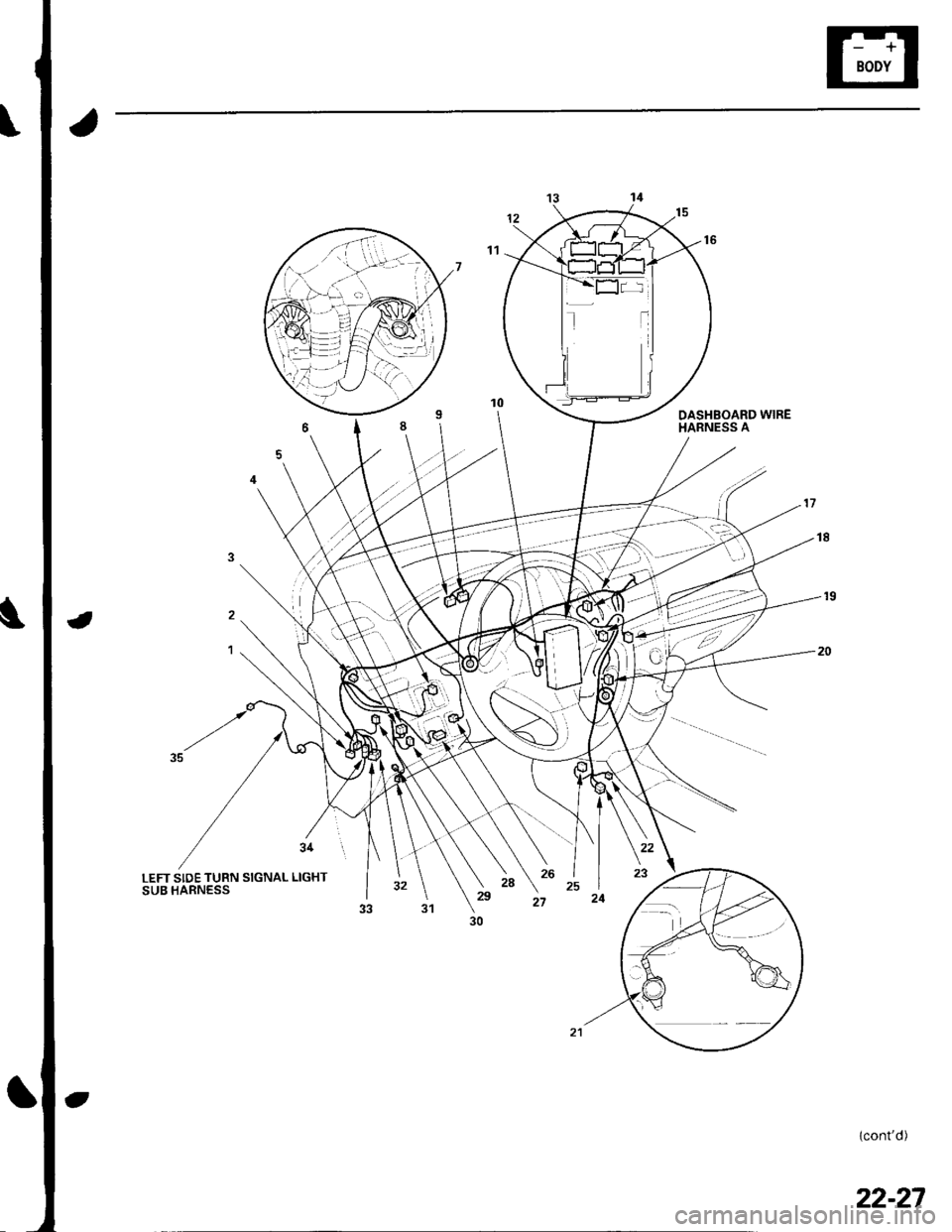
DASHBOARD WIREHARNESS A
,./
-19
20
34 I
LEFT SIDE TURN SIGNAL LIGHTSUB HARNESS). \'u2s )t
30
(cont'd)
22-27
Page 859 of 1139
Connectors and Harnesses
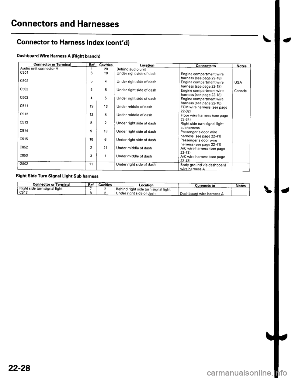
Connector to Harness Index (cont'd)
Dashboard Wire Harness A (Right branch)
Conneclor or TerminalCavitiesLocationConnects toNotesAudio u nit connectorc501
c502
c502
c503
c5'�11
c512
c514
ca52
c8533
9
2
6
5
5
4
12
8
10
2010
4
8
5
8
2
6
21
'l
Eehind audio unitUnder right side of dash
Under right side of dash
Under right side of dash
tJnder right side of dash
Under middle of dash
Under middle of dash
Under right side of dash
Under right side of dash
Under right side of dash
Under middle ofdash
Under middle of dash
Engine compartment wireharness (see page 22,18)Engine companmentwireharness (see page 22-18)Engine compartment wireharness (see page 22-18)Engine compartment wireharness (see page 22- 18)ECN4 wire harness (see page22-321Floor wire harness {see page22-341Right side turn signal lightsuonarnessPassenger's door wireharness (see page 22 4l)Passenger's door wireharness (see page 22 4'l)A,/C wire harness (see page22-43)ly'C wire harness (see page22-431
USA
Canada
G502Under right side of dashEody ground via dashboard
Right Side Turn Signal Light Sub harness
Connector orTorminalCavitiesLocationConnectstoNot€sRight side turn signal lightc5't31822Eehind right side turn signal lightUnder rioht side of dashDashboard wire harness A
22-28
Page 861 of 1139
Connectors and Harnesses
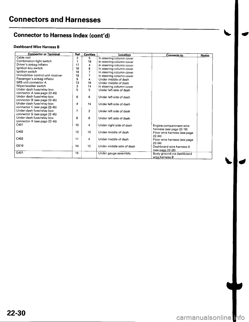
Connector to Harness Index (cont'd)
Dashboard Wire Harness B
Collqctor or TerminalCavitiesLocatiol|ConnectstoNotesCableCombination light switchDriver's airbag inflatorlgnition key switchlgnition switchlmmobilizer control unit receiverPassenger's airbag inf latorSRS unit connector AWiper/washer switchUnder dash fuse/relay boxconnectorA lsee page 22,45)Under dash luse/relay boxconnector B (see page 22-45)Under'dash fuse/relay boxconnector C (see page 22-45)Under-dash fuse/relay boxconnector S lsee page 22-45)Under'dash fuse/relay boxconnectorX (see page 22 45)c401
c402
c403
G510
reel211716't9
18I
35
6
1
8
10
12
11
14
5
4
11418145
6
14
2
8
10
4
12
In steering column coverIn steering column coverIn steering column coverIn steering column coverIn steering column coverIn steering column coverUnder middle of dashUnder middle ofdashIn steering column coverUnder left side of dash
Under left side ofdash
Under left side of dash
Under lett side of dash
Under left side of dash
Under right side of dash
Under middle of dash
Under middle of dash
Under middle side of dash
Engine compartment wireharness (see page 22-'18)Floor wire harness (see page22-34JFloor wire harness (see page22-341Dashboard wire harness A(see oaoe 22-26)G40lUnder gauge assemblyBody ground via dashboard
22-30