check engine HONDA CIVIC 2003 7.G Workshop Manual
[x] Cancel search | Manufacturer: HONDA, Model Year: 2003, Model line: CIVIC, Model: HONDA CIVIC 2003 7.GPages: 1139, PDF Size: 28.19 MB
Page 423 of 1139
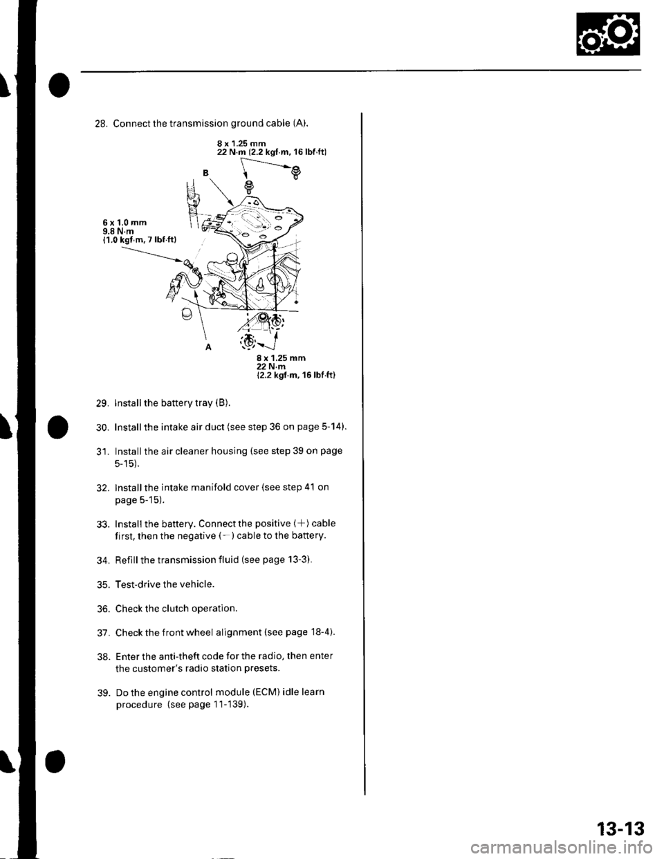
28. Connect the transmission ground cable (A).
8 x 1.25 mm
B
22 N.m (2.2 kgf.m, 16lbf.ft)
[---.-.---e
e
6x1,0mm9.8 N.m{1.0 kgl m. 7 lbf ftl
29.
30.
8x125mm22Nm12.2 kgt m, 16 lbf ft)
lnstall the battery tray (B).
Installthe intake air duct (see step 36 on page 5-14).
Installthe air cleaner housing (see step 39 on page
5-15).
Installthe intake manifold cover (see step 41 on
page 5-15).
Install the battery. Connectthe positive (+) cable
first, then the negative (-)cable to the battery.
Reflllthe transmission fluid (see page 13-3).
Test-drive the vehicle.
Check the clutch operation.
Check the front wheel alignment (see page 18-4).
Enter the anti-theft code for the radio, then enter
the customer's radio station presets.
Do the engine control module (ECM) idle learn
procedure (see page 11-139).
32.
33.
34.
35.
36.
31.
38.
39.
13-13
Page 496 of 1139
Steering
Steering Wheel Rotational Play
Check
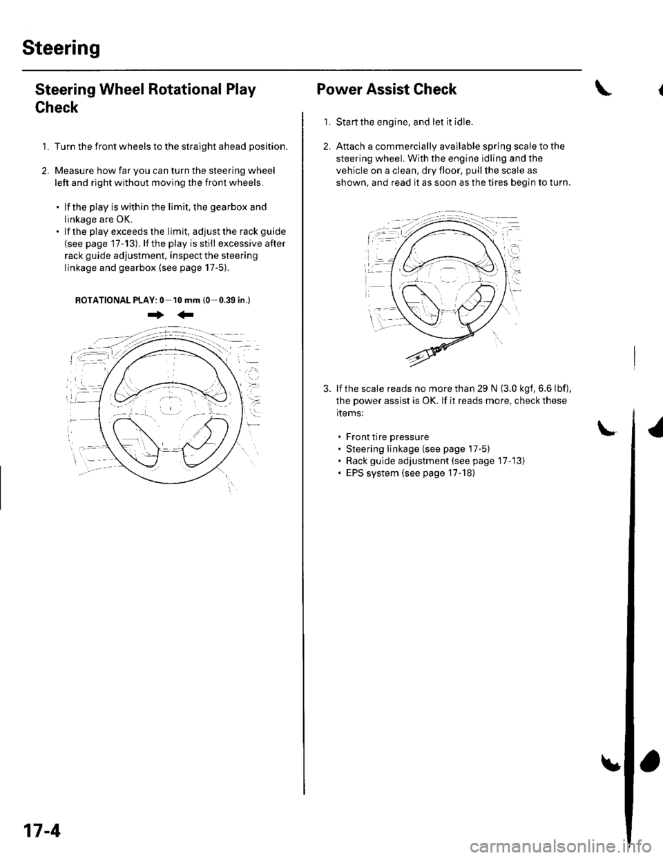
1. Turn the front wheels to the straight ahead position.
2. Measure how far you can turn the steering wheel
left and right without moving the front wheels.
. lf the play is within the limit, the gearbox and
linkage are OK.. lf the playexceedsthe limit, adjustthe rack guide
{see page '17-13). lf the play is still excessive after
rack guide adjustment, inspect the steering
linkage and gearbox {see page 17-5).
BOTATIONAL PLAY: 0 10 mm (0-0.39 in.l
+:
17-4
Power Assist Check
Start the engine, and let it idle.
Attach a commercially available spring scale to the
steering wheel. With the engine idling and the
vehicle on a clean, dry floor, pull the scale as
shown, and read it as soon as the tires begin to turn.
\
1.
3. lf the scale reads no morethan 29 N (3.0 kgf,6.6 lbf),
the power assist is OK. lf it reads more, check these
items:
. Front tire pressure. Steering linkage (see page 17-5). Rack gulde adjustment (see page 17-13). EPS system (see page 17-18)
Page 500 of 1139
Steering
Steering Wheel Installation
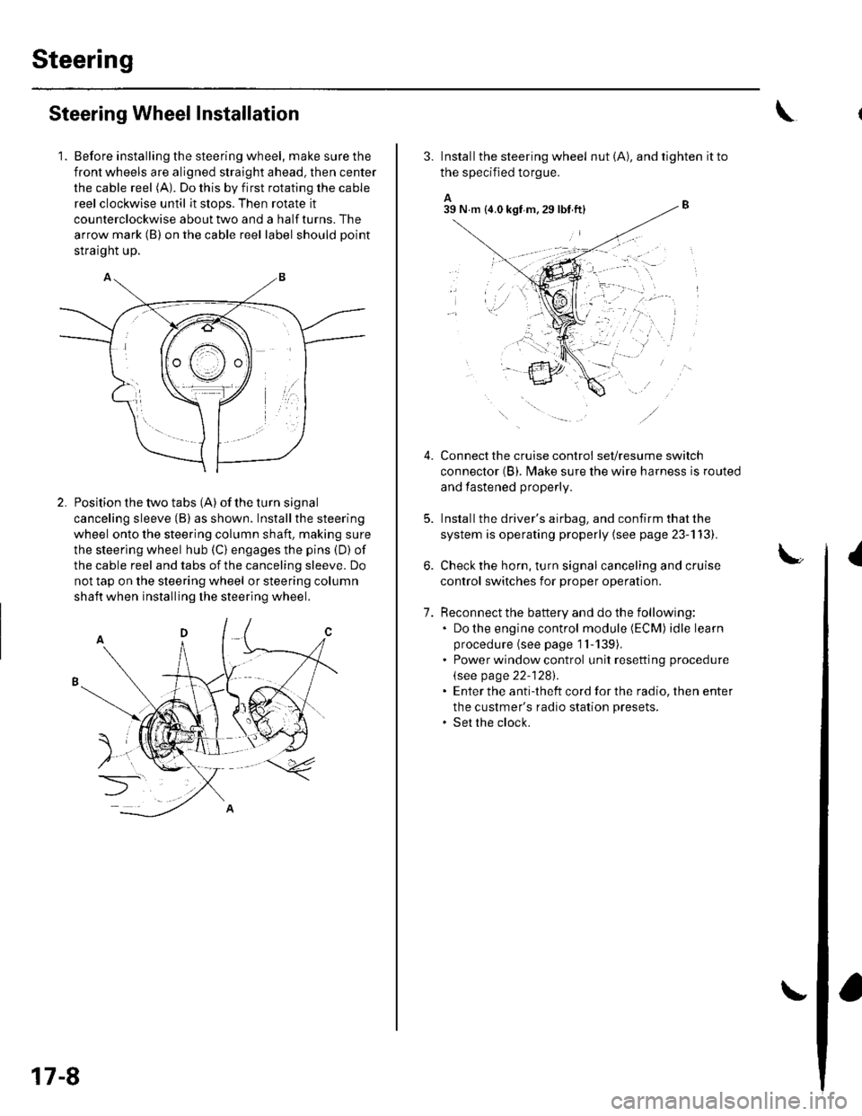
1. Before installing the steering wheel, make sure the
front wheels are aligned straight ahead, then center
the cable reel (A). Do this by first rotating the cable
reel clockwise until it stops. Then rotate it
counterclockwise about two and a half turns. The
arrow mark (B) on the cable reel label should point
straight up.
Position the two tabs (A) of the turn signal
canceling sleeve (B) as shown. Installthe steering
wheel onto the steering column shaft, making sure
the steerlng wheel hub (C) engages the pins (D) of
the cable reel and tabs of the canceling sleeve. Do
not tap on the steering wheel or steering column
shaft when installing the steering wheel.
17-8
3. Install the steering wheel nut (A), and tighten it to
the specified torgue.
A_B39 N.m (4.0 kgf m.29lbt ftl
Connect the cruise control set/resume switch
connector (B). fvlake sure the wire harness is routed
and fastened properly.
Install the driver's airbag, and confirm that the
system is operating properly {see page 23-113).
Check the horn, turn signal canceling and cruise
control switches for proper operation.
Reconnect the battery and do the following:. Do the engine control module (ECM) idle learn
procedure (see page 1l-139),. Power window control unit resetting procedure
\see page 22-1281.. Enter the anti-theft cord for the radio, then enter
the custmer's radio station presets.. Set the clock.
{
7.
lr,',,t
;. _,:!
'' '1i::..'.' l
Page 502 of 1139
Steering
Steering Column Removal
lnstallation
1.
4.
Install the steering column, and make sure the
wires are not caught or pinched by any parts.
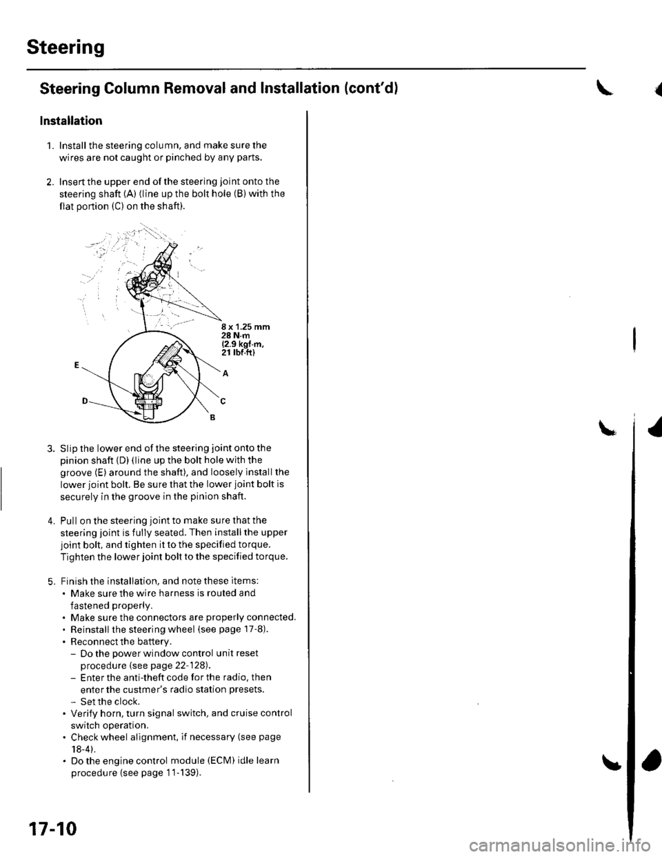
Insertthe upper end ofthe steering joint onto the
steering shaft {A) (line up the bolt hole (B) with the
flat portion (C) on the shaft).
8 x 1,25 mm28 N.m{2.9 kgf m,21 rbr.ft)
A
Slip the lower end of the steering joint onto the
pinion shaft {D) (line up the bolt hole with the
groove (E) around the shaft), and loosely lnstallthe
lower joint bolt. Be sure that the lower joint bolt is
securely in the groove in the pinion shaft.
Pull on the steering joint to make su re that the
steering joint is fully seated. Then installthe upper
joint bolt, and tighten it to the specified torque.
Tighten the lower joint bolt to the specified torque.
Finish the installation, and note these items:
. Make sure the wire harness is routed and
fastened properly.
. Make sure the connectors are properly connected.. Reinstallthe steering wheel (see page 17-8).
. Reconnect the battery.- Do the power window control unitreset
procedure {see page 22-128).- Enter the anti-theft code for the radio, then
enter the custmer's radio station presets.
- Set the clock.. Verify horn, turn signal switch, and cruise control
switch operation.. Check wheel alignment, if necessary (see page
18-4).. Do the engine control module (ECM) idle learn
procedu re {see page '11-139).
17-10
and Installation (cont'd){
Page 516 of 1139
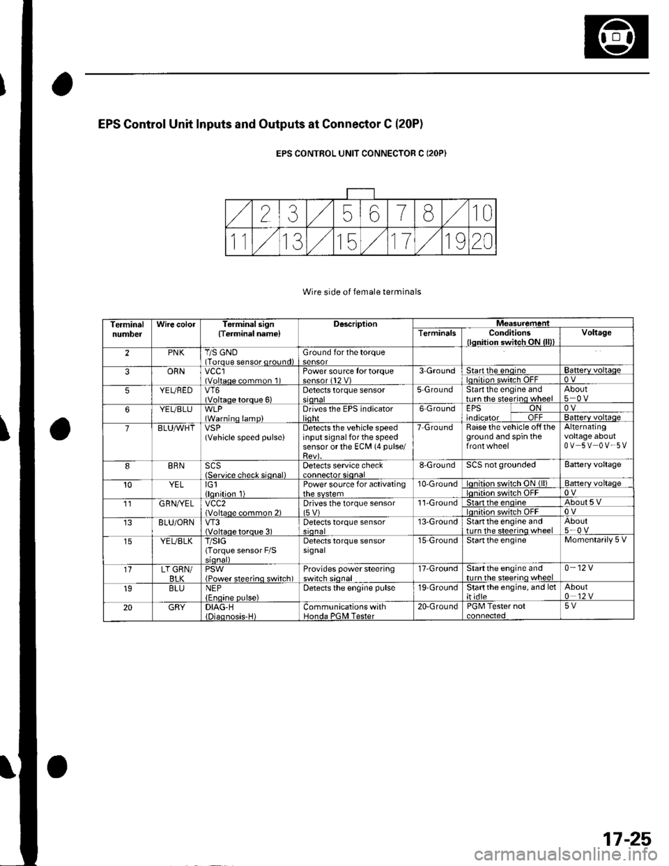
EPS Gontrol Unit Inputs and Outputs at Connestor C (20P1
EPS CONTROL UNIT CONNECTOR C (2OP)
Wire side of female terminals
TerminalnumbelWire colorTerminal sign{Terminel name}DescriplionMeasuremeniTerminalsConditions{lqnition switch ON {lll)Voltage
2PNKT/S GND(Torque sensor qround)Ground for the torque
ORNvccl(Voltaqe common 1Power source fortorque3-Groundtartthe enqrneBa$erv voltaqeOV
5YEUBEDVT6(Voltaqe torque 6)Detects torque sensorstonal5 GroundStartthe engine andturn the steerino wheelAbout
YEUBLU(Warninq lamp)Drives the EPS indicatorlidhr6 GroundEPS ONtnotcatol uTl-OVBanerv voltaqe
7BLUAVHTVSP(Vehicle speed pulseiDetects the vehicle speedinput signal for the speedsensor or the ECM (4 pulse/
Raise the vehicle off theground and spin theAlternatingvoltage aboutOV 5V OV-5V
BRNSCS{Servjco check siqnal)Detects service check8-GroundSCS not groundedBattery voltage
10YELIG1llqnition 1Power source for activating10-Groundon switch ON (ll)Batterv voltaqeon switch OFF11G RN//ELvcc2(Voltaqe common 2)Drives the torque sensor1'l-Groundtan the enoineAbout5Von switch OFF8LU/ORNVT3(Voltaoe toroue 3)Detects torque sensor13-GroundStartthe engine andtrrrn the steerino wheelAbout5-0 v
YEUBLKT/SIG(Torque sensor F/SDetects torque sensorsrgnal15-GroundStartthe engineMomentarily 5 V
1'lLT GRN/BI KPSWiPower steerino switch)Provides power steeringswitch sionall7-GroundStartthe engine andnrrn the steerino wheel0-12V
19BLUNEPDetects the engine pulse19-GroundStartthe engine, and let;t idte
20GRYDIAG-HCommunications withHonda PGNI Tester20-GroundPGM Tester not5V
17-25
Page 519 of 1139
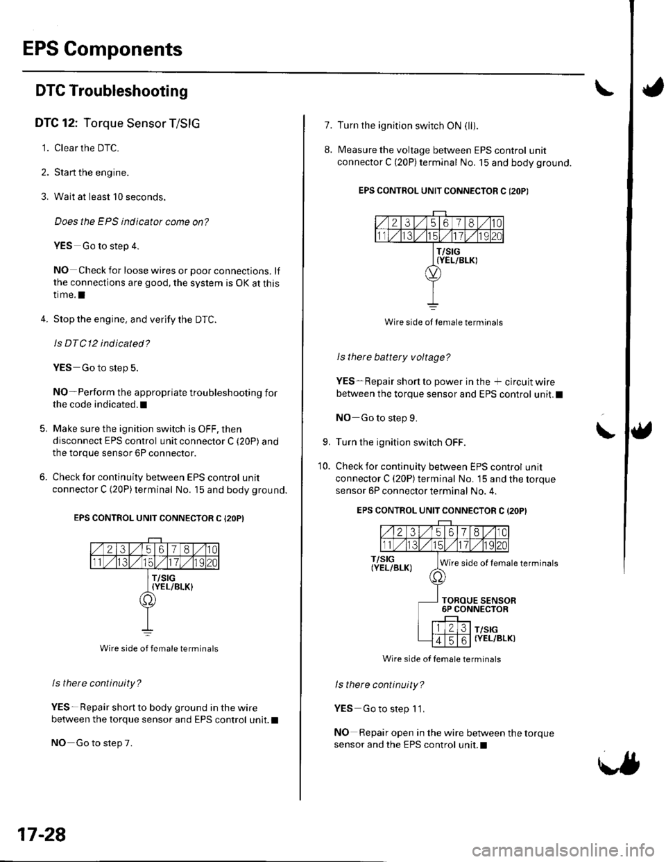
EPS Components
DTC Troubleshooting
DTC 12: Torque Sensor T/SIG
1. Clear the DTC.
2. Stan the engine.
3. Wait at least 10 seconds.
Does the EPS indicatot come on?
YES Go to step 4.
NO Check for loose wires or poor connections. lf
the connections are good, the system is OK at this
time.l
4.Stop the engine, and verify the DTC.
ls DTC12 indicated?
YES Go to slep 5.
NO-Perform the appropriate troubleshooting for
the code indicated. t
Make sure the ignition switch is OFF, then
disconnect EPS control unit connector C (20P) and
the torque sensor 6P connector.
Check for continuity between EPS control unit
connector C (20P)terminal No. 15 and body ground.
EPS CONTROL UNIT CONNECTOR C {2OP)
Wire side of female terminals
ls there continuity?
YES- Repair short to body ground in the wire
between the torque sensor and EPS control unit.l
NO Go to step 7.
5.
17-28
1.
8.
Turn the ignition switch ON (ll).
Measure the voltage between EPS control unit
connector C (20P)terminal No. 15 and body ground.
EPS CONTROL UNIT CONNECTOR C (2OP)
2356180
T/SIG{YEL/BLK)
Wire side ot lemale terminals
I s there battery v oltage?
YES-Repair short to power in the + circuit wire
between the torque sensor and EPS control unit.l
NO Go to step 9.
Turn the ignition switch OFF.
Check for continuity between EPS control unit
connector C (20P) terminal No. 15 and the torque
sensor 6P connector terminal No. 4.
EPS CONTROL UNIT CONNECTOR C (2OPI
\9.
10.
T/SIG(YEL/BLK)Wire side of female terminals
TOROUE SENSOR6P CONNECTOR
T/SIG(YEL/BLK)
ls there continuity?
YES Go to step 1'1,
NO Repair open in the wire between the torque
sensor and the EPS control unit.I
Wire side ot female terminals
Page 520 of 1139
'I 1.Substitute a known-good EPS control unit, and
connect the all disconnected connectors.
Sta rt the engine.
Does the EPS indicator come on?
YES Go to step 13.
NO Check for loose EPS control unitconnectors. lf
necessary, replace the EPS control unit and
retest.l
Stop the engine, and verify the DTC.
ls DTCl2 indicated?
YES Check for loose torque sensor connectors.
lf necessary, substitute a known-good steering
gearbox and recheck.l
NO-Perform the appropriate troubleshooting for
the code indicated. !
12.
13.
DTC 16: Torque Sensor VT3 and W6
1. Clear the DTC.
2. Start the engine.
3. Wait at least 10 seconds.
Does the EPS indicator come on?
YES Go to step 4.
NO Check for loose wires or poor connnections. lf
the connections are good, the system is OK at this
time.l
4. Stop the engine, and verify the DTC.
ls DTC16 indicated?
YES-Go to step 5.
NO Perform the appropriate troubleshooting for
the code indicated. t
5. Make sure the ignition switch is OFF, then
disconnect EPS control unit connector C (20P) and
the torque sensor 6P connector.
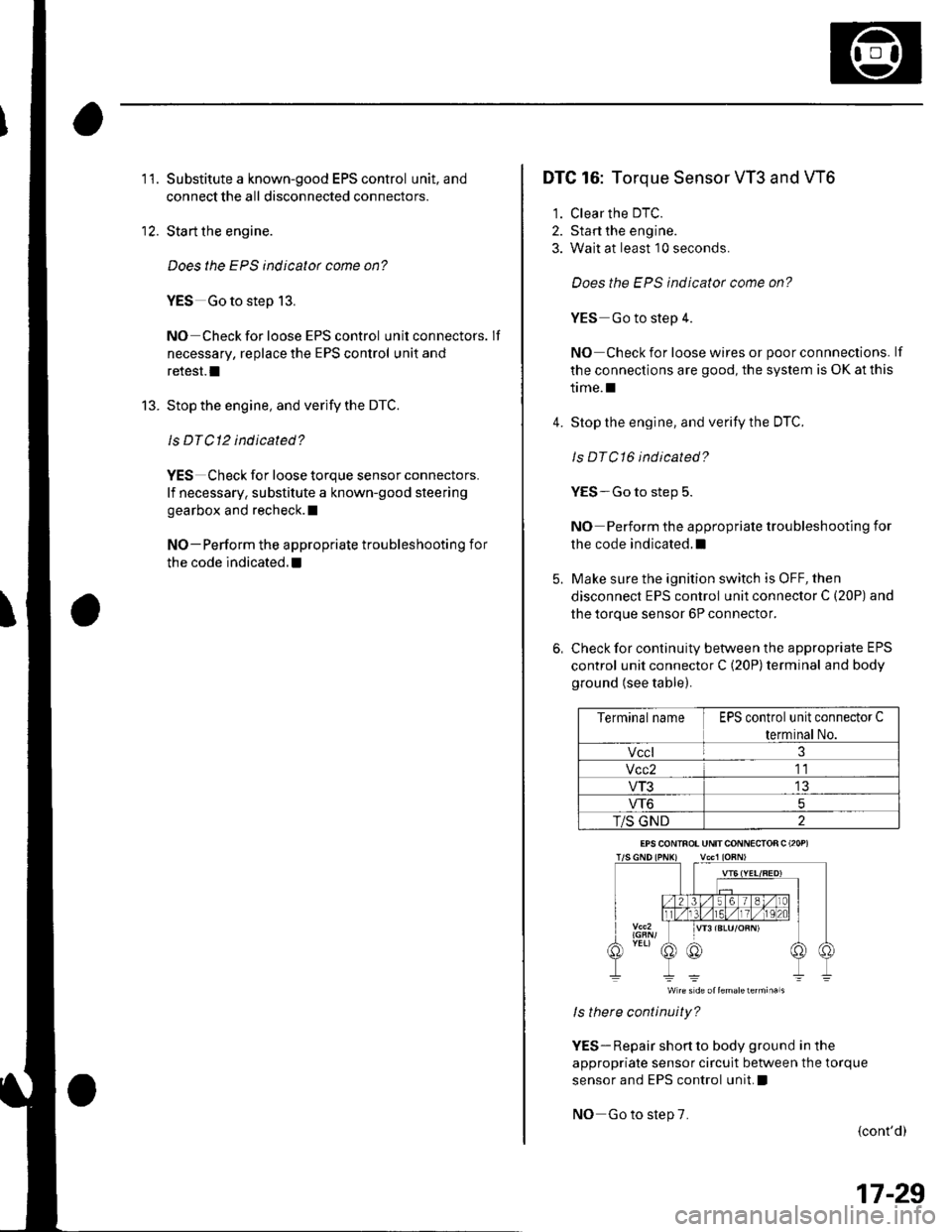
6, Check for continuity between the appropriate EPS
control unit connector C (20P) terminal and body
ground (see table).
Terminal nameEPS control unit connector C
terminal No.
Vccl3
Vcc211
VT313
VT65
T/S GND2
W re s d€ oltemalelermi.als
ls there continuity?
YES- Repair short to body ground in the
appropriate sensor circuit between the torque
sensor and EPS control unit, !
NO Go to step 7.
{cont'd)
EPS CONINOT UNITCONNECIOR C (2OP)
17-29
Page 522 of 1139
11.
't2.
Substitute a known-good EPS control unit, and
reconnect the disconnected connectors.
Sta rt the engine.
Does the EPS indicator come on?
YES Go to step 13.
NO Check for loose or poor connections at the
EPS control unit and the torque sensor conneclors.
lf the connections are good, replace the EPS control
unit and recheck.I
Stop the engine, and verify the DTC.
ls DTC16 indicated?
YES Replace the steering gearbox and recheck.l
NO Perform the appropriate troubleshooting for
the code indicated.l
13.
DTC 17: Torque Sensor Vccl
DTC 18: Torque Sensor Vcc2
1. Clear the DTC.
2. Start the engine.
3. Wait at least 10 seconds.
4.
Does the EPS indicator come on?
YES Go to step 4.
NO Check for loose wires or poor connections. lf
the connections are good, the system is OK at this
time.I
Stop the engine, and verify the DTC.
Is DTCl7 or DTCl8 indicated?
YES Go to step 5.
NO Do the troubleshooting for the DTc
indicated.I
Make sure the ignition switch is OFF, then
disconnect EPS control unit connector C (20P) and
the torque sensor 6P connector.
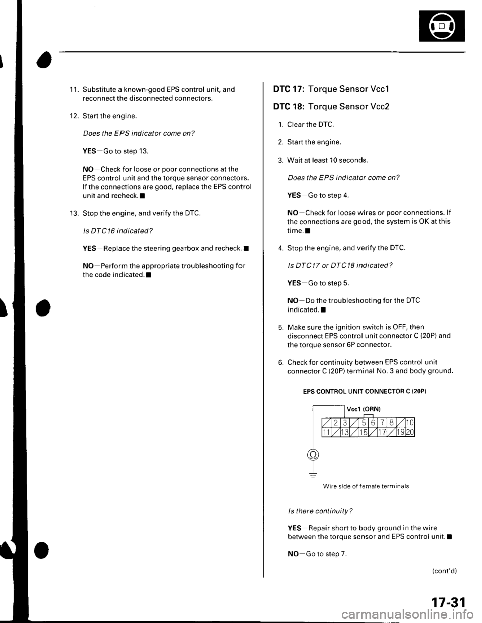
Check for continuity between EPS control unit
connector C (20P)terminal No. 3 and body ground.
EPS CONTROL UNIT CONNECTOR C (2OP)
Wire side o{ female terminals
ls there continuity?
YES Repair shon to body ground in the wire
between the torque sensor and EPS control unit.I
NO Go to step 7.
(cont'd)
17-31
Page 523 of 1139
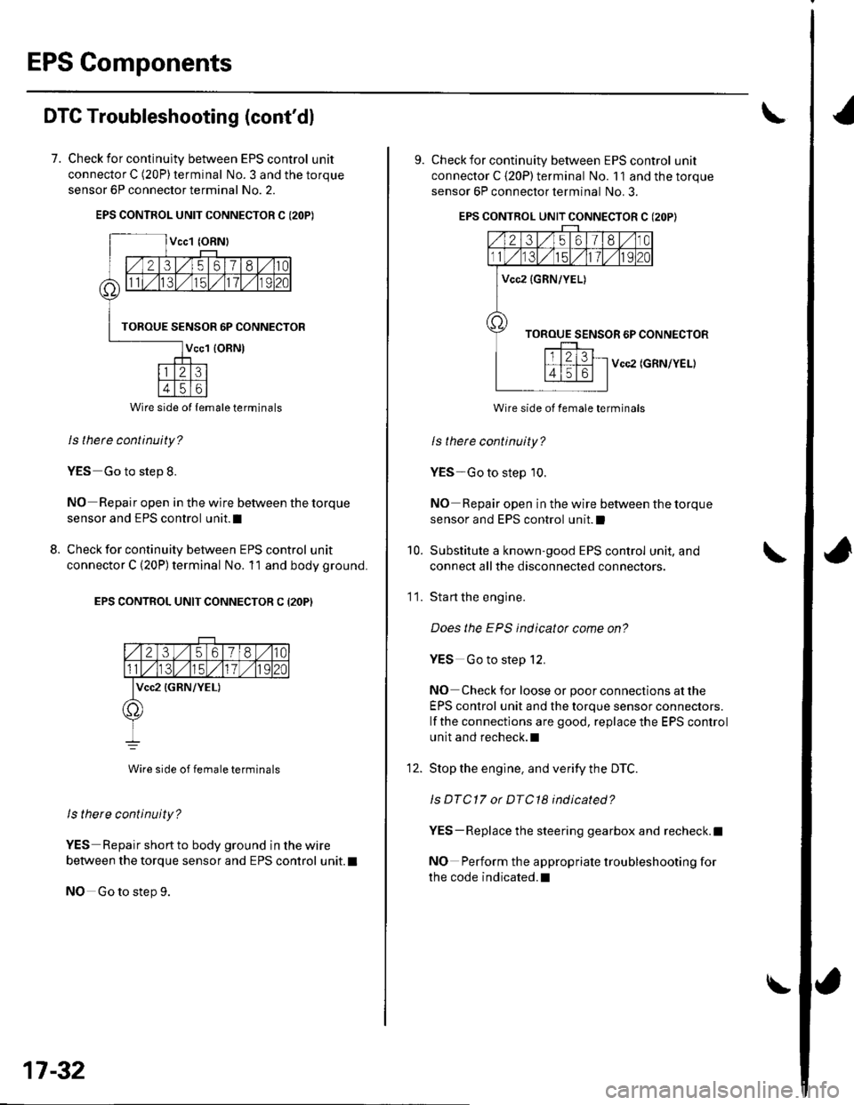
EPS Components
DTC Troubleshooting (cont'dl
7. Check for continulty between EPS control unit
connector C (20P) terminal No. 3 and the torque
sensor 6P connector terminal No. 2.
EPS CONTROL UNIT CONNECTOR C I2OP)
ls thete continuity?
YES Go to step 8.
NO Repair open in the wire between the torque
sensor and EPS control unit.I
Check for continuity between EPS control unit
connector C (20P) terminal No. 11 and body ground.
EPS CONTROL UNIT CONNECTOR C (2OP)
2356180
lvcc2 {GRN/YEL)
Wire side of female terminals
ls there continuity?
YES Repair short to body ground in the wire
between the torque sensor and EPS control unit. t
NO Go to step 9.
8.
Wire side ol lemale terminals
17-32
\
9. Check for continuity between EPS control unit
connector C {20P) terminal No. 11 and the torque
sensor 6P connector terminal No. 3.
EPS CONTROL UNIT CONNECTOR C (2OP}
Vcc2 (GRN/YEL)
Wire side of female terminals
ls therc continuity?
YES-Go to step 10.
NO Repair open in the wire between the torque
sensor and EPS control unit.l
Substitute a known-good EPS control unit, and
connect all the disconnected connectors.
Sta rt the engine.
Does the EPS indicator come on?
YES Go to step 12.
NO Check for loose or poor connections at the
EPS control unit and the torque sensor connectors.
lf the connections are good, replace the EPS control
unit and recheck.l
Stop the engine, and verity the DTC.
ls DTC17 or DTC18 indicated?
YES-Replace the steering gearbox and recheck.l
NO Perform the appropriate troubleshooting for
the code indicated.l
10.
11.
12.
Page 524 of 1139
DTC 22: Vehicle Speed Sensor Signal
DTC 23: Engine Speed Signal
NOTE:. lf the MIL indicator is ON, troubleshoot the PGIVI-Fl
system first.. Even though the system is operating normally, the
EPS indicator will come on under the following
conditions.
- Condition 1:. The vehicle was traveling at least '12.4 mph(20 km/h), then. A rapld change in vehicle speed was detected,
then. The vehicle (or the vehicle speed sensor signal)
stopped for at least 5 seconds, and. The engine speed was still 1,640 rpm or higher for
at least 5 seconds- Condition 2:
After the vehicle (or the vehicle speed sensor
signal) has stopped for at least 10 seconds, yetthe
engine speed was still 1,640 rpm or higher for at
least 20 seconds.- Condition 3:
When the vehicle speed is 10 km/h (6.2 mph) or
above and the engine is running at 280 rpm or
below for 3 seconds.
1. Start the engine and check the tachometer.
ls the tachometer working correctly?
YES- Go to step 2.
NO-Go to step 9.
2. Test-drive the vehicle above 15 km/h {9.3 mph).
ls the speedometer working correctly?
YES Go to step 3.
NO-Perform the speedometer system
troubleshooting {see page 22-651.a
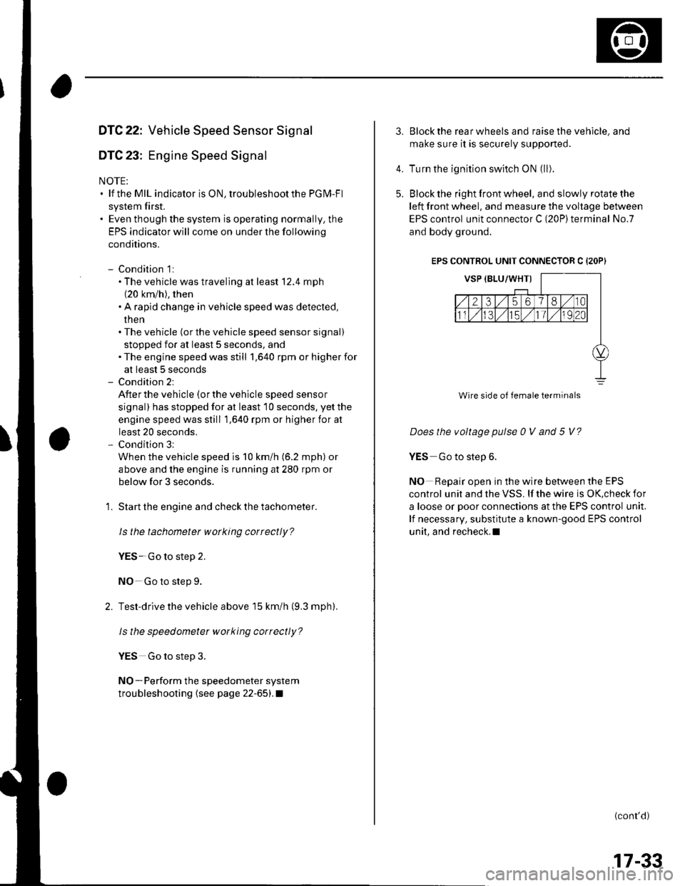
3.Block the rear wheels and raise the vehicle, and
make sure it is securely supported.
Turn the ignition switch ON (ll).
Block the right front wheel, and slowly rotate the
left front wheel, and measure the voltage between
EPS control unit connector C (20P)terminal No.7
and body ground.
EPS CONTROL UNIT CONNECTOR C {2OP)
Does the voltage pulse 0 V and 5 V?
YES Go to step 6.
NO Repair open in the wire between the EPS
control unit and the VSS. lf the wire is OK,check for
a loose or poor connections at the EPS control unit.
lf necessary, substitute a known-good EPS control
unit, and recheck.l
(conr'd)
4.
5.
Wire side of female terminals
17-33