check engine HONDA CIVIC 2003 7.G Manual PDF
[x] Cancel search | Manufacturer: HONDA, Model Year: 2003, Model line: CIVIC, Model: HONDA CIVIC 2003 7.GPages: 1139, PDF Size: 28.19 MB
Page 291 of 1139
PGM-FI System
(
(
DTG Troubleshooting (cont'dl
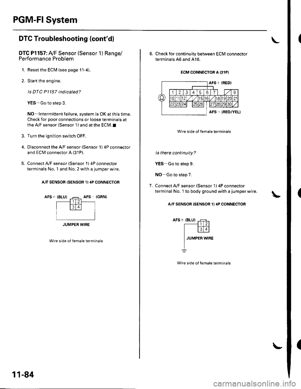
DTC Pl157: Ay'F Sensor (Sensor 1) Range/
Performance Problem
1. Resetthe ECIM (see page 11-4).
2. Start the engine.
ls DTC Pl157 indicated?
YES-Go to step 3.
NO Intermittent failure, system is OK at this time.
Check for poor connections or loose terminals at
the Ay'F sensor (Sensor 1 ) and at the ECN4.I
Turn the ignition switch OFF.
Disconnect the Ay'F sensor (Sensor 1) 4P connector
and ECM connector A (31P).
Connect A,/F sensor (Sensor 1) 4P connector
terminals No. 1 and No. 2 with a jumper wire.
A/F SENSOR (SENSOR 1) 4P CONNECTOR
AFS+ {BLU)
Wire side of female terminals
3.
JUMPER WIRE
11-84
L
6. Check for continuity between ECM connector
terminals 46 and A16.
ECM CONNECTOR A {3IP)
Wire side of female terminals
ls there continuity?
YES Go to step 9.
NO Go to step 7.
Connect A/F sensor (Sensor 1) 4P connecror
terminal No. 1 to body ground with a jumper wire.
A/F SENSOR {SENSOR 1I 4P CONNECTOR
7.
Wire side ot female terminals
Page 292 of 1139
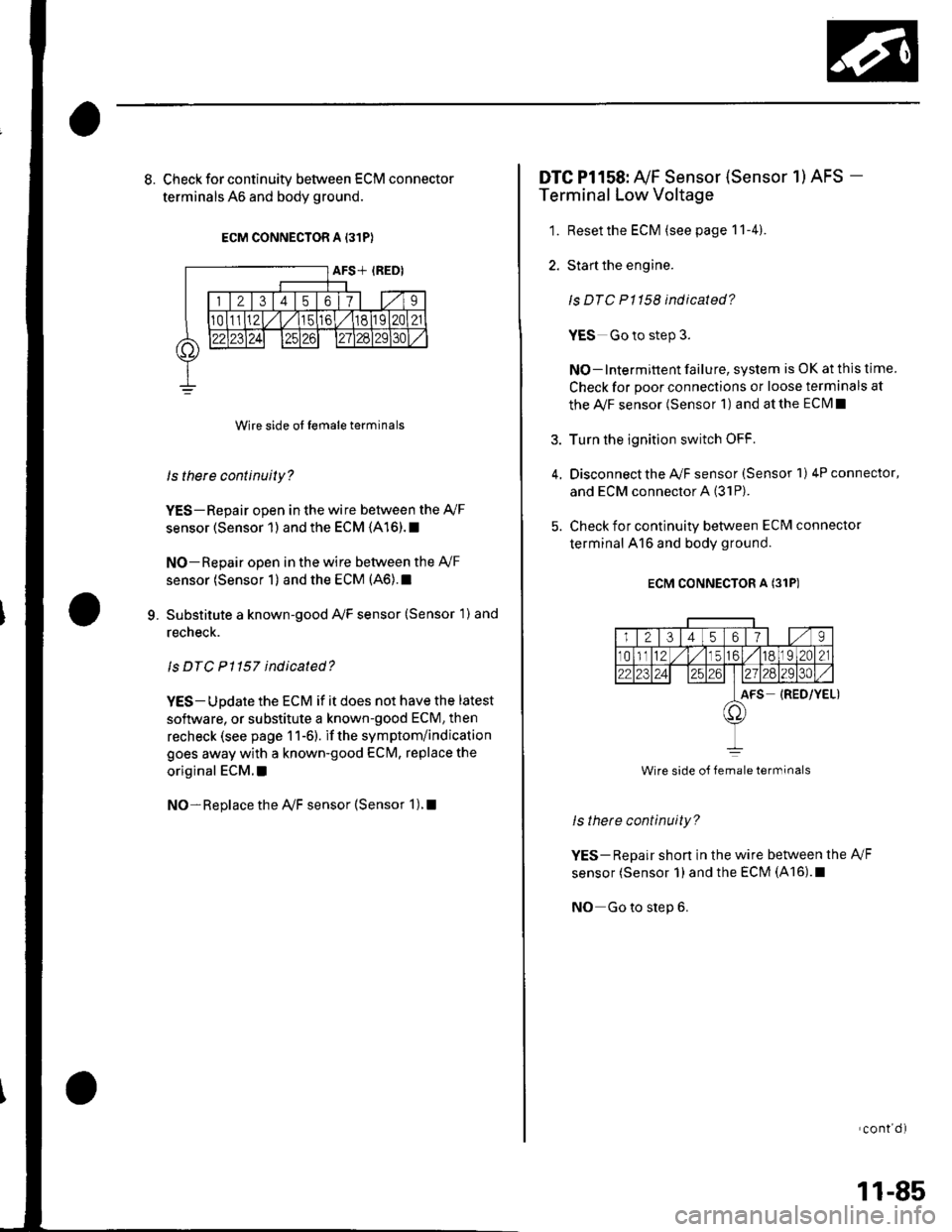
8. Check for continuity between ECM connector
terminals 46 and body ground.
ECM CONNECTOR A 131P}
Wire side ol lemale terminals
ls there continuity?
YES-Repair open in the wire between the Ay'F
sensor (Sensor 1) and the ECM (416).1
NO-Repair open in the wire between the Ay'F
sensor (Sensor 1) and the ECM (46).1
Substitute a known-good Ay'F sensor (Sensor 1) and
recheck.
ls DTC P1157 indicated?
YES- Update the ECM if it does not have the latest
software, or substitute a known-good ECM, then
recheck (see page 1 1-6). if the symptom/indication
goes away with a known-good ECM, replace the
original ECM. !
NO- Replace the Ay'F sensor {Sensor 1). !
9.
DTC Pl158: Ay'F Sensor (Sensor 1) AFS -
Terminal Low Voltage
1. Resetthe ECM (see page 11-4).
2. Start the engine.
ls DTC P1158 indicated?
YES Go to step 3.
NO-lntermittent failure, system is OK at this time
Check for poor connections or loose termanals at
the Ay'F sensor (Sensor 1) and at the ECIM I
3. Turn the ignition switch OFF.
4, Disconnectthe Ay'F sensor (Sensor 1) 4P connector,
and ECM connector A (31P).
5. Check for continuity between ECM connector
terminal 416 and body ground.
ECM CONNECTOR A (31P)
ls thete continuity?
YES-Repair shon in the wire between the A,/F
sensor (Sensor 1)and the ECM (A16).1
NO Go to step 6.
'cont d)
Wire side oJ female terminals
11-85
Page 293 of 1139
PGM-FI System
(
a
DTC Troubleshooting (cont'd)
6. Substitute a known-good Ay'F sensor (Sensor 1)and
recheck.
Is DTC P1158 ind icated?
YES Update the ECM if it does not have the latest
software, or substitute a known-good ECM, then
recheck (see page 1 1-6). if the symptom/indication
goes away with a known-good ECM, replace the
original ECM.I
NO- Replace the Ay'F sensor (Sensor 1). t
11-86
DTC Pl159: A,/F Sensor (Sensor 1) AFS +
Terminal Low Voltage
1. Resetthe ECM (see page 11-4).
2. Sta rt the engine.
ls DTC P1159 ind icated?
YES-Go to step 3.
NO-lntermiftent failure. system is OK at this time.
Check for poor connections or loose terminais at
the A,/F sensor (Sensor 1) and at the ECM.I
3. Turn the ignition switch OFF.
4. Disconnect the Ay'F sensor (Sensor 1) 4P connector
and EcM connector A (31P).
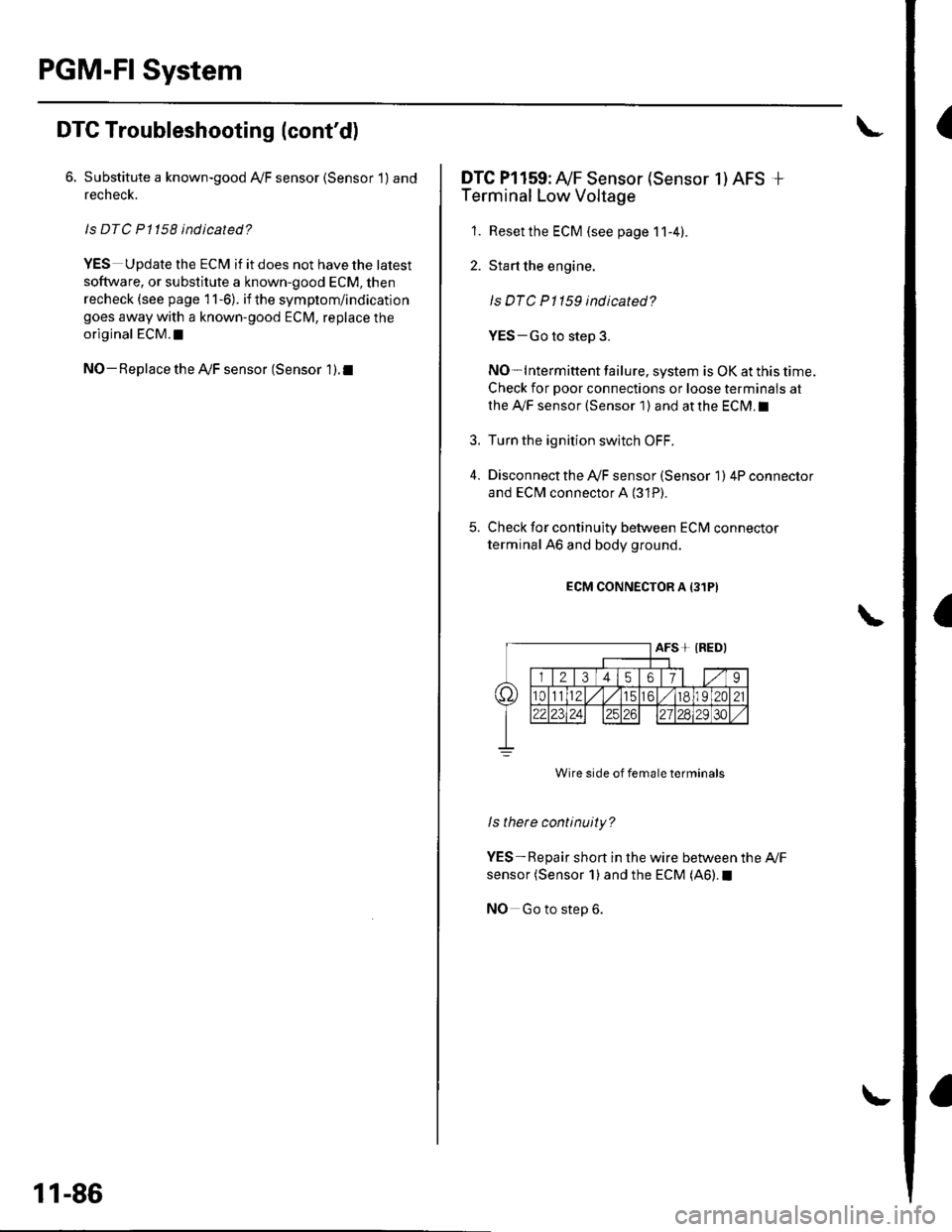
5. Check for continuity between ECM connector
terminal 46 and body ground.
ECM CONNECTOR A {31PI
Wire side of female terminals
ls there continuity?
YES-Repair short in the wire between the Ay'F
sensor (Sensor 1) and the ECM (AO).I
NO Go to step 6.
Page 295 of 1139
PGM-FI System
DTC Troubleshooting (cont'dl
DTC Pl163: Ay'F Sensor (Sensor 1 ) SlowResponse
NOTE: lf DTC P1162 is stored at the same time as DTC
P1163. troubleshoot DTC P1162 first, then recheckfor
DTC P1163.
1. Reset the ECM (see page 1 1-4).
2. Start the engine. Hold the engine at 3,000 rpm with
no load (in neutral) until the radiator fan comes on.
3. Test-drive under the following conditions:
. 55 mph (89 km/h) steady speed' Transmission in sth gear' Until the Ay'F sensor readiness code or
Temporary DTC Pl163 comes on
4. Check for a Temporary DTC with the scan tool.
ls Temporary DTC P 1163 indicated?
YES Replace the Ay'F sensor (Sensor 1).I
NO Intermittent failu re, system is OK at this time.
Check for poor connections or loose terminals at
the A'lF sensor (Sensor 1 ) and at the ECM. t
11-88
DTC Pl164: A,/F Sensor (Sensor 1) Circuit
Range/Performance Problem
1. Resetthe ECI\4 (see page 1t-4).
2. Start the engine. Holdtheengineat3,000 rpmwith
no load (in neutral) until the radiator fan comes on,
3. Test-drive in 3rd gear. Starting at 1,600 rpm,
accelerate using wide open throttle for at least
5 seconds. Then decelerate for at least 5 seconds
with the throttle completely closed until the A,/F
sensor readiness code is set to complete or
Temporary DTC P1 164 comes on.
4. Check for a Temporary DTC with the scan tool.
ls Temporary DTC P1164 indicated?
YES- Replace the A,,/F sensor (Sensor 1). I
NO Intermittent failure, system is OK at this time.
Check for poor connections or loose terminals at
the Ay'F sensor relay, at the Ay'F sensor (Sensor 1),
and at the EcM.l
Page 296 of 1139
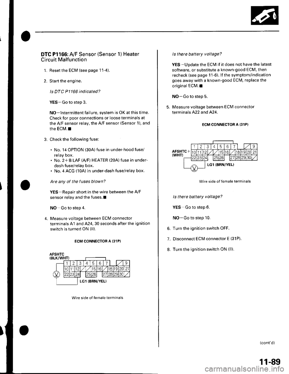
DTC Pl166: Ay'F Sensor (Sensor 1) Heater
Circuit Malfunction
1. Resetthe ECM (see page 11-4).
2. Start the engine.
ls DTC P1166 indicated?
YES-Go to step 3.
NO-lntermittent failure, system is OK at this lime.
Check for poor connections or loose terminals at
the Ay'F sensor relay, the A,/F sensor (Sensor 1), and
the EcM. !
3. Check the following fuse:
. No. 14 OPTION (30A)fuse in under-hood fuse/
reray Dox.. No. 2*B LAF (Ay'F) HEATER (20A) fuse in under-
dash fuse/relay box.. No. 4 ACG (10A) in underdash fuse/relay box.
Are any of the fuses blown?
YES Repair short in the wire between the Ay'F
sensor relay and the fuses.I
NO Go to step 4.
4. Measure voltage between ECM connector
terminals A1 and A24. 30 seconds after the ignition
switch is turned ON (ll).
ECM CONNECTOR A I31P)
Wire srde of lemale terminals
Is therc battery voltage?
YES-Update the ECM if it does not have the latest
soflware, or substitute a known-good ECM. then
recheck (see page 1 1-6). lf the symptom/indication
goes away with a known-good ECM, replace the
original ECM.I
NO-Go to step 5.
5. Measure voltage between ECM connector
terminals A22 and A24.
ECM CONNECTOR A {31P}
Wire side of female terminals
ls there battery voltage?
YES Go to step 6.
NO-Go to step 10.
6. Turn the ignition switch OFF.
7. Disconnect ECM connector E (31P).
8. Turn the ignition switch ON {ll).
(cont'd)
11-89
Page 298 of 1139
DTC Pl167: Ay'F Sensor (Sensor 1) Heater
Circuit Malfunction
NOTE: lf DTC P1162 is stored at the same time as DTC
P1167, troubleshoot DTC P1162 first, then troubleshoot
DTC P1167.
1. Resetthe ECI\4 (see page 11-4)
2. Start the engine. Wait for at least 80 seconds.
ls DTC P01167 ind icated?
YES Go to step 3.
NO-lntermittent failure, system is OK at this time.
Check for poor connections or loose terminals at
the Ay'F sensor relay, at the Ay'F sensor (Sensor 1),
and at the ECM.I
Turn the ignition switch OFF.
Disconnect the A,/F sensor 4P connector and ECM
connector A (31P).
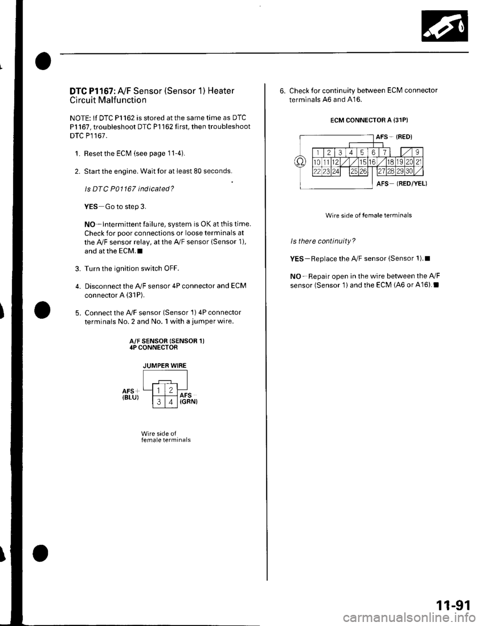
Connect the Ay'F sensor (Sensor 1) 4P connector
terminals No. 2 and No. 1 with a jumper wire.
?
5.
A/F SENSOR (SENSOR 1)4P CONNECTOR
JUMPER WIRE
Wire side offemale terminals
6. Check for continuity between ECM connector
terminals ,46 and 416.
ECM CONNECTOR A {31P)
AFS- {RED)
trTzTil,ils llt9
t82C21
l?rlzsIels
AFSIRED/YEL)
Wire side of lemale terminals
ls thete continuity?
YES-Replace the A/F sensor (Sensor 1).1
NO-Repair open in the wire between the Ay'F
sensor (Sensor 1 ) and the ECM (46 or A16).I
11-91
Page 299 of 1139
PGM-FI System
I
a
DTC Troubleshooting (cont'dl
DTC Pl297: ELD Circuit Low Voltage
1. Reset the ECM {see page 11-4).
2. Start the engine.
3. Turn on the headlights.
ls DTC P1297 indicated?
YES Go to step 4.
NO Intermittent failure, system is OK at this time.
Check for poor connections or loose terminals at
the ELD and at the ECM.I
4. Turn the ignition switch and the headlights OFF.
5. Disconnectthe ELD 3P connector.
6. Turn the ignition switch ON {ll).
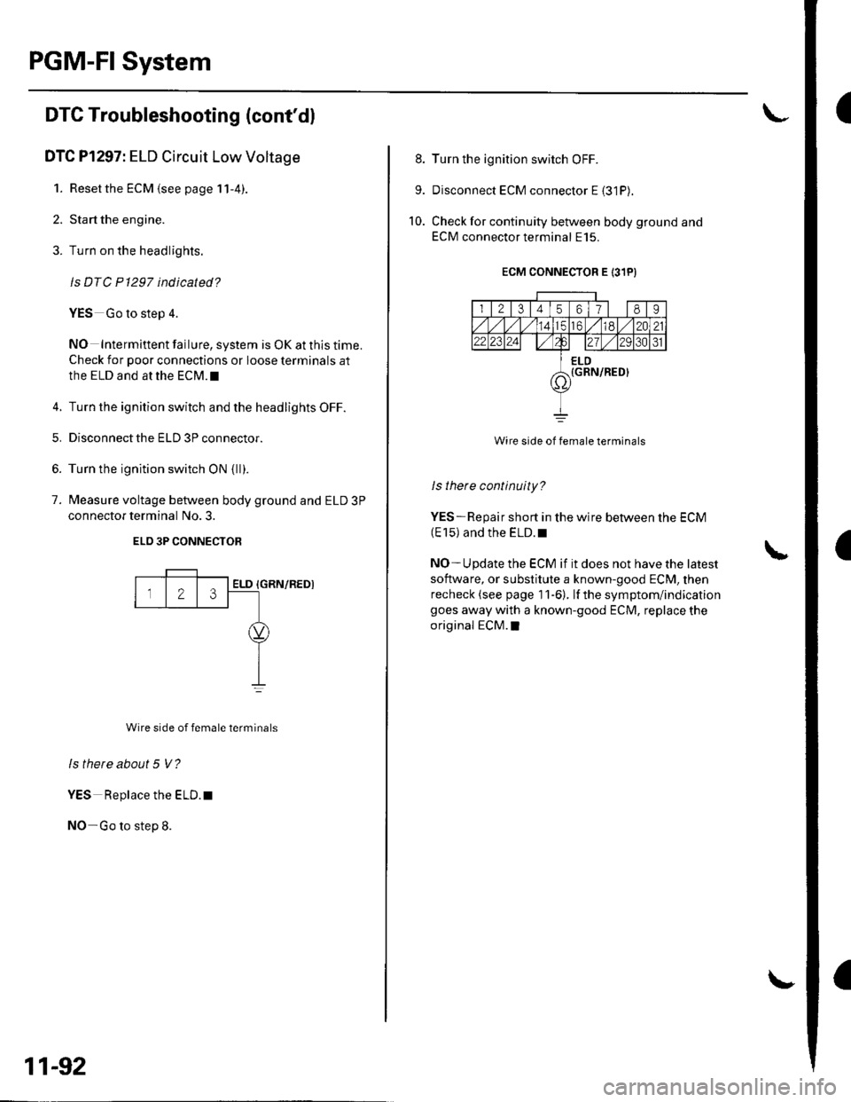
7. Measure voltage between body ground and ELD 3P
connector terminal No. 3.
ELO 3P CONNECTOB
{GRN/REDI
Wire side of female terminals
ls there about 5 V?
YES Replace the ELD. t
NO-Go to step 8.
Z3ELD
11-92
8. Turn the ignition switch OFF.
9. Disconnect ECM connector E {31P).
10. Check for continuity between body ground and
ECM connector terminal E15.
ECM CONNECTOR E 131PI
I l2l3456178I
totd/ 12021,2 2al2/tA31
ELD(GRN/RED}7\'
Wire side of female terminals
ls there continuity?
YES-Repair short in the wire between the ECM(E 15) and the ELD. r
NO- U pdate the ECM if it does not have the latest
software, or substitute a known-good ECM, then
recheck (see page 1 1-6). lf the symptom/indication
goes away with a known-good ECM, replace the
original ECM.I
Page 300 of 1139
DTC Pl298: ELD Circuit High Voltage
1. Resetthe ECM (see page 11-4)
2. Stan the engine.
3. Turn on the headlights.
ls DTC P1298 indicated?
YES-Go to step 4.
NO- Intermittent failure. system is OK at this time.
Check for poor connections or loose terminals at
the ELD and at the ECM.I
4. Turn the ignition switch and headlights OFF.
5. Disconnectthe ELD 3P connector.
6. Turn the ignition switch ON (ll).
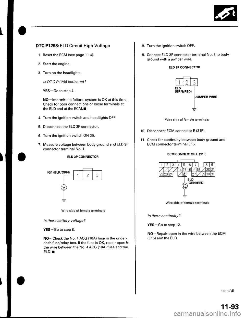
7. Measure voltage between body ground and ELD 3P
connector terminal No. 1.
ELD 3P CONNECTOR
IG1 IBLK/ORNI
Wire side ot {emale terminals
ls there battery voltage?
YES-Go to step 8.
NO-Checkthe No. 4 ACG (10A)fuse in the under-
dash fuse/relay box. lf the fuse is OK, repair open in
the wire between the No. 4 ACG (10A) fuse and the
ELD.I
8.
9.
10.
11.
Turn the ignition switch OFF.
Connect ELD 3P connector terminal No. 3 to body
ground with a jumper wire.
Disconnect ECM connector E (31P).
Check for continuity between body ground and
ECM connector terminal E15.
ECM CONNECTOR E 131PI
1 21345ot/II
14LC6l/ 182C21
22123 2421 ./2Q30J
ELDIGRN/RED)i1'
Wire side of female terminals
Is thete continuity?
YES-Go to step 12.
NO Repair open in the wire between the ECM
(E15) and the ELD.
(cont'd)
ELD 3P CONNECTOR
---F-------
l1l2 :rlELD(GRN/RED)
IJUMPER wrRE
II
Wire side of temale terminals
11-93
Page 301 of 1139
PGM-FI System
DTC Troubleshooting (cont'dl
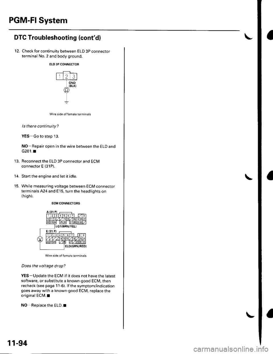
12, Check for continuity between ELD 3P connector
terminal No.2 and body ground.
ELD3P CONNECTOR
Wire side of female terminals
ls there continuity?
YES Go to step 13.
NO- Repair open in the wire between the ELD and
G201. I
Reconnect the ELD 3P connector and ECM
connector E (31P).
Start the engine and let it idle.
While measuring voltage between ECM connector
terminals 424 and E15, turn the headlights on
th igh).
ECM CONNECTORS
Wi.e side of female terminals
Does the voltage drop?
YES-Update the ECM if it does not have the latest
software, or substitute a known-good ECM, then
recheck {see page 1 1-6). lf the symptom/indicationgoes away with a known-good ECM, replace the
original ECM.I
NO Replace the ELD.I
14.
t5_
11-94
Page 302 of 1139
3.
4.
5.
6.
DTC Pl361: Camshaft Position (CMP) Sensor
B (TDC Sensor) Intermittent Interruption
DTC Pl362: Camshaft Position (CMP) Sensor
B (TDC Sensor) No Signal
1. Reset the ECM (see page 11-4).
2. Start the engine.
ls DTC P1361 and/or P1362 indicated?
YES Go to step 3.
NO- Intermittent failure. system is OK at this time.
Check for poor connections or loose terminals at
the CMP sensor B (TDC sensor) and at the ECM.I
Turn the ignition switch OFF.
Disconnectthe CMP sensor B (TDC sensor) 3P
connector.
Turn the ignition switch ON (ll).
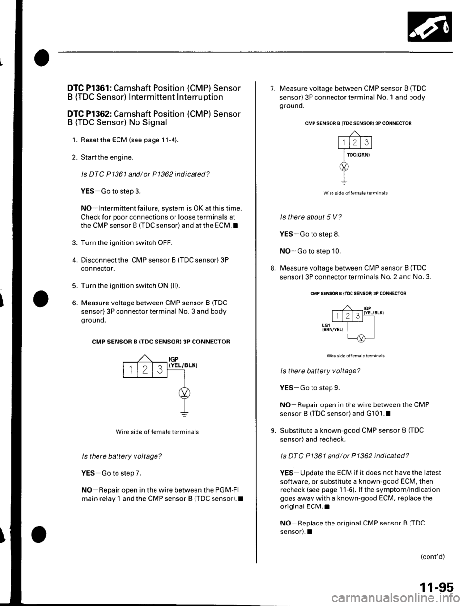
Measure voltage between CMP sensor B (TDC
sensor) 3P connector terminal No. 3 and body
grouno.
CMP SENSOR B {TDC SENSOR) 3P CONNECTOR
{YEL/BLK}
Wire side ol temale terminals
ls there battety voltage?
YES Go to step 7.
NO-Repair open in the wire between the PGM-Fl
main relay 1 and the CMP sensor I (TDC sensor).I
IGP
123
7. l\4easure voltage between CMP sensor B {TDC
sensor) 3P connector terminal No. 1 and body
ground.
CMP S€NSOR 8 ITDC SENSOR) 3P CONNECTOR
Wlre s de ollemaleterminals
ls there about 5 V?
YES-Go to step 8.
NO-Go to step 10.
8. Measure voltage between Cl\ilP sensor B (TDC
sensor) 3P connector terminals No. 2 and No, 3.
CMP SENSON B llOC SENSOfi) 3P CONNECTOF
Wire s de olfema etefminals
ls there battery voltage?
YES-Go to step 9.
NO Repair open in the wire between the CMP
sensor B (TDC sensor) and G101.1
9. Substitute a known-good CMP sensor B (TDC
sensor) and recheck.
ls DTC P1361 and/or P1362 indicated?
YES Update the ECM if it does not have the latest
software, or substitute a known-good ECM, then
recheck (see page 11-6). lf the symptom/indication
goes away with a known-good ECM, replace the
original ECM.I
NO Replace the original CMPsensorB(TDC
sensor).1
(cont'd)
11-95