relay HONDA CIVIC 2003 7.G Workshop Manual
[x] Cancel search | Manufacturer: HONDA, Model Year: 2003, Model line: CIVIC, Model: HONDA CIVIC 2003 7.GPages: 1139, PDF Size: 28.19 MB
Page 880 of 1139
Under-dash Fuse/Relay Box
Removal and Installation
SRS components are located in this area. Review the
SRS component locations {see page 23-13) andprecautions and procedures (see page 23-14) in the SRS
section before performing repairs or service.
Removal
1. Make sure you have the anti-theft code for the radio,
then write down the frequencies for the radio's
preset buttons.
2. Disconnectthe battery negative cable, then
disconnect the positive cable, and wait at least
three minutes.
3. Remove the driver's dashboard lower cover (see
page 20-59).
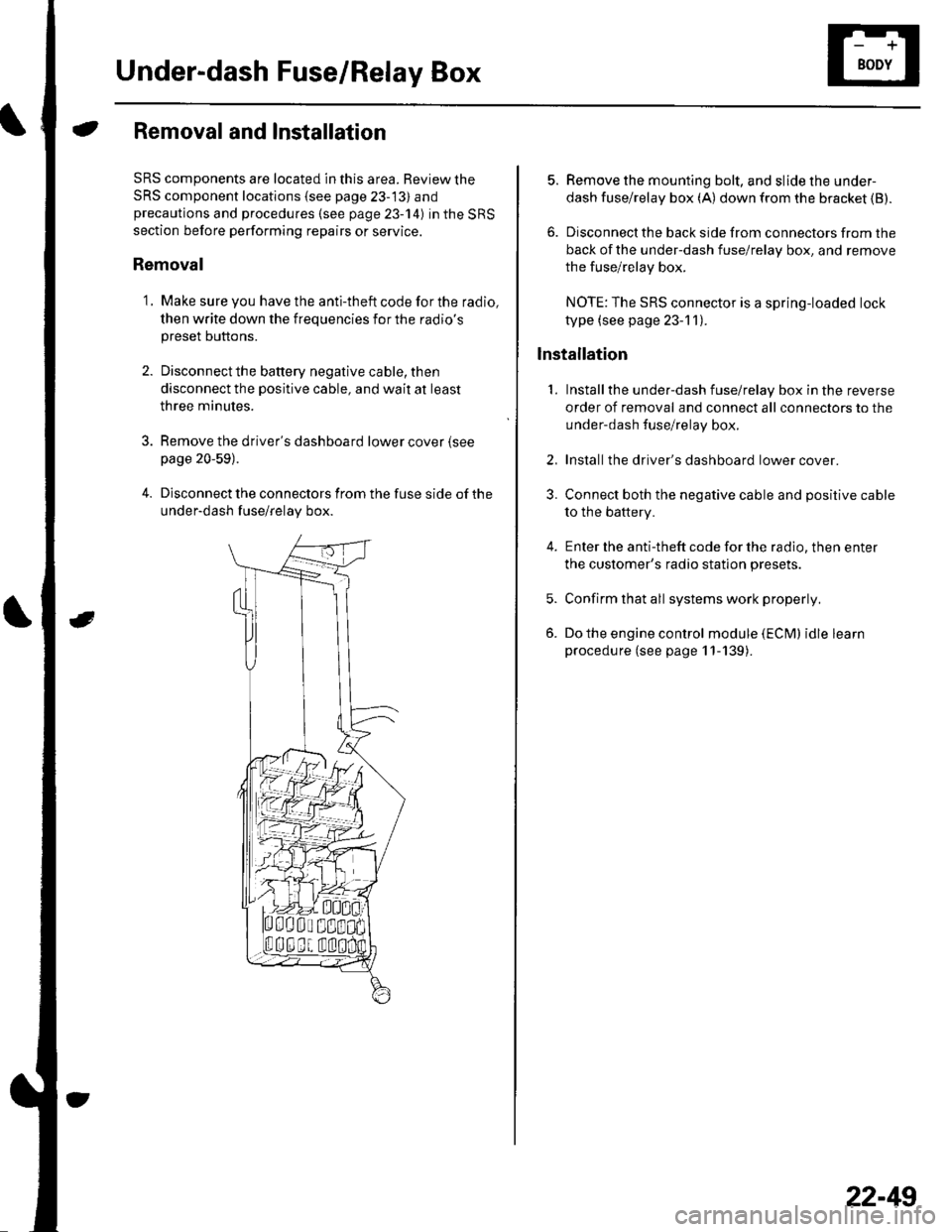
4. Disconnect the connectors from the fuse side of the
under-dash fuse/relay box.
5. Remove the mounting bolt, and slide the under-
dash fuse/relay box (A) down from the bracket {B).
6. Disconnect the back side from connectors from the
back of the under-dash fuse/relay box, and remove
the fuse/relay box.
NOTE:The SRS connector is a spring-loaded lock
type (see page 23-1 1).
lnstallation
1. Installthe under-dash fuse/relay box in the reverse
order of removal and connect all connectors to the
under-dash fuse/relay box.
2. Installthe driver's dashboard lower cover.
3. Connect both the negative cable and positive cable
to the battery.
4. Enter the anti-theft code for the radio, then enter
the customer's radio station presets.
5. Confirm that all systems work properly,
6. Do the engine control module (ECM) idle learn
procedure (see page 11-139).
22-49
Page 882 of 1139
Relays
Power Relay Test
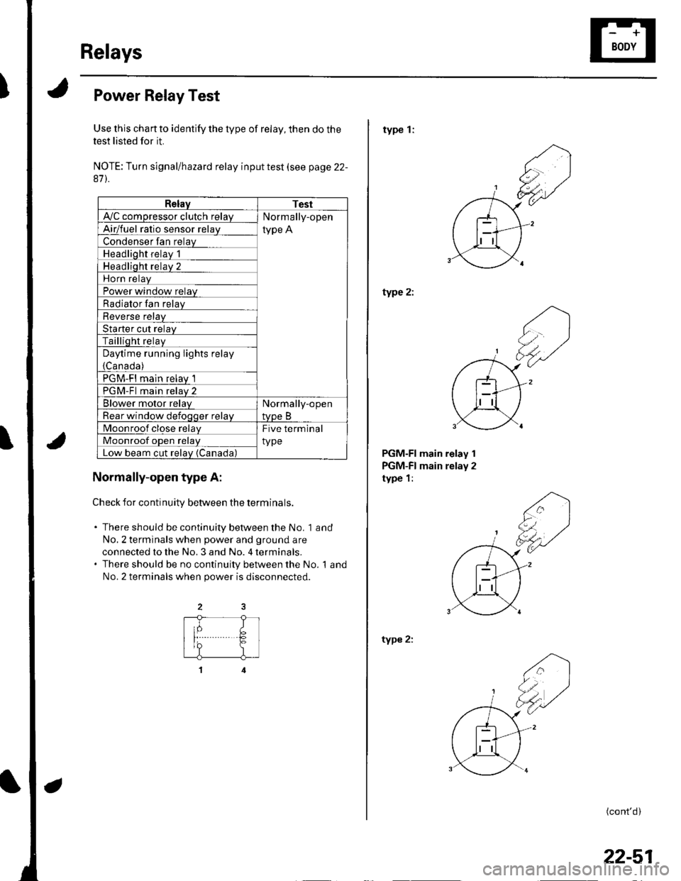
Use this chan to identify the type of relay, then do the
test listed for it.
NOTE: Turn signal/hazard relay input test (see page 22-
87).
RelayTest
A'lC comoressor clutch relavNormally-open
type AAirlfuel ratio sensor relav
Condenser fan relay
Headlioht relav 1
Headliqht relav 2
Horn relav
Power window relay
Radiator Ian relay
Reverse relav
Starter cut relav
Tailliqht relaV
Daytime running lights relay
{Canada )
PGM-FI main relav 1
PGM-Fl main relav 2
Blower motor relavNormally-open
tvpe BRear window defoqoer relav
Moonroof close relayFive terminal
typeMoonroof oDen relav
Low beam cut relav {Canada)
Normally-open type A:
Check for continuitv between the terminals.
. There should be continuity between the No. 1 and
No,2 terminals when power and ground are
connected to the No. 3 and No. 4 terminals.. There should be no continuity between the No. 1 and
No.2 terminals when power is disconnected.
type 1:
type 2:
PGM-FI main relay 1
PGM-FI main relay 2
type 1:
type 2:
(cont'd)
22-51
Page 883 of 1139
Relays
Power Relay Test (confdl
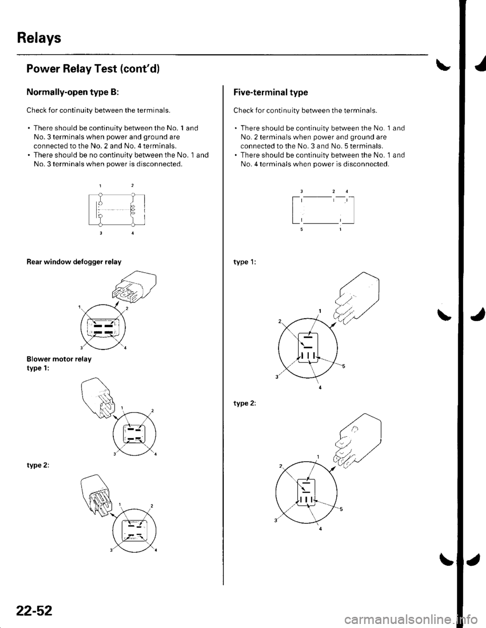
Normally-open type B:
Check for continuity between the terminals.
. There should be continuity between the No. 1 and
No. 3 terminals when power and ground are
connected to the No. 2 and No. 4 terminals.' There should be no continuity between the No, 'l and
No. 3 terminals when power is disconnected.
Blower motor relay
type 1:
type 2;
tF-gr
tJ 1l
Rear window defonn* *O,
6:)
rc*V
.r{{
n,\
(Ft)
s3.
22-52
Five-terminal type
Check for continuity between the terminals.
. There should be continuity between the No. 1 and
No.2 terminals when power and ground are
connected to the No. 3 and No. 5 terminals.. There should be continuity between the No. 1 and
No. 4 terminals when power is disconnected.
type 1:
type 2:
\
Page 884 of 1139
lgnition Switch
Test
SRS components are located in this area. Review the
SRS component locations (see page 23-13) andprecautions and procedures {see page 23-'l4) in the SRS
section before performing repairs or service.
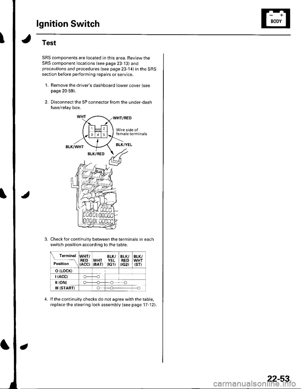
1, Remove the driver's dashboard lower cover {seepage 20-59).
2. Disconnect the 5P connector from the under-dash
fuse/relay box.
WHT/RED
Wire side offemale terminals
BLK/WHTBLK/YEL
BLK/RED
Check for continuity between the terminals in each
switch position according to the table.
Terminal
p.J,i""-\
WHT/RED(ACC)
BLK/WHT YEL(BAT) flGl)
BLK/REDtrc2t
BLK/WHT(sr)
o (LocK)
| (ACC)o---o
[ (oN)
III (START)
c)-_H
o_H
lf the continuity checks do not agree with the table,
replace the steering lock assembly (see page'17-121.
22-53
Page 887 of 1139
Gauges
Self-diagnostic Procedure
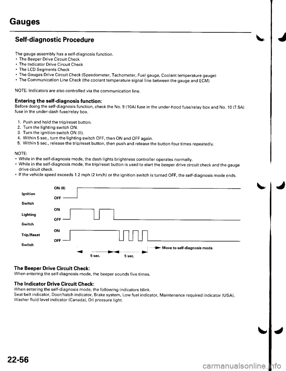
The gauge assembly has a self-diagnosis function.. The Beeper Drive Circuit Check. The Indicator Drive Circuit ChecL. The LCD Segments Check. The Gauges Drive Circuit Check (Speedometer, Tachometer, Fuel gauge, Coolant temperature gauge). The Communication Line Check (the coolanttemperature signal line between the gauge and ECM)
NOTE: Indicators are also controlled via the communication line.
Entering the self-diagnosis f unction:
Before doing the self-diagnosis function, check the No. 9 (10A) fuse in the under-hood fuse/relay box and No. 10 {7.5A)fuse in the under'dash fuse/relay box.
1. Push and hold the trip/reset button.
2. Turn the lighting switch ON.
3. Turn the ignition switch ON (ll).
4. Within 5 sec., turn the lighting switch OFF, then ON and OFF again.5. Within 5 sec., release the trip/reset button, then push and release the button four times reDeatedlv.
NOTE:. While in the self-diagnosis mode, the dash lights brightness controller operates normally.'Whileintheself-diagnosismode,thetrip/resetbuttonisusedtostartthebeeperdrivecircuitcheckandthegauge
drive cicuit check.. lf the vehicle speed exceeds 1.2 mph 12 km/h) orthe ignition switch is tu rned OFF, the self,diag nosis mode ends.
oN flrl
lgnition
Switch
Lighting
Switch
Trip/Reset
Switch-> Move to selt-diagnosis mode.
5 sec.5 sec.
The Beeper Drive Circuit Check:
When entering the self-diagnosis mode, the beeper sounds five times
The Indicator Drive Circuit Check:
When entering the self-diagnosis mode, the following indicators blink.
Seat belt indicator, Door/hatch indicator, Brake system, Lowfuel indicator, Maintenance required indicator (USA),
Washer fluid level indicator (Canada), Oil pressure light.
v
OFF
22-56
Page 895 of 1139
Gauges
2.
3.
Gauge Assembly Replacement
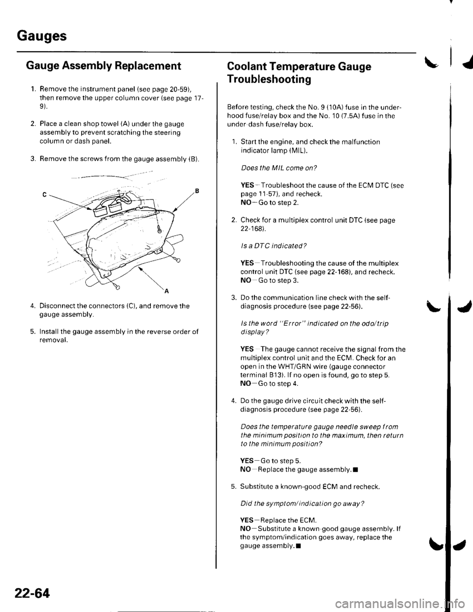
1.Remove the instrument panel (see page 20-59),
then remove the upper column cover {see page 17-
Place a clean shop towel (A) under the gauge
assembly to prevent scratching the steering
colum n or dash panel.
Remove the screws from the gauge assembly (B).
Disconnect the connectors (C), and remove thegauge assemDry.
Installthe gauge assembly in the reverse order of
removal.
Coolant Temperature Gauge
Troubleshooting
Before testing, check the No. I { 10A) fuse in the under-
hood fuse/relay box and the No. '10 (7.5A) fuse in the
under dash fuse/relay box.
1. Start the engine, and check the malfunction
indicator lamp (MlL).
Does the MIL come on?
YES- Troubleshoot the cause of the ECM DTC (see
page 1 1-57), and recheck.
NO-Go to step 2.
2. Check for a multiplex control unit DTC (see page
22,168).
ls a DTC ind icated?
YES Troubleshooting the cause of the multiplex
control unit DTC {see page 22-168), and recheck.
NO Go to step 3.
3. Do the communication line check with the self-
diagnosis procedure (see page 22-56).
ls the word "Error" indicated on the odo/ttip
d isplay ?
YES The gauge cannot receive the signal from the
multiplex control unit and the ECI\,4. Check for an
open in the WHT/GRN wire (gauge connector
terminal B 13). lf no open is found, go to step 5.
NO Go to step 4.
4. Do the gauge drive circuit check with the self-
diagnosis procedure (see page 22-56).
Does the temperature gauge needle sweep lrom
the minimum position to the maximum, then tetutn
to the minimum position?
YES Go to step 5.
NO Replace the gauge assembly.l
5. Substitute a known-good ECM and recheck.
Did the symptom/ ind ication go away?
YES Replace the ECM.
NO Substitute a known good gauge assembly. lf
the symptom/indication goes away, replace thegauge assembly.l
4.
22-64
Page 896 of 1139
IVehicle Speed Signal Circuit Troubleshooting
Special Tools Required:
Test Harness 07LAJ-PT3020A
Before testing, inspect the No. 4 (10A) and No. 10 (7.5A)
fuses in the under-dash fuse/relay box.
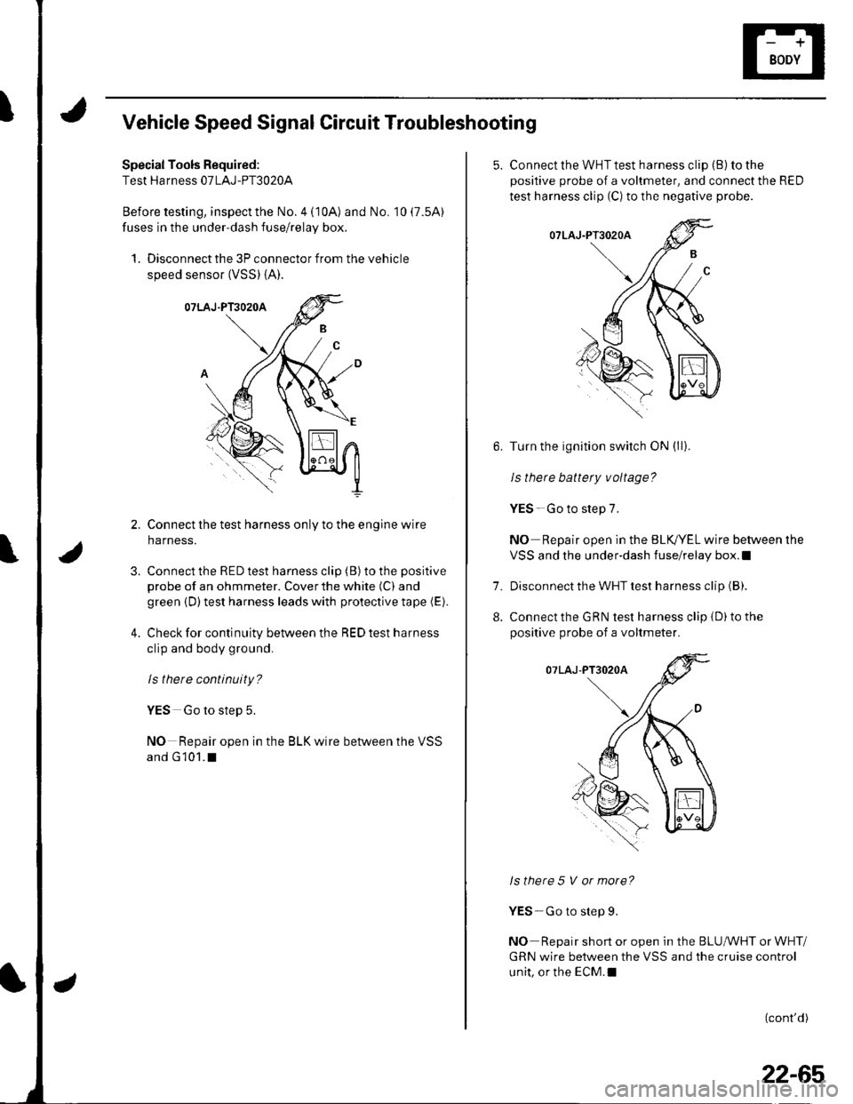
1. Disconnect the 3P connector from the vehicle
speed sensor (VSS) {A).
Connect the test harness only to the engine wire
harness.
Connect the RED test harness clip (B) to the positive
probe of an ohmmeter. Cover the white (C) and
green {D) test harness leads with protective tape (E).
Check for continuity between the RED test harness
clip and body ground,
ls there continuity?
YES Go to step 5.
NO Repair open in the BLK wire between the VSS
and G 101.I
3.
4.
5. Connect the WHT test harness cliD (B) to the
positive probe of a voltmeter, and connect the RED
test harness clip (C) to the negative probe.
Turn the ignition switch ON (ll).
le thara h2ltarv v^ltada?
YES-Go to step 7.
NO Repair open in the BLK,/YEL wire between the
VSS and the under-dash fuse/relay box.l
Disconnect the WHT test harness clip (B).
Connect the GRN test harness clip {D) to the
positive probe of a voltmeter.
Is there 5 V or more?
YES- Go to step 9.
NO Repair short or open in the BLUMHT or WHT/
GRN wire between the VSS and the cruise control
unit, or the ECM.I
(cont'd)
7.
8.
22-65
Page 899 of 1139
Exterior Lights
Gomponent Location Index
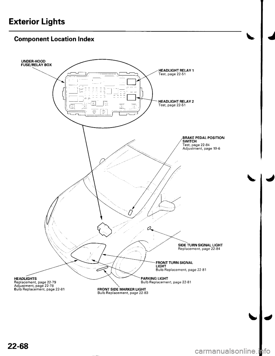
UNDER.HOODFUSE/RELAY BOX
\/
HEADLIGHTSReplacement, page 22 79Adjustment. page 22-78Eulb Replacement, page 22-81
HEADLIGHT RELAY 1Test, page 22-51
HEADLIGHT RELAY 2Test, page 22-5'l
0/
FRONT SIDE MARKER LIGHTBulb Replacement, page 22 83
BRAKE PEDAL POSITIONswtTcHTest, page 22-84Adjustment, page l9'6
SIDE TURN SIGNAL LIGHTReplacement, page 22-84
FRONT TURN SIGNALLIGHTBulb Beplacement, page 22 81
PARKING LIGHTBulb Replacement, page 22-81
22-68
Page 901 of 1139
Exterior Lights
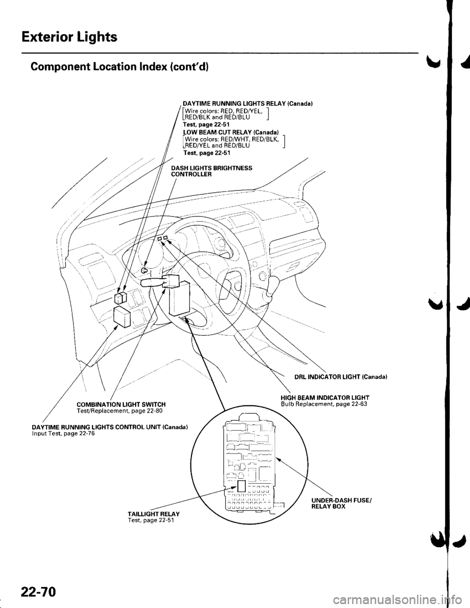
Component Location Index (cont'dl!
DAYTIME RUNNING LIGHTS RELAY {Canadal[Wire colors: RED, REDryEL, ILRED/BLK and RED/BLU ITest, page 22-51
_LOW BEAM CUTRELAY {Canadal _Wire colorsr REDMHT, RED/BLK, ILREDryEL and RED/BLU ITest, page 22-51
DASH LIGHTS BRIGHTNESSCONTROLLER
/
COMBINATION LIGHT SWITCHTesVReplacement, page 22-80
oAYTIME RUNNING LIGHTS CONTROL UNIT lcanada)Input Test, page 22-76
DRL INDICATOR LIGHT {Canadal
HIGH BEAM INDICATOR LIGHTBulb Replacement, page 22-63
UNDER.DASH FUSE/RELAY BOX
:' --,': - '
' i,-'-'l
..i \
I t- -
22-70
Page 908 of 1139
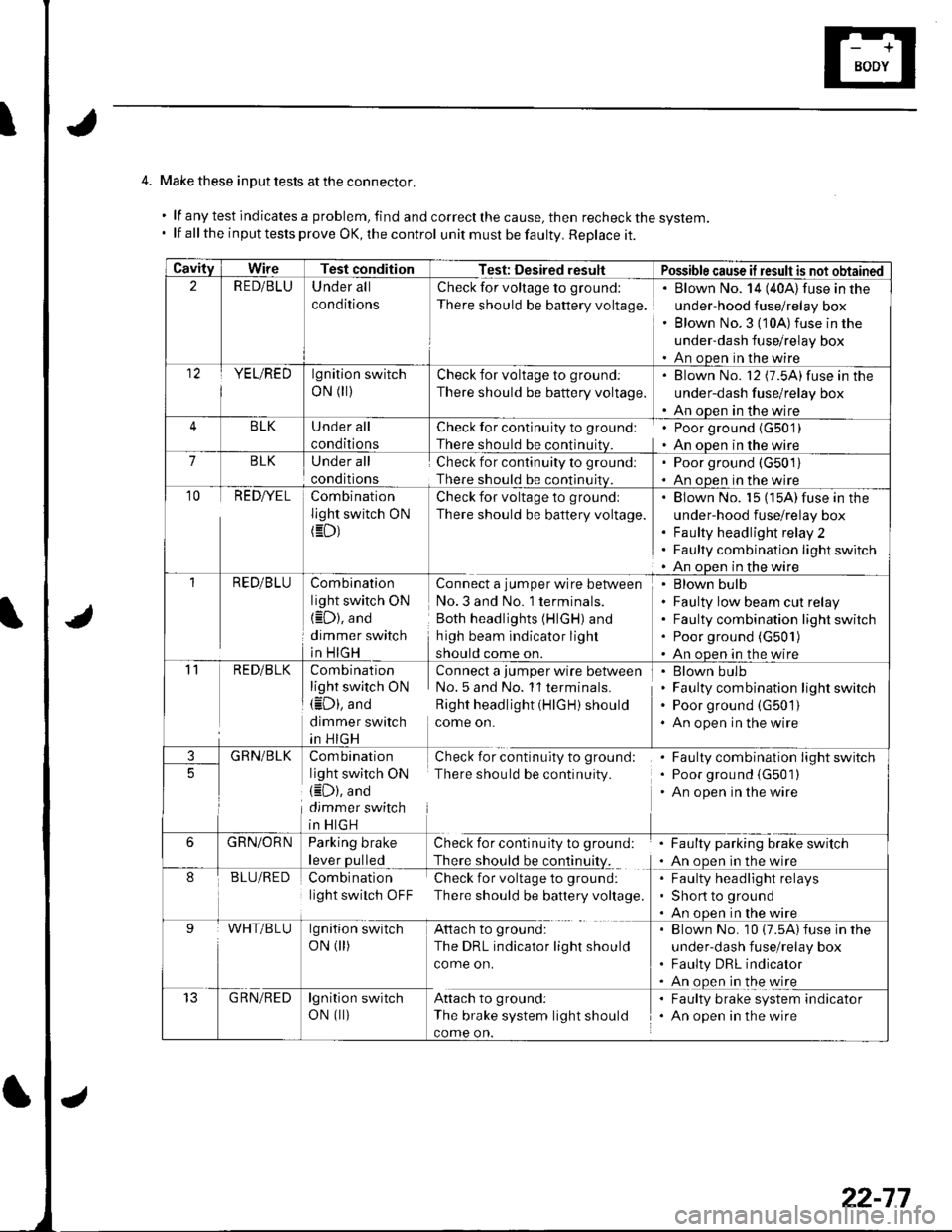
4. Make these input tests at the connector,
.lfanytestindicatesaproblem,findandcorrectthecause,thenrecheckthesystem.
. lf all the input tests prove OK, the control unit must be faulty. Replace it.
CavityWireTest conditionTest: Desired resultPossible cause if result is not obtained2R E D/BLUUnder all
conditions
Check for voltage to ground:
There should be battery voltage.
Blown No. 14 (40A) fuse in the
under-hood fuse/relay box
Blown No. 3 {10A)fuse in the
under-dash fuse/relay box
An open in the wire12YE L/RE Dlgnition switch
oN (r)Check for voltage to ground:
There should be battery voltage.
Blown No. l2 (7.5A)fuse in the
under-dash fuse/relay box
An open in the wire
BLKUnder all
conditions
Check for continuity to ground:
There should be continuitv.
. Poor ground {G50'1). An oDen in the wire7BLKUnder all
conditions
Check for continuity to ground:
There should be continuitv.
. Poor ground (G501)
' An open in the wire
10REDI/ELCombination
light switch ON/ =f\
Check for voltage to ground:
There should be battery voltage.
Blown No. 15 (15A) fuse in the
under-hood fuse/relay box
Faulty headlight relay 2
Faulty combination light switch
An open in the wire
1RED/B LUCombination
light switch ON
{iD), and
dimmer switch
in HIGH
Connect a jumper wire between
No.3 and No. 1 terminals.
Both headlights (HIGH) and
h igh beam indicator light
should come on.
Blown bulb
Faulty low beam cut relay
Faulty combination light switch
Poor ground (G50'l )
An open in the wire'11
3
RED/BLK
GRN/BLK
Combination
light switch ON(iD), and
dimmer switch
in HIGH
Com bination
light switch ON(iD), and
dimmer switch
in HIGH
Connect a jumper wire between
No. 5 and No. 11 terminals.
Right headlight (HIGH) should
come on.
Check for continulty to ground
There should be continuity.
. Blown bulb. Faulty combination light switch. Poor ground (G 50'1 ). An open in the wire
. Faulty combination light switch. Poor grou nd {G501). An open in the wire
5
6GRN/ORNParking brake
lever oulled
Check for continuity to ground:
There should be continuitv.
Faulty parking brake switch
An open in the wire
8BLU/REDCombination
light switch OFF
Check for voltage to ground:
There should be battery voltage.
Faulty headlight relays
Short to ground
An ooen in the wire
WHT/BLUlgnition switch
oN 0r)
Attach to ground:
The DRL indicator light should
come on.
. Blown No. 10 (7.5A) fuse in the
under-dash fuse/relay box. Faulty DRL indicator. An ooen in the wire
t5G RN/REDlgnition switch
oN (||)Attach to ground:
The brake system light should
come on.
Faulty brake system indicator
An open in the wire
22-77