relay HONDA CIVIC 2003 7.G Manual Online
[x] Cancel search | Manufacturer: HONDA, Model Year: 2003, Model line: CIVIC, Model: HONDA CIVIC 2003 7.GPages: 1139, PDF Size: 28.19 MB
Page 801 of 1139
Heating and Air Conditioning
Radiator and Condenser Fans
Common
(cont'dl
Circuit Troubleshooting
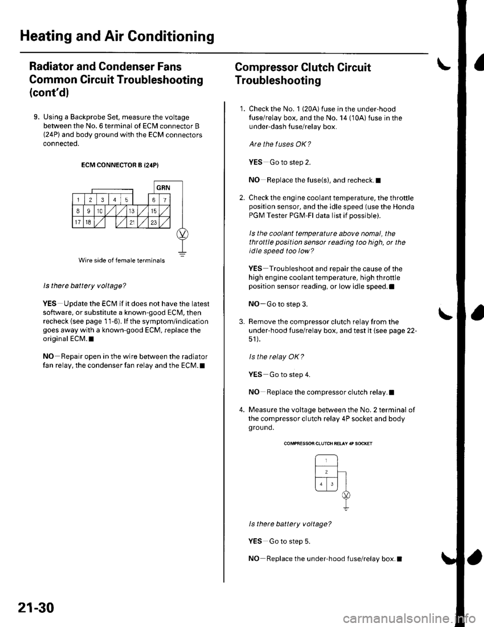
9. Using a Backprobe Set, measure the voltage
between the No. 6 terminal of ECN4 connector B
{24P) and body ground with the ECM connectors
connecteo.
ECM CONNECTOR B {24P}
ls there battery voltage?
YES UDdate the ECM if it does not have the latest
so{tware, or substitute a known-good ECM, then
recheck (see page 11-6). lf the symptom/indication
goes away with a known-good ECM, replace the
original ECM.I
NO Repair open in the wire between the radiator
fan relay, the condenser fan relay and the ECM. t
Wire side of female terminals
21-30
Compressor Clutch Circuit
Troubleshooting
1. Check the No. 1 (20A) fuse in the under-hood
fuse/relay box, and the No. 14 {10A)fuse in the
under-dash fuse/relay box.
Are the tuses OK?
YES Go to step 2.
NO Replace the fuse(s), and recheck.I
2. Check the engine coolant temperature, the throttleposition sensor, and the idle speed (use the Honda
PGM Tester PGM-Fl data list if possible).
ls the coolant temperaturc above nomal, the
throttle position sensor rcading too high, or the
idle speed too low?
YES Troubleshoot and repair the cause of the
high engine coolant temperature, high throttle
position sensor reading, or low idle speed.l
NO-Go to step 3.
3. Remove the compressor clutch relay from the
under-hood fuse/relay box, and test it (see page 22-
51 ).
ls the relay OK?
YES Go to step 4.
NO Replace the compressor clutch relay.I
4. Measure the voltage between the No. 2 terminal of
the compressor clutch relay 4P socket and body
ground.
\
COMPfiESSON CLUTCH BELAY 'P SOCKET
ls there battery voltage?
YES Go to step 5.
NO Replace the under-hood fuse/relay box.I
Page 802 of 1139
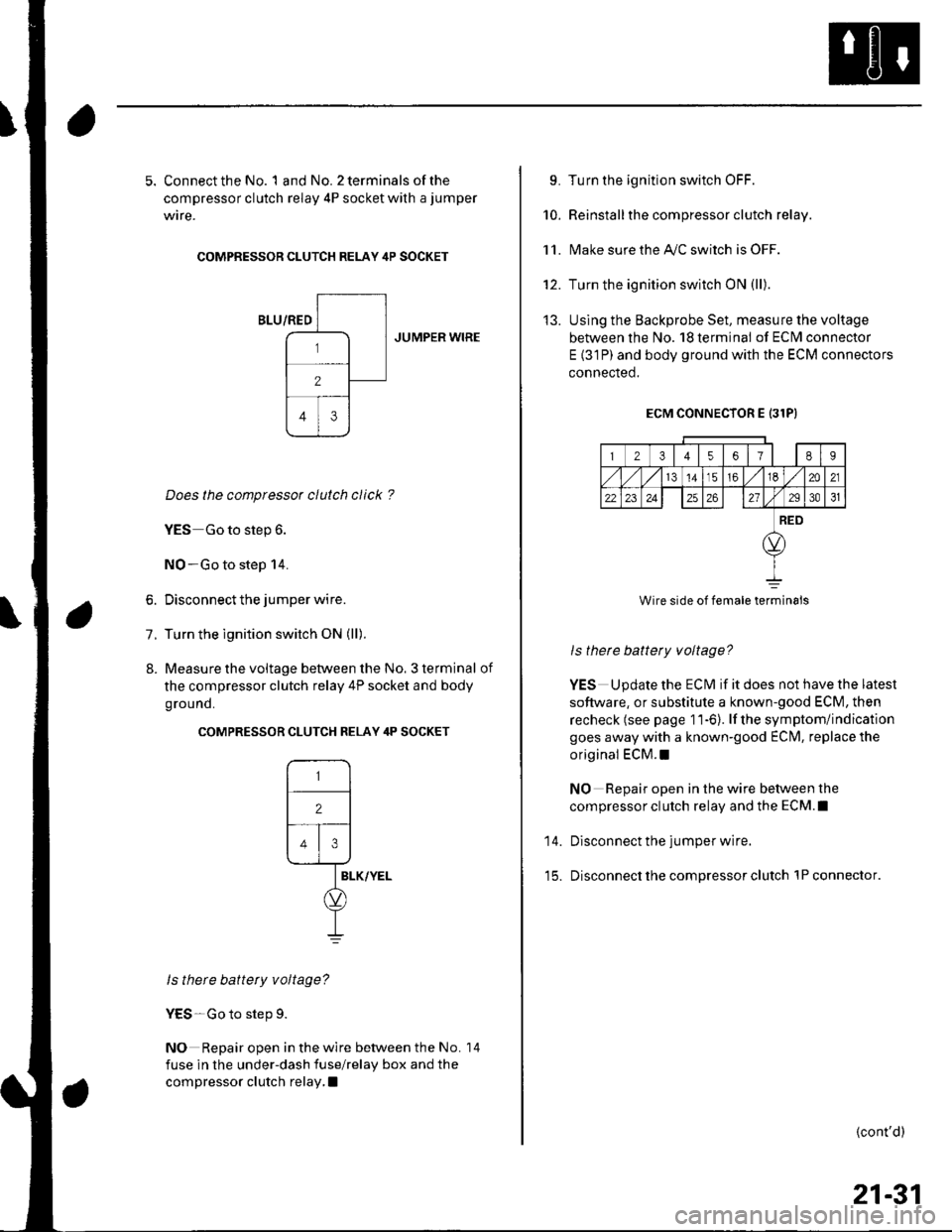
5. Connect the No. 1 and No. 2 terminals of the
compressor clutch relay 4P socket with a jumper
wire.
COMPRESSOR CLUTCH RELAY 4P SOCKET
JUMPER WIRE
Does the compressor clutch click ?
YES Go to step 6.
NO-Go to step 14.
6. Disconnect the jumper wire.
7. Turn the ignition switch ON (ll).
8. Measure the voltage between the No. 3 terminal of
the compressor clutch relay 4P socket and body
ground.
COMPRESSOR CLUTCH RELAY 4P SOCKET
ls there battery voltage?
YES-Go to step 9.
NO Repair open in the wire between the No.
fuse in the under-dash fuse/relay box and the
compressor clutch relay, I
14
L Turn the ignition switch OFF.
10. Reinstallthe compressor clutch relay.
1 1. l\4ake sure the Ay'C switch is OFF.
12. Turn the ignition switch ON {ll).
13. Uslng the Backprobe Set, measure the voltage
between the No. 18 termina! of ECI\4 connector
E {31P) and body ground with the ECM connectors
connected.
ECM CONNECTOR E 131P}
23t4561E9
141516m21
22232426272931
RED
Wire side of female terminals
ls there battery voltage?
YES Update the ECM if it does not have the latest
software, or substitute a known-good ECM, then
recheck (see page 11-6). lf the symptom/indication
goes away with a known-good ECIM, replace the
original ECM.I
NO Repair open in the wire between the
compressor clutch relay and the ECM.I
14. Disconnect the jumper wire.
15. Disconnect the compressor clutch lPconnector.
{cont'd)
21-31
Page 803 of 1139
Heating and Air Conditioning
Compressor Clutch Circuit
Troubleshooting (cont'dl
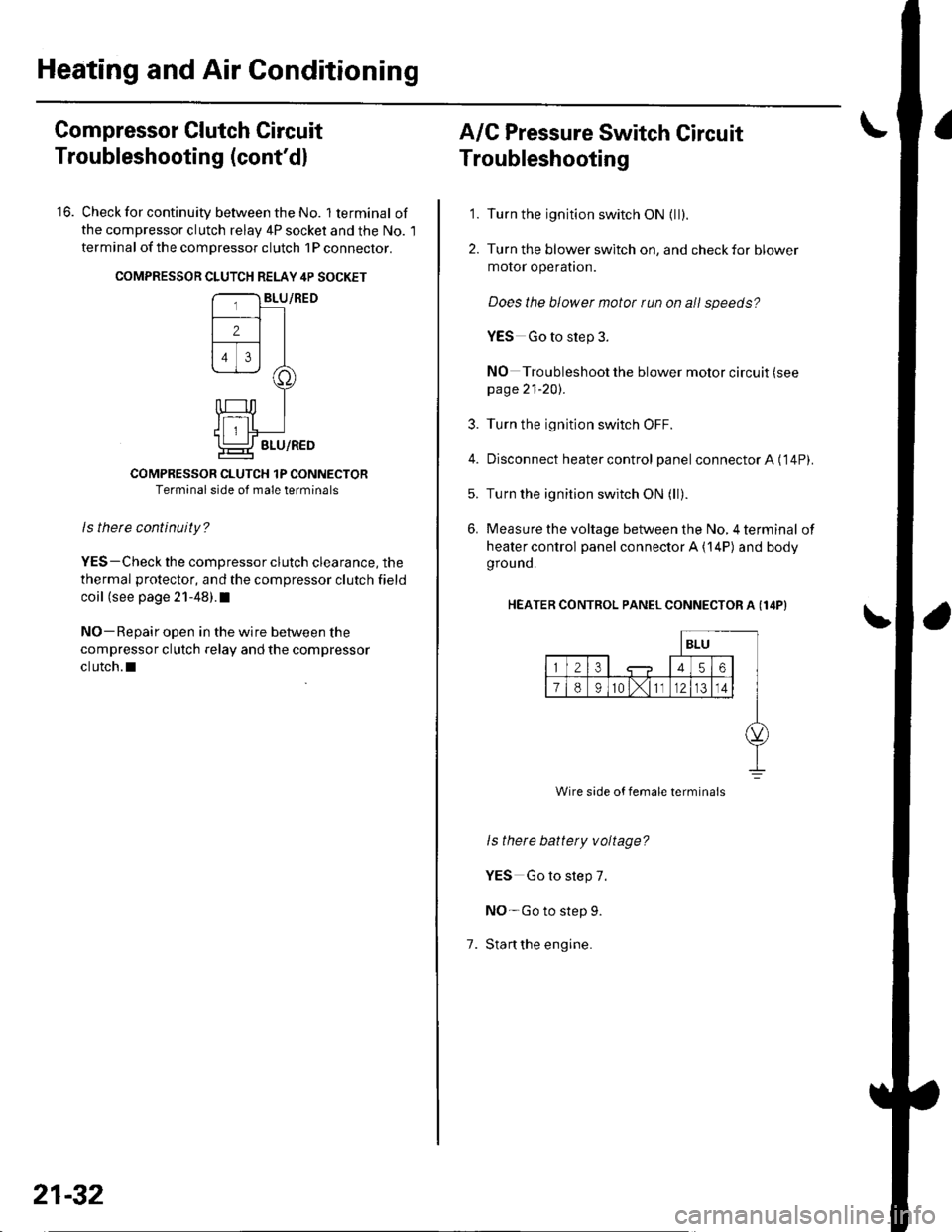
16. Check for continuity between the No. lterminal of
the compressor clutch relav 4P socket and the No. l
terminal of the compressor clutch 1P conneclor.
COMPRESSON CLUTCH RELAY 4P SOCKET
COMPRESSOR CLUTCH 1P CONNECTORTerminal side of male terminals
ls therc continuity?
YES-Check the compressor clutch clearance, the
thermal protector, and the compressor clutch field
coil (see page 21-48).I
NO-Repair open in the wire between the
compressor clutch relay and the compressor
clutch.l
21-32
A/C Pressure Switch Circuit
Troubleshooting
'1. Turn the ignition switch ON {ll).
2. Turn the blower switch on, and check for blower
motor operatron.
Does the blower motor run on all speeds?
YES Go to step 3.
NO Troubleshoot the blower motor circuit (see
page 21-20).
3. Turn the ignition switch OFF.
4. Disconnect heater control panel connectorA ('14P).
5. Turn the ignition switch ON (ll).
6. Measure the voltage between the No, 4 terminal of
heater control panel connector A {14P) and body
grou nd.
HEATER CONTROL PANEL CONNECTOR A (I4P}
1.
ls there battety voltage?
YES Go to step 7.
NO-Go to step 9.
Stan the engine.
Wire side of female termina's
Page 804 of 1139
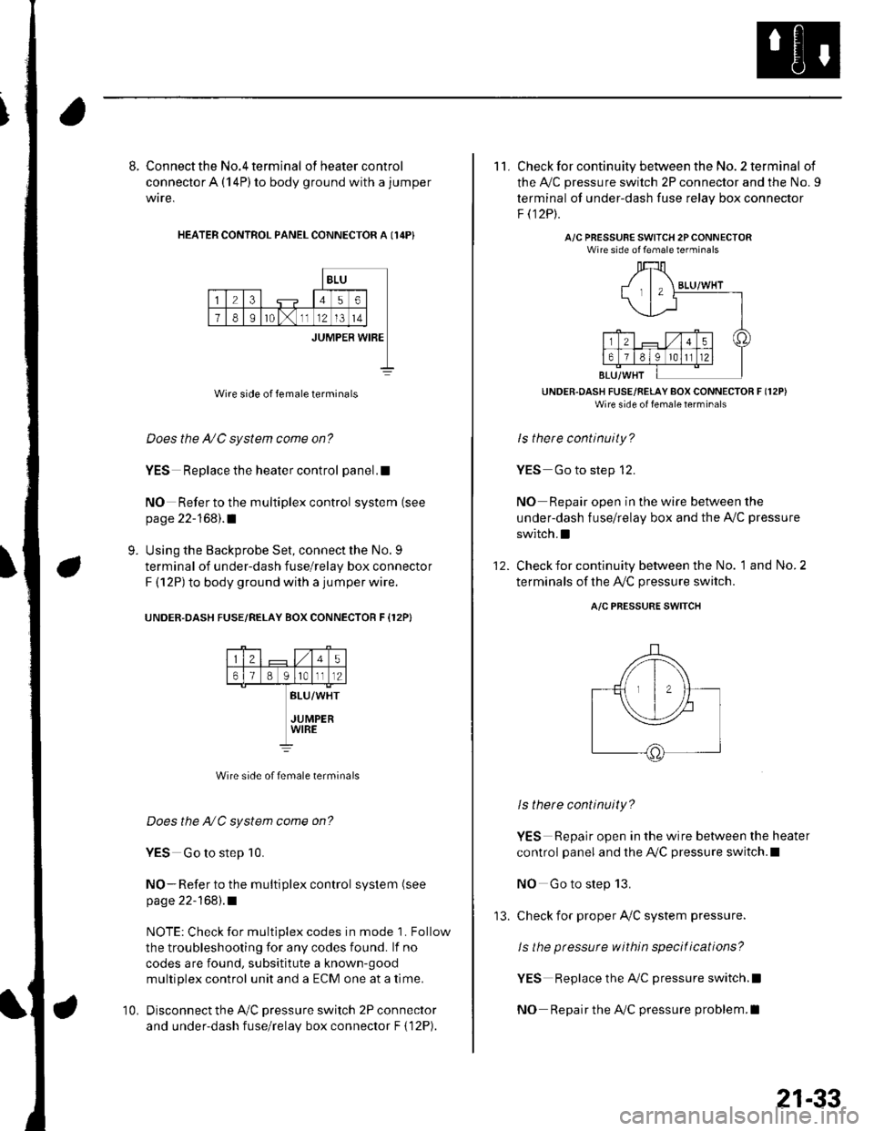
8. Connect the No.4 terminal ofheatercontrol
connector A (14P) to body ground with a jumper
wire,
HEATER CONTROL PANEL CONNECTOR A I14P}
BLU
23456
78Ir0lx1112l3t4
JUMPER WIBE
Wire side of female terminals
Does the A/C system come on?
YES Replace the heater control panel.!
NO Refer to the multiplex control system (see
page 22-168).1
Using the Backprobe Set, connect the No. 9
terminal of under-dash fuse/relay box connector
F (12P) to body ground with a jumper wire.
UNOER.DASH FUSE/RELAY BOX CONNECTOR F {12P}
9.
25
61B g lrotll2
BLU/WHT
JUMPERWIRE
Wire side of female terminals
Does the NC system come on?
YES Go to step 10.
NO- Refer to the multiplex control system (see
page 22-168).1
NOTE: Check for multiplex codes in mode '1. Follow
the troubleshooting {or any codes found. lf no
codes are found, subsititute a known-9ood
multiplex control unit and a ECM one at a time.
Disconnect the Ay'C pressure switch 2P connector
and under-dash fuse/relay box connector F { 12P).
10.
'13.
21-33
11. Check for continuity between the No. 2 terminal of
the A,/C pressure switch 2P connector and the No. 9
terminal of under-dash fuse relav box connector
F t12Pt.
A/C PRESSURE SWITCH 2PCONNECTORWire side of female terminals
UNDER.OASH FUSE/RELAY BOX CONNECTOR F (12P)
Wire side of fenale lerrrinal'
ls there continuity?
YES Go to step 12.
NO Repair open in the wire between the
under-dash fuse/relay box and the A,,/C pressure
switch.I
Check for continuity between the No. 1 and No. 2
terminals of the A,/C pressure switch.
12.
A/C PRESSURE SWITCH
ls there continuity?
YES Repair open in the wire between the heater
control panel and the A,/C pressure switch.l
NO Go to step 13.
check for proper Ay'C system pressure.
ls the pressure within specitications?
YES Replace the AilC pressure switch.l
NO Repair the AilC pressure problem.I
Page 805 of 1139
Heating and Air Conditioning
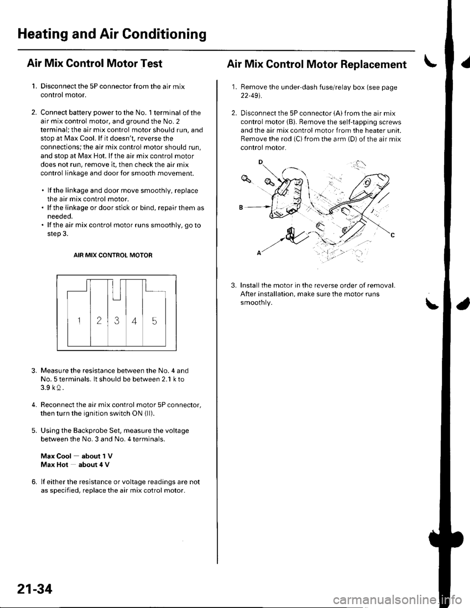
Air Mix Control Motor Test
1. Disconnect the 5P connector from the air mix
control motor.
2. Connect battery powertothe No. l terminal ofthe
air mix control motor, and ground the No. 2
terminal; the air mix control motor should run, and
stop at Max Cool. lf it doesn't, reverse the
connections;the air mix control motor should run,
and stop at Max Hot. lf the air mix control motor
does not run, remove it. then check the air mix
control linkage and door for smooth movement.
. lf the linkage and door move smoothly, replace
the air mix control motor.. lf the linkage ordoorstickor bind, repairthem as
needed.. lf the air mix control motor runs smoothly, go to
step 3.
AIR MIX CONTROL MOTOR
3.
4.
Measure the resistance between the No. 4 and
No. 5 terminals. lt should be between 2.1 k to
3.9 kQ.
Reconnect the air mix control motor 5P connector,
then turn the ignition switch ON {ll).
Using the Backprobe Set, measure the voltage
between the No. 3 and No. 4 terminals.
Max Cool about 1V
Max Hot about 4 V
lf either the resistance or voltage readings are not
as specified, replace the air mix cotrol motor.
21-34
Air Mix Control Motor Replacement
1.Remove the under-dash fuse/relay box (see page
22-491.
Disconnect the 5P connector {A) from the air mix
control motor (B). Remove the self-tapping screws
and the air mix control motor from the heater unit.
Remove the rod (C) from the arm (D) of the air mix
controi motor.
Install the motor in the reverse order of removal.
After installation, make sure the motor runs
smoothly.
3.
\'
,.,:l'
Page 806 of 1139
Mode Control Motor Test
Disconnect the 10P connector from the mode
control motor.
Connect battery power to the No. 1 terminal of the
mode control motor, and ground the No. 2
terminal; the mode control motor should run
smoothly and stop at Defrost. lf it doesn't, reverse
the connections; the mode control motor should
run smoothly and stop at Vent. When the mode
control motor stops running, disconnect battery
power immediately.
'1.
4.
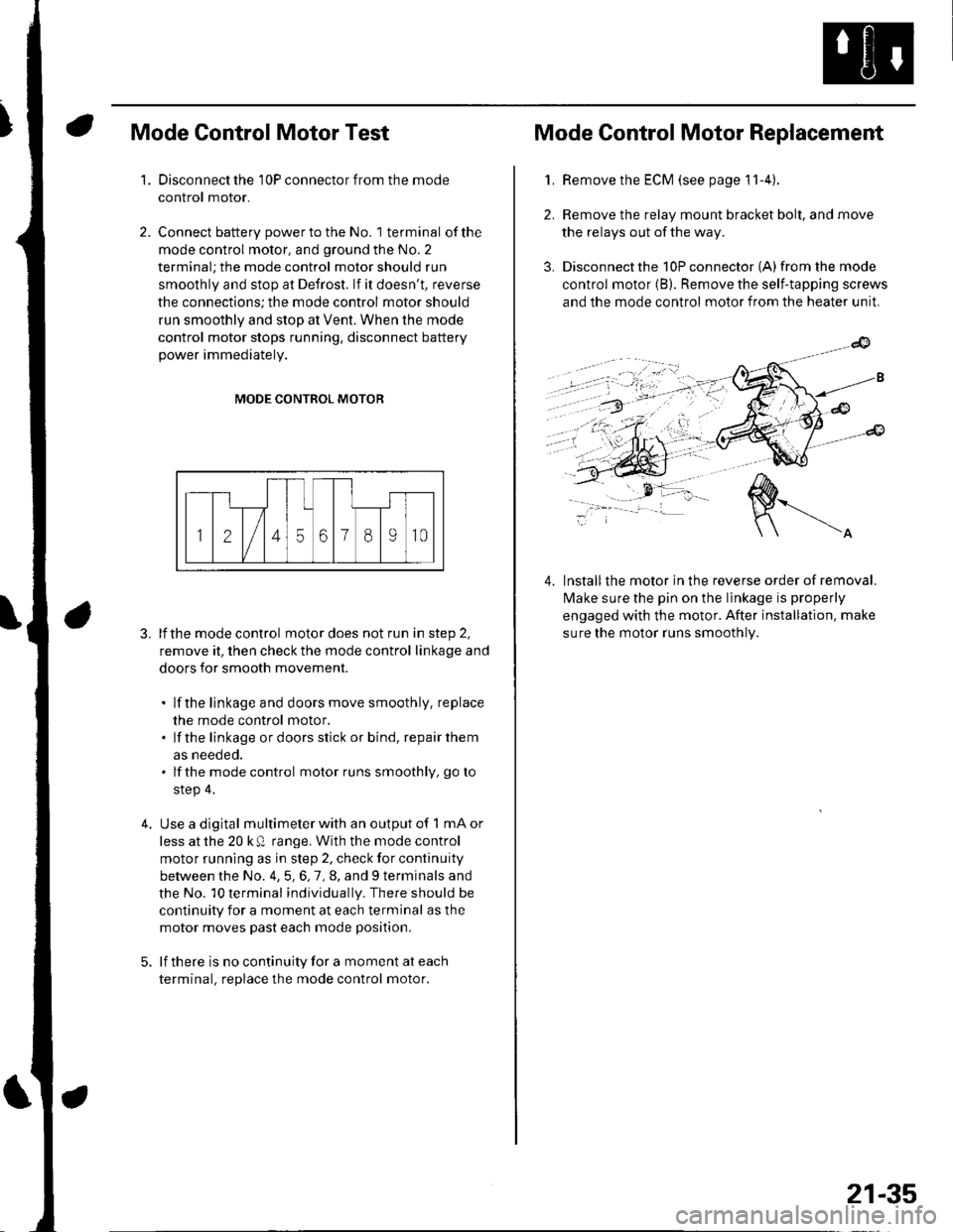
MODE CONTROL MOTOR
3. lfthe mode control motor does not run in step 2,
remove it, then check the mode control linkage and
doors for smooth movement.
. lf the linkage and doors move smoothly. replace
the mode control motor.. lf the linkage ordoorsstick or bind, repairthem
as neeoeo.. lfthe mode control motor runs smoothly, go to
step 4.
Use a digital multimeter with an output of 1 mA or
less at the 20 k Q range. With the mode control
motor running as in step 2, check for continuity
between the No. 4,5,6,7,8, and 9 terminals and
the No. 10 terminal individually. There should be
continuity for a moment at each terminal as the
motor moves past each mode position.
lf there is no continuity for a moment at each
terminal. replace the mode control motor.
Mode Control Motor Replacement
2.
3.
1.Remove the ECM (see page 11-4).
Remove the relay mount bracket bolt, and move
the relays out of the way.
Disconnect the 10P connector {A) from the mode
control motor (B). Remove the self-tapping screws
and the mode control motor from the heater unit.
lnstallthe motor in the reverse order of removal.
lvlake sure the pin on the linkage is properly
engaged with the motor. After installation. make
sure the motor runs smoothly.
4.
21-35
Page 807 of 1139
Heating and Air Conditioning
Recirculation Control Motor Test
1. Disconnect the 5P connector from the recirculation
control motor.
Incorrectly applying power and ground to
the recirculation control motor will damge it.
Follow the instructions carefullv.
2. Connect batterv oower to the No. 5 terminal ofthe
recirculation control motor, and ground the No. 1
and No. 2 terminals; the recirculation control motor
should run smoothly. To avoid damaging the
recirculation control motor, do not reverse power
and ground. Disconnect the No. 1 or No. 2
terminals from ground; the recirculation control
motor should stop at Fresh or Recirculate. Don't
cycle the recirculation control motor {or a long time.
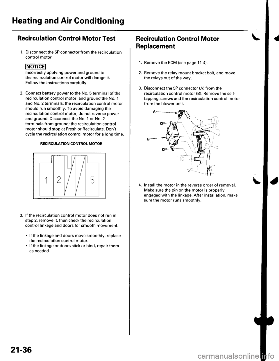
RECIRCULATION CONTROL MOTOR
lf the recirculation control motor does not run in
step 2, remove it, then check the recirculation
control linkage and doors for smooth movement.
. lfthe linkage and doors move smoothly, replace
the recirculation control motor.. lf the linkageordoorsstickor bind, repairthem
as neeoeo.
21-36
Recirculation Control MotorI
Replacement
1.Remove the ECM (see page 11-4).
Remove the relay mount bracket bolt. and move
the relays out of the way,
Disconnect the 5P connector (A) from the
recirculation control motor (B), Remove the self-
tapping screws and the recirculation control motor
from the blower unit.
Installthe motor in the reverse order of removal.
Make sure the pin on the motor is properly
engaged with the linkage. After installation. make
sure the motor runs smoothly.
\
Page 808 of 1139
Evaporator Temperature Sensor
Replacement
1.Remove the driver's dashboard lower cover (see
page 20-59) and the under cover (see page 20-60).
Remove the under-dash fuse/relay box (see page
22-491.
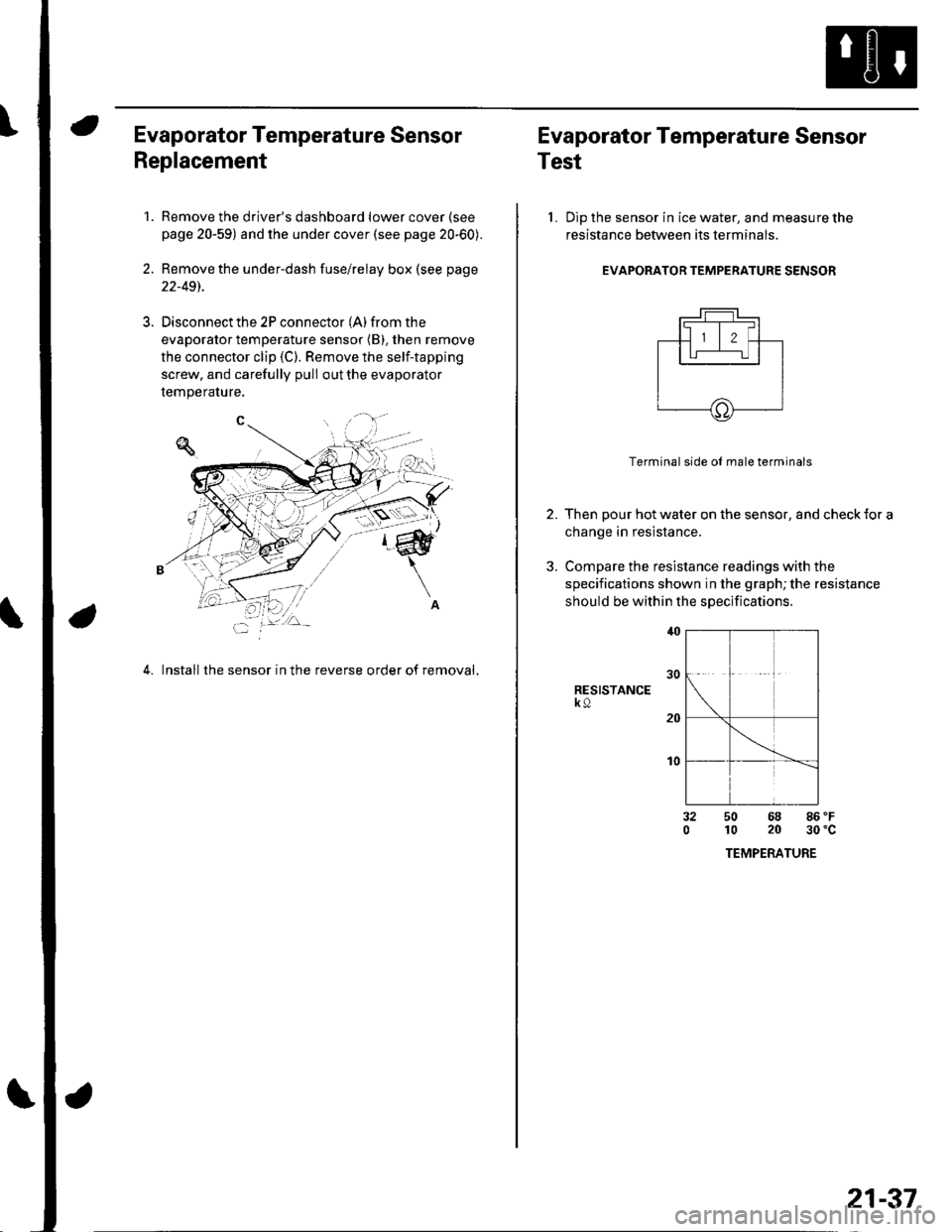
Disconnect the 2P connector (A) from the
evaporator temperature sensor (B), then remove
the connector clip (C). Remove the self-tapping
screw, and carefully pull out the evaporator
temperature.
4. Install the sensor in the reverse order of removal,
Evaporator Temperature Sensor
Test
l. Dip the sensor in ice water, and measure the
resistance between its terminals
EVAPORATOR TEMPERATURE SENSOR
2.
3.
Terminal side ol male terminals
Then pour hot water on the sensor, and check {or a
change in resistance.
Compare the resistance readings with the
specifications shown in the graph; the resistance
should be within the specifications
RESISTANCEk9
t0
32050 68 86 'F
10 20 30'c
TEMPERATURE
21-37
Page 811 of 1139
Heating and Air Gonditioning
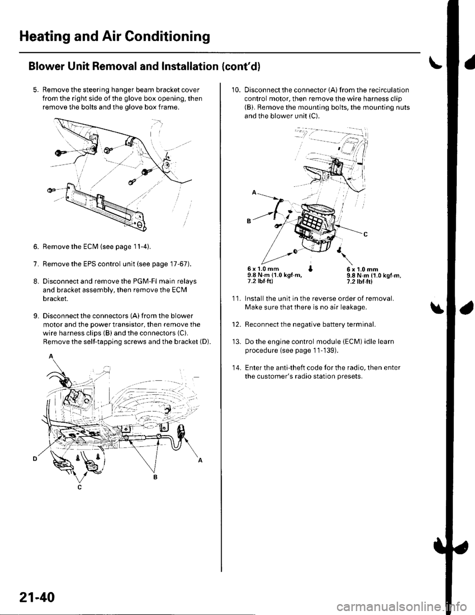
Blower Unit Removal and Installation {cont'd}
Remove the steering hanger beam bracket cover
from the right side of the glove box opening, then
remove the bolts and the olove box frame.
1.
8.
9.
Remove the ECM (see page 11-4).
Remove the EPS control unit (see page 17-67).
Disconnect and remove the PGM-Fl main relays
and bracket assembly, then remove the ECM
bracket.
Disconnect the connectors {A) from the blower
motor and the power transistor, then remove the
wire harness clips (B) and the connectors (C).
Remove the self-tapping screws and the bracket (D).
A
21-40
10. Disconnectthe connector {A) from the recirculation
control motor, then remove the wire harness clip
{B). Remove the mounting bolts, the mounting nuts
and the blower unit (C).
6x 1.0 mm I9.8 N.m (1.0 kgt.m,7.2 tbt.ftl
6x1.0mm9.8 N.m (1.0 kgf.m,?.2 tbf.ft)
11.
14.
Installlhe unit in the reverse order of removal.
Make sure that there is no air leakage.
Reconnect the negative battery terminal.
Do the engine control module (ECM) idle learn
procedure {see page 11-139).
Enter the anti-theft code for the radio, then enter
the customer's radio station presets.
\
'13.
Page 831 of 1139
\Body Electrical
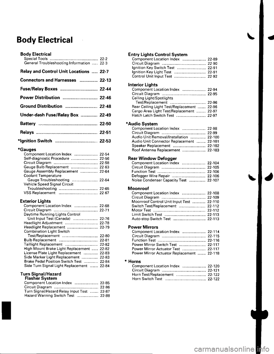
Body ElectricalSpecialToolsGeneral Troubleshooting tntorrnaiion.'......
Relay and Control Unit Locations .....
Connectors and Harnesses
Fuse/Relay Boxes ...............................
Power Distribution .............................
Ground Distribution ...........................
Under-dash Fuse/Relay Box ..............
Battery ..............
Relays ................
*lgnition Switch ..............
*Gauges
Component Location Index .......................Self-diagnostic Procedure ..........................Circuit DiagramGauge Bulb Replacement ..........................Gauge Assembly ReplacementCoolant Temperature
Gauge Troubleshooting .... ....................Vehicle Speed Signal CircuitTroubleshootingVSS Replacement
Exterior LightsComponent Location Index .......................Circuit DiagramDaytime Running Lights ControiUnit Input Test (Canada) ........................Headlight Ad,ustment .................. .. .....Headlighr Replacement ..............................Combination Light SwitchTest/ReplacementBulb ReplacementTaillight Replacement ..........................High Mount Brake Light Replacement ......License Plate Light Replacement ..............Side Marker Light Replacement ................Brake Pedal Position Switch Test ..............Side Turn Signal Light Replacement ........
Turn Signal/HazardFlasher SystemComponent Location Index .......................Circuit DiagramTurn Signal/Hazard Relay lnputTest ........Hazard Warning Switch Test
22,3
22-7
22-13
22-44
22-46
22-4A
22-49
22-50
22-51
22-53
22-5422-5622-5422 6322-64
22-64
22-6522 61
22-6822--71
22-7 622-7422-79
22-AO22-4122-8222-4222-4322-4322-4422-84
22-8�522 A622-8722-88
22-10422-105
22-10622-107
Entry Lights control systemComponent Location Index ....................... 22-89Circuit Diagram ......... 22 90lgnition Key Switch Test .....................,...... 22-9'llgnition Key Light Test ............................... 22-91Control Unit Input Test ..........,.................... 22 92
Interior LightsComponent Location Index ....................... 22-94Circuit Diagram ......... 22-95Ceiling LighVSpotlightsTesVReplacement ................................... 22-96Rear Ceiling Light TesVReplacem ent ........ 22-96Cargo Area Light Test/Replacem ent ......... 22-97Hatch Latch Switch Test ..,..,....................... 22-97
*Audio SystemComponent Location Index ....................... 22-98Circuit Diagram ......... 22,99Audio Unit Removal/lnstallation ............... 22-1OOAudio Unit Connector Replacement ......... 22-101Speaker Replacement ................................ 22-102Roof Antenna Rep1acement ....................-.. 22-103
Rear Window DefoggerComponent Location Index ...........Circuit Diasram .. ....... .. ..... ....... ...:::::.::.::.Function TestDefogger Wire Repair .................................Noise Condenser CapacityTest ................
MoonroofComponent Location Index ....................... 22-1OBCircuit Diagram ......... 22-109Moonroof Control Unit Input Test ............. 22-'l10Switch TesVReplacement ........,.....,........... 22-1 12Motor Test ................. 22-112Limit Swilch Test ...... 22-'l'13Auto-stop Switch Test ................................ 22-1 13
Power MirrorsComponent Location Index ....................... 22-114Circuit Diagram ......... 22-115Function Test ............. 22-116Power Mirror Switch Test .......................... 22-ll7Power Mirror Actuator Test ....................... 22-117Power Mirror Actuator Replacement ........ 22-11A
* HornsComponent Location Index ....................... 22-120Circuit Diagram ......... 22-121Horn TesVReplacement ...........................-. 22-122Horn Switch Test .,.... 22-122
\