relay HONDA CIVIC 2003 7.G Manual PDF
[x] Cancel search | Manufacturer: HONDA, Model Year: 2003, Model line: CIVIC, Model: HONDA CIVIC 2003 7.GPages: 1139, PDF Size: 28.19 MB
Page 776 of 1139
Heating and Air Conditioning
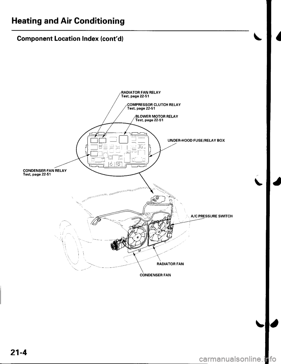
Component Location Index (cont'dl
CONDENSER FANTest, page 22-51
RADIATOR FAN RELAYTest, page 22-51
Tesl, page 22-51CLUTCH RELAY
MOTOR RELAYTest, page 22-5I
UNDER.HOOD FUSE/RELAY BOX
... A/C PRESSURE SWITCH
RADIATOR FAN
\
.\
-
'-t t_]]l
/l I T I --::--
l- -l -
CONOENSER FAN
21-4
Page 782 of 1139
Heating and Air Conditioning
{
a
a
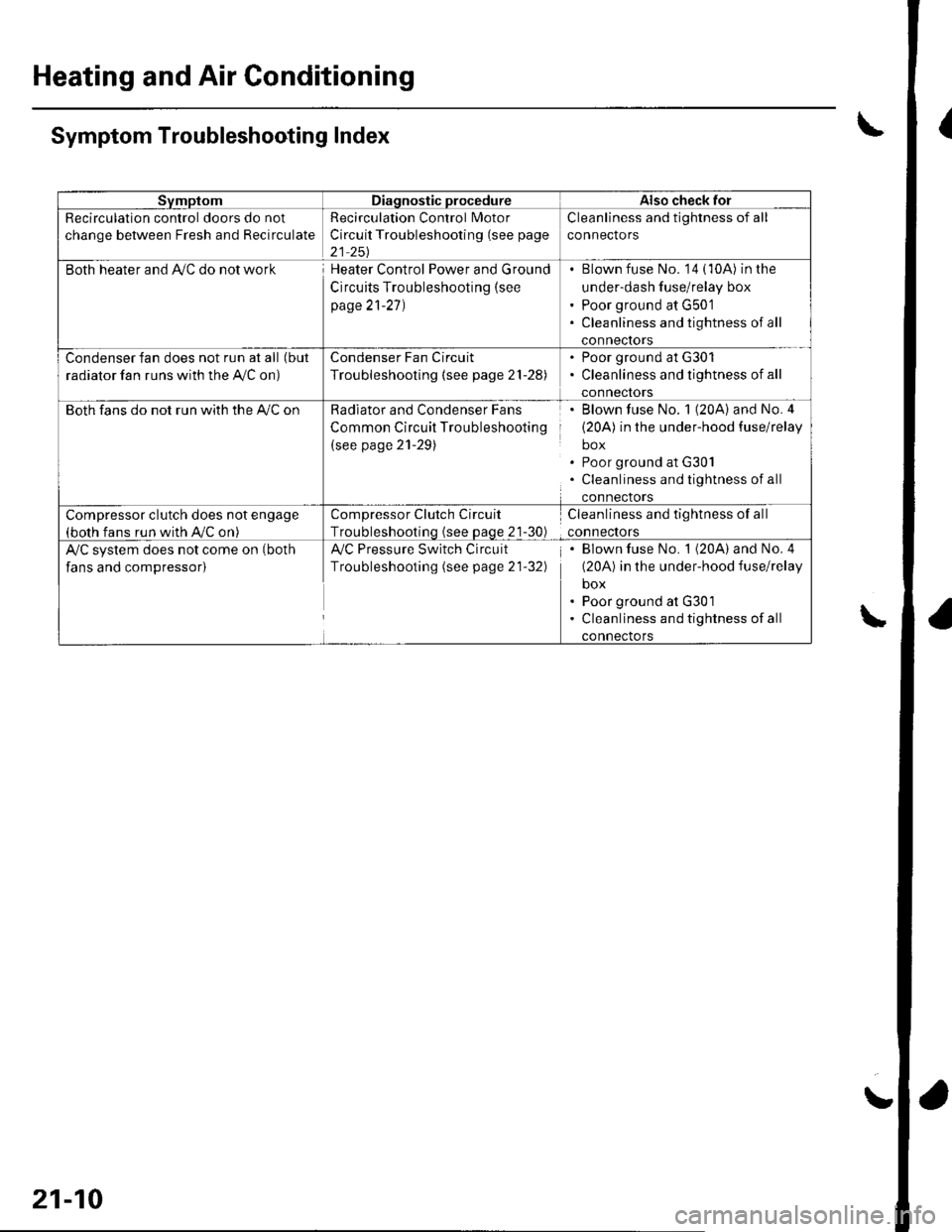
SvmptomDiagnostic procedureAlso check for
Recirculation control doors do not
change between Fresh and Recirculate
Recirculation Control Motor
Circuit Troubleshooting (see page
21 251
Cleanliness and tightness of all
connectors
Both heater and Ay'C do not workHeater Control Power and Ground
Circuits Troubleshooting (see
page 21-27)
Blown fuse No. '14 (10A) in the
under-dash fuse/relay box
Poor ground at G501
Cleanliness and tightness of all
conneclors
Condenser fan does not run at all (but
radiator fan runs with the Ay'C on)
Condenser Fan Circuit
Troubleshooting {see page 21-28)
. Poor ground at G301. Cleanliness and tightness of all
connectors
Both fans do not run with the A,/C onRadiator and Condenser Fans
Common Circuit Troubleshooting
(see page 21-29)
Blown fuse No. 1 (20A) and No.4
(20A) in the under-hood fuse/relay
box
Poor ground at G30l
Cleanliness and tightness of all
connectors
Compressor clutch does not engage(both fans run with A,/C on)
Compressor Clutch Circuit
Troubleshootinq (see Daqe 21-30)
Cleanliness and tightness of all
connectors
A/C system does not come on (both
fans and compressor)
Ay'C Pressure Switch Circuit
Troubleshooting (see page 21-32)
Blown fuse No. 1 (20A) and No. 4
(20A) in the under-hood fuse/relay
box
Poor ground at G301
Cleanliness and tightness of all
connectors
\Symptom Troubleshooting Index
\
21-10
!
Page 783 of 1139
System Description
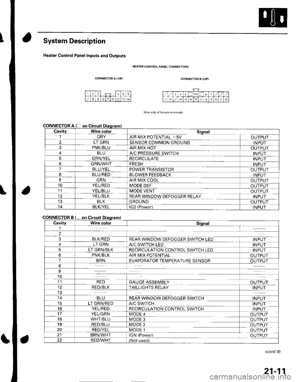
Heater Control Panel Inputs and Outputs
CONNECTOR A {r/rP)
CONNECTOR
CONNECTOR
HEATER CONTFOL PANEL CONNECIORS
CONNECTOR B (22P)
W re s de oitema eterm nals
Cavity Wire color_| \ln YAIR MIX POTENTIAL +5V
Sional
OUTPUT2LT GRNSENSOR COMMON GROUNDINPUT3PNK/BLUAIR MIX HOTOUTPUTBLUA,/C PRESSURE SWITCHINPUT5GRNA/ELRECIRCULATEINPUT6GRNA/VHTFRESHINPUT7BLUI/ELPOWER TRANSISTOROUTPUT8BLU/REDBLOWER FEEDBACKINPUTIGRNAIR MIX COOLOUTPUT10YEL/REDMODE DEFOUTPUT11. YEVBTU
YEL/BLK
MODE VENT
REAR WINDOW DEFOGGER RELAY
OUTPUT
INPUTBLKGROUNDOUTPUT14B LK/YELlG2 (Power)INPUT
Bon
CavityWire colorSiqnal1--T
2
3BLIVREDREAR WINDOW DEFOGGER SWITCH LEDINPUT
4LT GRNA./C SWITCH LEDINPUT
5LT GRN/BLKRECIRCULATION CONTROL SWITCH LEDINPUT
6PNVBLKAIR MIX POTENTIALOUTPUT
7BRNEVAPORATOR TEIMPERATURE SENSOROUTPUT
8
9
10
GAUGE ASSEMBLYal' 'TDr ri11RED
RED/BLKTAILLIGHTS RELAYINPUT
14BLUREAR WINDOW DEFOGGER SWITCHINPUTicLT GRN/REDA/C SWITCHINPUT16YEVREDRECIRCULATION CONTROL SWITCHINPUT17YEUGRNMODE 4OUTPUT18WHT/BLUMODE 3OUTPUT19RED/BLUMODE 2OUTPUT20RED/YELMODE 1OUTPUTBRN^,^/HTIGN (PowedOUTPUT22R E DA/r'HT(Not used)
(cont'd)
21-11
Page 791 of 1139
Heating and Air Gonditioning
DTC Troubleshooting {cont'd)
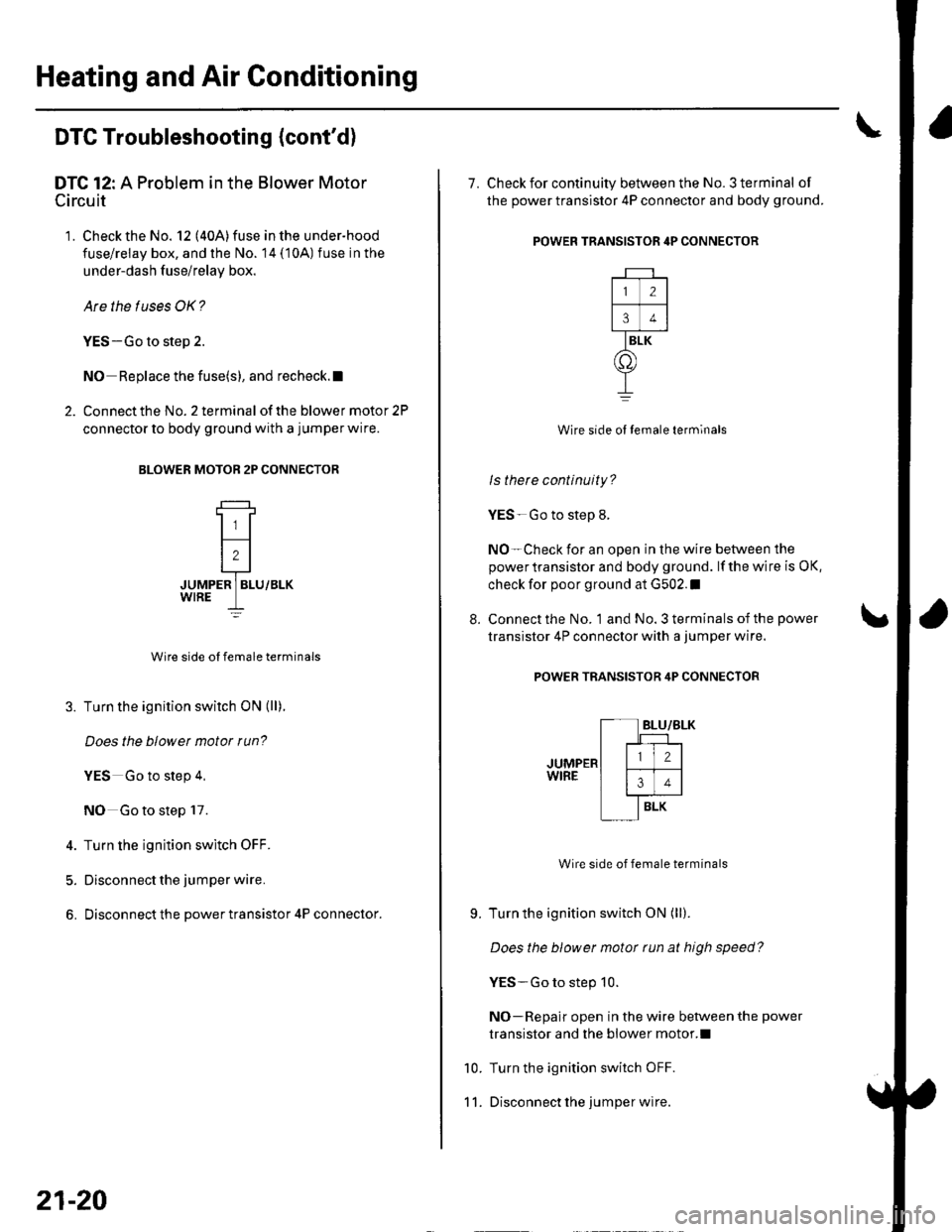
DTC 12: A Problem in the Blower Motor
Circuit
'1. Check the No. 12 (40A)fuse inthe under-hood
fuse/relay box, and the No. 14 (10A) fuse in the
under-dash f use/relay box.
Are the tuses OK?
YES-Go to step 2.
NO Replace the fuse(s), and recheck.l
2. Connect the No. 2 terminal of the blower motor 2P
connector to body ground with a jumper wire.
BLOWER MOTOB 2P CONNECTOR
JUMPER ] BLU/BLK
Wire side ol female terminals
3. Turn the ignition switch ON (ll).
Does the blowet motor run?
YES Go to step 4,
NO Go to step 17.
4. Turn the ignition switch OFF.
5. Disconnect the jumper wire.
6. Disconnect the power transistor 4P connector.
21-20
8.
7. Check for continuity between the No. 3 terminal of
the power transistor 4P connector and body ground.
POWER TRANSISTOR 4P CONNECTOR
Wire side ol temale terminals
ls there continuity?
YES-Go to step 8.
NO-Check for an open in the wire between the
power transistor and body ground. lf the wire is OK,
check for poor ground at G502.I
Connect the No. 1 and No. 3 terminals of the power
transistor 4P connector with a jumper wire.
POWER TRANSISTOR 4P CONNECTOR
Wire side of female terminals
Turn the ignition switch ON (ll).
Does the blower motor tun at high speed?
YES-Go to step 10.
NO-Repair open in the wire between the power
transistor and the blower motor.l
Turn the ignition switch OFF.
Disconnect lhe jumper wire.
9.
10.
11.
2
34
BLK
o
Page 792 of 1139
1a
13.
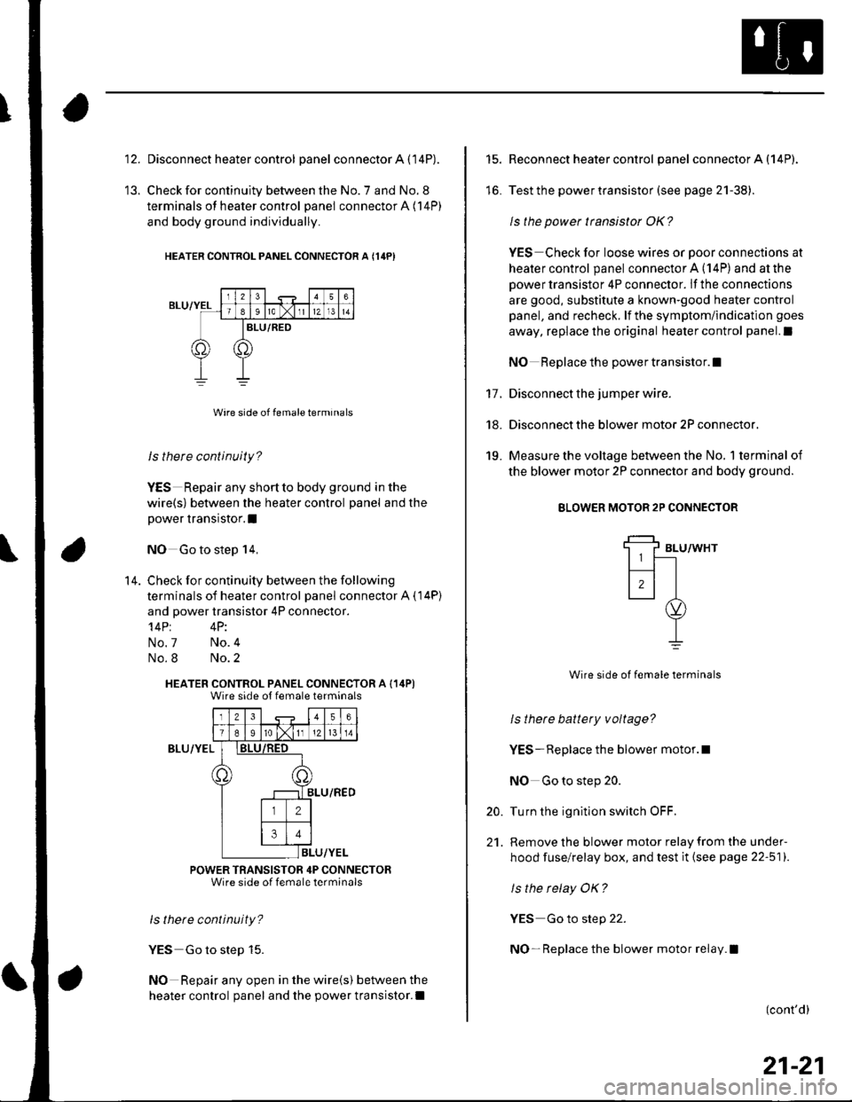
Disconnect heater control panel connector A (14P).
Check for continuity between the No. 7 and No. 8
terminals of heater control panel connector A (14P)
and body ground individually.
HEATER CONTNOL PANEL CONNECTOR A {14PI
ls there continuity?
YES Repair any shortto body ground in the
wire(s) between the heater control panel and the
power transistor.I
NO Go to step 14,
Check for continuity between the following
terminals of heater control panel connector A ( 14P)
and power transistor 4P connector.'l4Pt 4P:
No.7 No.4
No.8 No.2
HEATER CONTROL PANEL CONNECTOR A (14P)Wire side ot female terminals
Iz341516
T89ro lxlI12l 13 l 14
)8LU/RED
ILU/YEL
POWER TRANSISTOR 4P CONNECTORWire side of female terminals
ls thete continuity?
YES Go to step 15.
NO Repair any open in the wire(s) between the
heater control panel and the power transistor.l
14.
BLU/YEL
15.
lo.
17.
18.
19.
Reconnect heater control panel connector A (14P).
Test the power transistor (see page 21-38).
ls the power transistor OK?
YES Check for loose wires or poor connections at
heater control panel connector A (14P) and at the
power transistor 4P connector. lf the connections
are good, substitute a known-good heater control
panel, and recheck. lf the symptom/indication goes
away, replace the original heater control panel.l
NO Replace the power transistor.I
Disconnect the jumper wire.
Disconnect the blower motor 2P connector.
Measure the voltage between the No, 1 terminal of
the blower motor 2P connector and body ground.
BLOWER MOTOR 2P CONNECTOR
BLU/WHT
Wire side of female terminals
ls thete battery voltage?
YES- Replace the blower motor.l
NO Go to step 20.
Turn the ignition switch OFF.
Remove the blower motor relay from the under-
hood fuse/relay box, and test it (see page 22-511.
ls the relay OK?
YES Go to step 22.
NO- Replace the blower motor relay.l
20.
21.
(cont'd)
21-21
Page 793 of 1139
Heating and Air Conditioning
DTC Troubleshooting lcont'd)
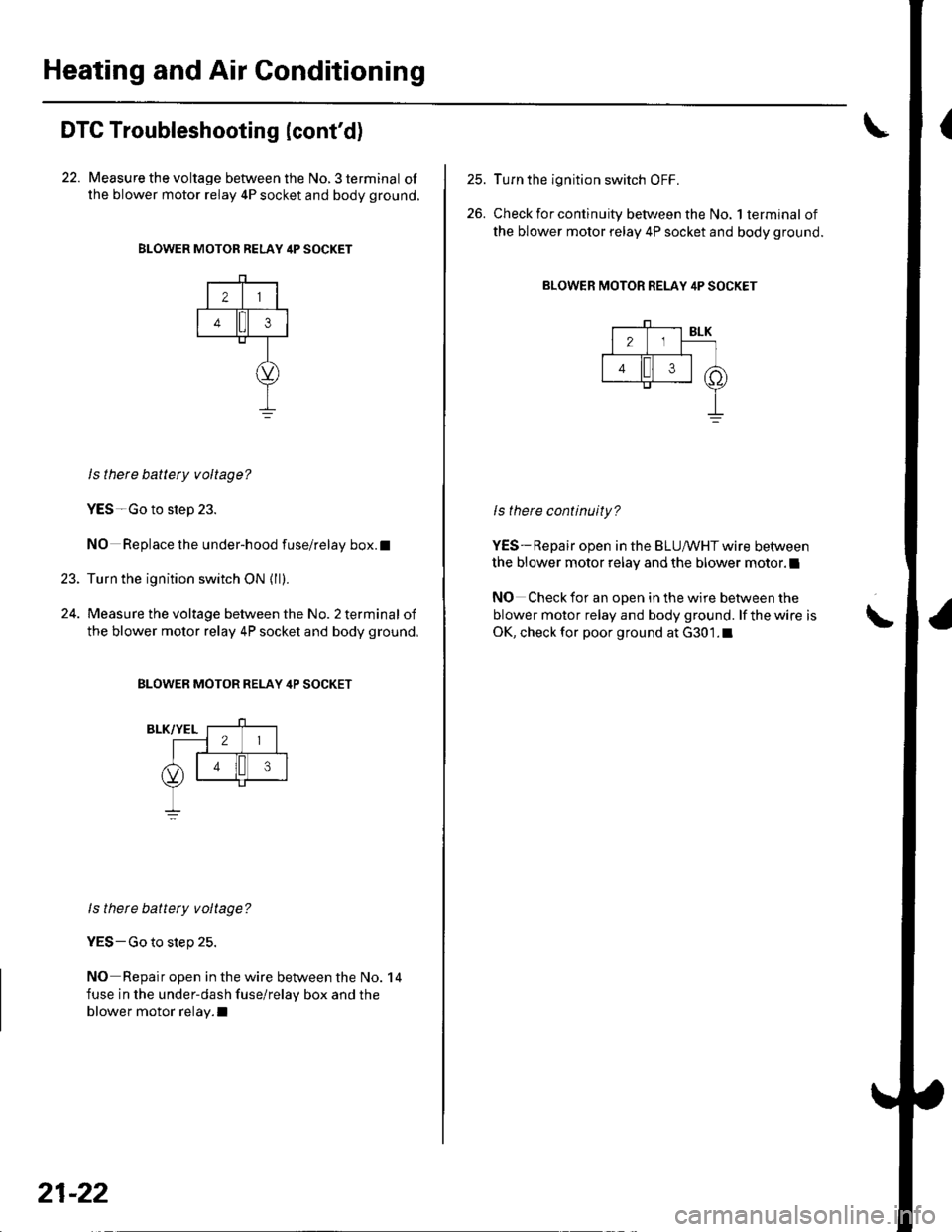
22. Measure the voltage between the No. 3 terminal of
the blower motor relay 4P socket and body ground.
BLOWER MOTOR RELAY 4P SOCKET
21
43
23.
ls there battety voltage?
YES-Go to step 23.
NO Replace the under-hood fuse/relay box.t
Turn the ignition switch ON {ll).
Measure the voltage between the No. 2 terminal of
the blower motor relay 4P socket and body ground,
BLOWER MOTOR RELAY 4P SOCKET
ls there battery voltage?
YES-Go to step 25.
NO Repair open in the wire between the No. 14
fuse in the under-dash fuse/relay box and the
blower motor relay.I
21-22
25.
26.
Turn the ignition switch OFF,
Check for continuity between the No. 1 terminal of
the blower motor relay 4P socket and body ground.
BLOWER MOTOR RELAY 4P SOCKET
ls there continuity?
YES-Repair open in the BLUIr'/HT wire between
the blower motor relay and the blower motor.l
NO Check for an open in the wire between the
blower motor relay and body ground. lf the wire is
OK, check for poor ground at G301.1\
Page 796 of 1139
3.
Recirculation Control Motor Circuit Troubleshooting
1. Check the No. 14('10A)fuse inthe under-dashfuse/
relay box.
ls the f use OK?
YES Go to step 2.
NO- Replace the fuse, and recheck.l
2. Disconnect the recirculation control motor 5P
conneclor.
Turn the ignition switch ON (ll).
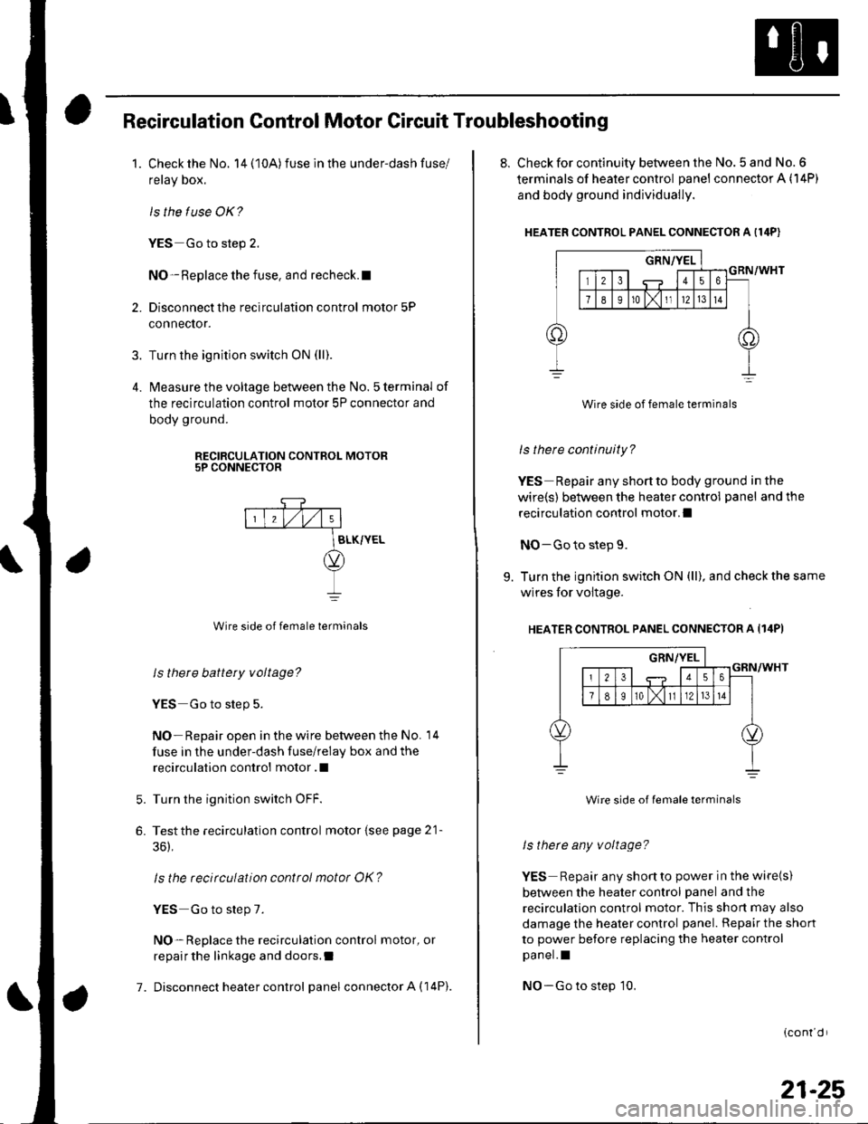
lvleasure the voltage between the No. 5 terminal of
the recirculation control motor 5P connector and
body ground.
RECIRCULATION CONTROL MOTOR5P CONNECTOR
7.
Wire side of female terminals
ls there battery voltage?
YES Go to step 5.
NO- Repair open in the wire between the No. 14
fuse in the under-dash fuse/relay box and the
recirculation control motor .l
Turn the ignition switch OFF.
Testthe recirculation control motor {see page 21-
36),
ls the recirculation control motor OK?
YES Go to step 7.
NO- Replace the recirculation control motor, or
repair the linkage and doors.I
Disconnect heater control panel connector A (14P).
5.
6.
8. Check for continuity between the No. 5 and No. 6
terminals of heater control panel connector A (14P)
and body ground individually.
HEATER CONTROL PANEL CONNECTOR A I14P)
Wire side of female terminals
ls there continuity?
YES Repair any shortto body ground in the
wire(s) between the heater control panel and the
recirculation control motor.l
NO-Go to step 9.
9. Turn the ignition switch ON (ll), and check the same
wires for voltage.
HEATER CONTROL PANEL CONNECTOR A Il4PI
Wire side of lemale terminals
ls therc any voltage?
YES Repair any shonto power in the wire(s)
between the heater control panel and the
recirculation control motor. This shon may also
damage the heater control panel. Repair the shon
to power before replacing the heater control
pa nel. I
NO-Go to step 10.
{cont d r
21-25
Page 798 of 1139
Heater Control Power and Ground Circuits Troubleshooting
1. Check the No.14 (10A)fuse in the under-dash
fuse/relay box.
ls the f use OK?
YES-Go to step 2.
NO-Replace the fuse, and recheck.l
2. Disconnect heater control panel connectorA{'14P).
3. Turn the ignition switch oN (ll).
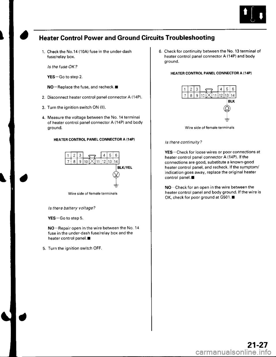
4. Measure the voltage between the No. l4terminal
of heater control panel connector A (14P) and body
grouno.
HEATER CONTROL PANEL CONNECTOR A {14P}
23456
78I10 l,111214
Wire side of temale terminals
BLK/YEL
ls there battery voltage?
YES-Go to step 5.
NO Repair open in the wire betvveen the No. 14
fuse in the under-dash fuse/relay box and the
heater control panel.l
Turn the ignition switch OFF.
6. Check for continuity between the No. l3terminal of
heater control panel connector A (14P) and body
g rou nd.
HEATER CONTRoL PANEL CONNEcToR A (1ilP)
123456
I89r0 t,1l1214
BLK
.o
Wire side of temaleterminals
ls therc continuity?
YES Check for loose wires or poor connections at
healer control panel connector A (14P). lfthe
connections are good, substitute a known-good
heater control panel, and recheck. lf the symptom/
indication goes away, replace the original heater
control panel.l
NO Check for an open in the wire between the
heater control panel and body ground. lf the wire is
OK, check for poor ground at G501. I
21-27
Page 799 of 1139
Heating and Air Conditioning
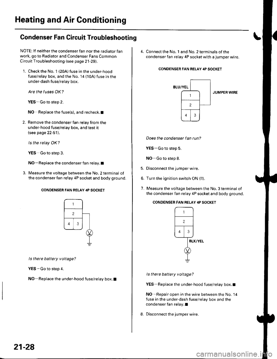
Condenser Fan Circuit Troubleshooting
NOTE: lf neither the condenser fan nor the radiator fan
work, go to Radiator and Condenser Fans Common
Circuit Troubleshooting (see page 21-29).
1. Check the No. 1 (20A) fuse in the under-hood
fuse/relay box, and the No. 14 (10A)fuse in the
under-dash f use/relay box.
Are the tuses OK?
YES-Go to step 2.
NO Replace the fuse(s), and recheck. t
2. Remove the condenser fan relay from the
under-hood fuse/relay box, and test it(see page 22-51).
ls the relay OK?
YES Go to step 3.
NO- Replace the condenser fan relay.l
3. Measure the voltage between the No, 2 terminal of
the condenser fan relay 4P socket and body ground.
CONDENSER FAN RELAY ilP SOCKET
ls thete battery voltage?
YES-Go to step 4.
NO-Replace the under-hood fuse/relay box.l
21-28
4. Connect the No. landNo.2terminalsof the
condenser fan relay 4P socket with a jumper wire.
CONDENSER FAN RELAY itP SOCKET
JUMPER WIRE
Does the condenser lan tun?
YES-Go to step 5.
NO Go to step 8.
5. Disconnect the jumper wire.
6. Turn the ignition switch ON (ll).
7. Measure the voltage between the No, 3 terminal of
the condenser fan relay 4P socket and body ground.
ls there battery voltage?
YES Replace the under-hood fuse/relay box.t
NO-Repair open in the wire between the No. 14
fuse in the under-dash fuse/relay box and the
condenser fan relay.l
Disconnect the jumper wire.
CONDENSER FAN FELAY 4P SOCKET
r-,_-l
12 |
Flr\----1--rl
IELK/YEL
d,
I
Page 800 of 1139
9.
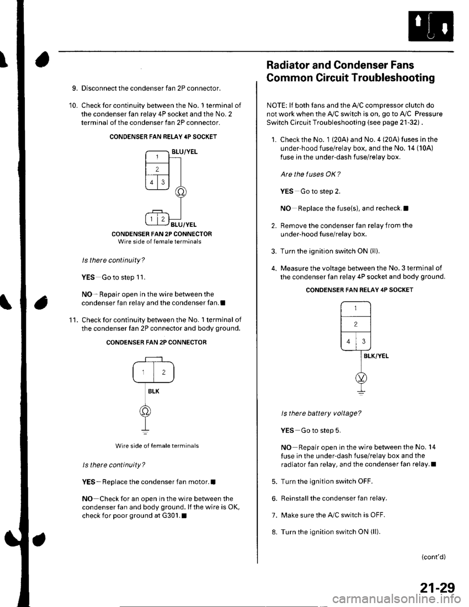
10.
Disconnect the condenser fan 2P connector,
Check for continuity between the No. 1 terminal of
the condenser fan relay 4P socket and the No. 2
terminal of the condenser fan 2P connector.
CONDENSER FAN RELAY 4P SOCKET
CONDENSER FAN 2P CONNECTORWire side of female terminals
Is there continuity?
YES Go to step 1 1.
NO- Repair open in the wire between the
condenser fan relay and the condenser fan,I
Check for continuity between the No. 1 terminal of
the condenser fan 2P connector and body ground.
CONDENSER FAN 2P CONNECTOR
12
BLK
o
Wire side of {emale terminals
ls there continuity?
YES- Replace the condenser fan motor.I
NO Check for an open in the wire between the
condenser fan and body ground. lf the wire is oK,
check for poor ground at G301.1
'11 .
Radiator and Condenser Fans
Common Circuit Troubleshooting
NOTE; lf both fans and the Ay'C compressor clutch do
not work when the Ay'C switch is on, go to Ay'C Pressure
Switch Circuit Troubleshooting (see page 21-32l, .
1. Check the No. 1 {20A} and No. 4 (20A) fuses in the
under-hood fuse/relay box, and the No. 14 (10A)
fuse in the under-dash fuse/relay box.
Are the tuses OK?
YES Go to steD 2.
NO Replace the fuse(s), and recheck.l
2. Remove the condenser fan relav from the
under-hood f use/relay box.
3. Turn the ignition switch ON (ll;.
4. Measure the voltage between the No. 3 terminal of
the condenser fan relay 4P socket and body ground.
ls there battery voltage?
YES Go to step 5.
NO Repair open in the wire between the No. 14
fuse in the under-dash fuse/relay box and the
radiator fan relay, and the condenser fan relay.l
5. Turn the ignition switch OFF.
6. Reinstall the condenser fan relay.
7. Make sure the IVC switch is OFF.
8. Turn the ignition switch ON (ll).
(cont'd)
CONDENSER FAN RELAY 4P SOCKET
r-,
-l
12lf---r---
l,l,l
lar-vver-
l
o
I
21-29