HONDA CIVIC 2003 7.G Workshop Manual
CIVIC 2003 7.G
HONDA
HONDA
https://www.carmanualsonline.info/img/13/5744/w960_5744-0.png
HONDA CIVIC 2003 7.G Workshop Manual
Trending: headlight, injector voltage, vtc strainer, light, Diesel, length, alternator belt
Page 171 of 1139
Engine Oil Replacement
Warm up the engine.
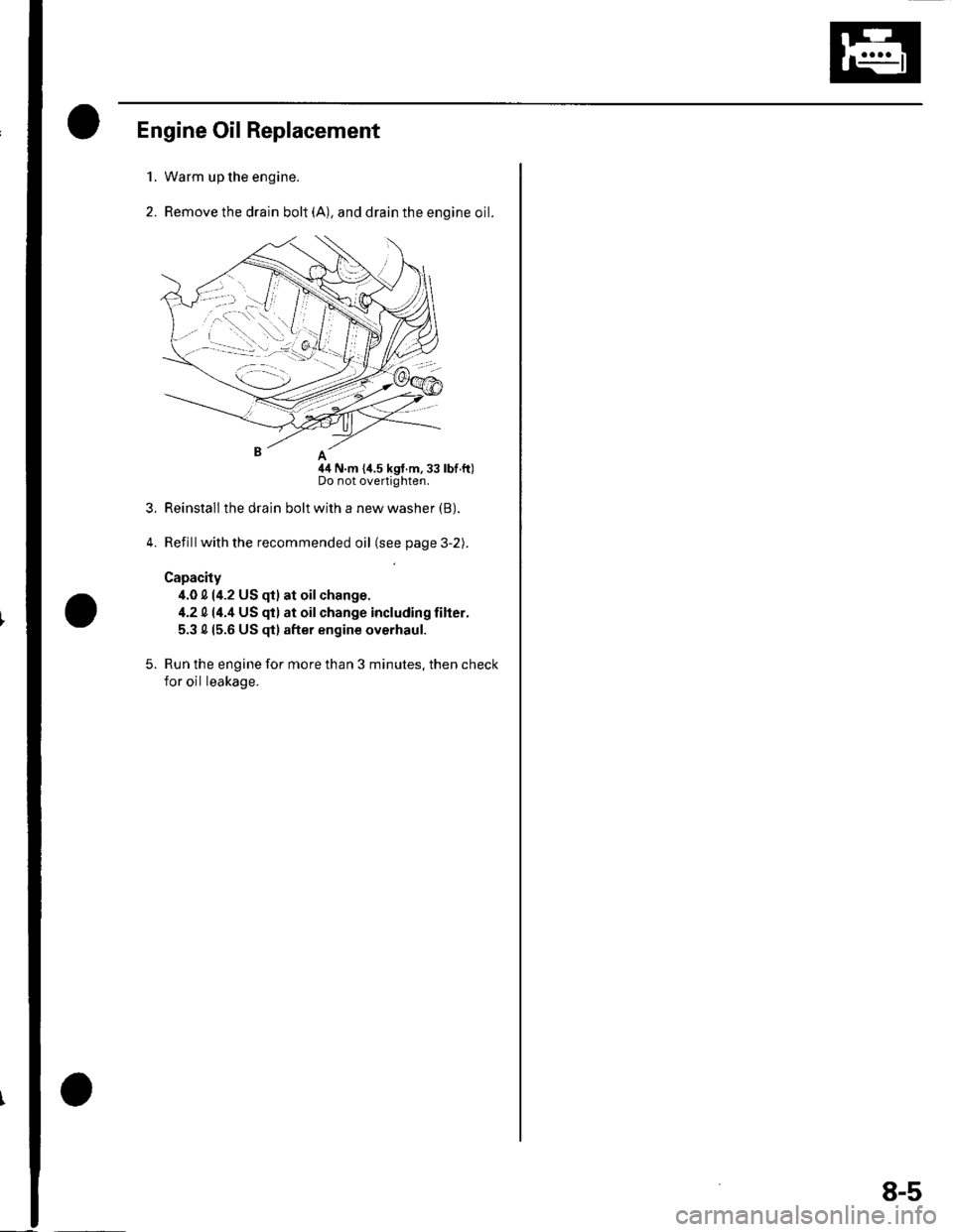
Remove the drain bolt (A), and drain the engine oil.
nA
44 N.m {i1.5 kgf.m,33 lbf.ft)Do not overtighten.
Reinstall the drain bolt with a new washer (B).
Refillwith the recommended oil (see page 3-2).
Capacity
4.0 0 (4.2 US qt) at oilchange.
4.2 014.4 US qt) at oilchange including filter.
5.3 015.6 US $) after engine overhaul.
Run the engine for more than 3 minutes. then check
for oil leakage.
1.
2.
3.
5.
8-5
Page 172 of 1139
Engine Lubrication
Engine Oil Filter Replacement
Special Tool Fequired
Oil filter wrench 07HAA-PJ70100
Engine Oil Filter (3/4-turn type)
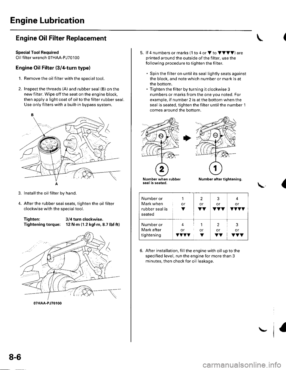
1. Remove the oil filterwiththesDecial tool.
2. Inspect the threads {A) and rubber seal (B) on the
new filter. Wipe off the seat on the engine block,
then apply a light coat of oil to the filter rubber seal.
Use only filters with a built-in bypass system.
Installthe oilfilter by hand.
After the rubber seal seats, tighten the oil filter
clockwise with the special tool.
Tighten: 3/4 turn clockwise.
Tightening torque: 12 N.m (r.2 kgf.m,8.7 lbf.ft)
07HAA-PJ70100
8-6
\,
5. lf 4 numbers or marks (1 to 4 or V to VVVV) are
printed around the outside of the filter, use the
following procedure to tighten the filter.
. Spin the filter on until its seal lightly seats against
the block, and note which number or mark is at
the bottom.. Tighten the filter by turning it clockwise 3
numbers or marks from the one you noted. For
example, if number 2 is at the bottom when the
seal is seated, tighten the filter until the number 1
comes around the bottom.
Number when rubberseal is seated.Number after tightening.
(\..
6. After installation, fill the enginewith oil uptothe
specified level, run the engine for more than 3
minutes, then check for oil leakage.
Number or
Mark when
rubber seal is
1
or
V
2
or
VV
3
or
VVV
4
or
VVVV
Number or
Mark after
tightening
41
or or
vvvv. v
2
or
VV
3
or
VVV
Page 173 of 1139
Oil Filter Feed Pipe Replacement
1.Remove the oilfilter (see page 8-6).
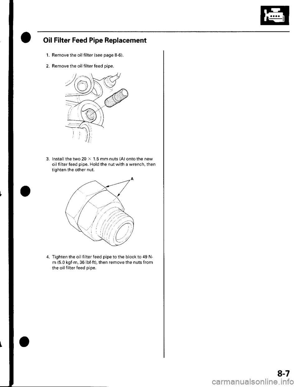
Remove the oil filter feed pipe.
3. lnstallthetwo20 x 1.5mmnuts(A) ontothenew
oil filter feed pipe. Hold the nut with a wrench, then
tighten the other nut.
4. Tightenthe oil filterfeed pipetothe blockto 49 N.
m {5.0 kgf.m, 36 lbf ft), then remove the nuts from
the oil filter feed oiDe.
8-7
Page 174 of 1139
Engine Lubrication
OilPump Overhaul
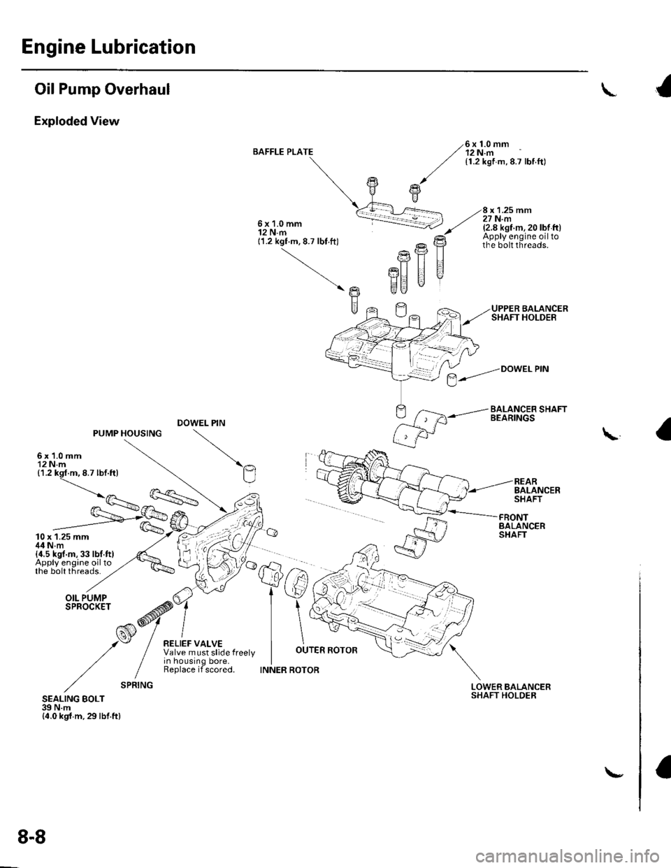
Exploded View
BAFFLE PLATE6x1.0mm12 N.m{1.2 kgf m,8.7 lbf.ft)
x 1.25 mm27 N.m6x1.0mm12 N.m11.2 kgf.m, 8.7 lbt ft)
(2.8 kst m, 20 lbt ft)Apply engine oiltothe bolt threads.
UPPER BALANCERSHAFT HOLDER
BALANCER SHAFTBEARINGS
Ptr
PU II
EU "
DOWEL PIN
REARBALANCERSHAFT
\
- /=.---'n
fs/
tw
FRONTBALANCERSHAFT
LOWERSHAFTBALANCERHOLDERSEALING BOLT39 N.m{4.0 kgf.m,29lbf.ftl
$--."Dowetem
8-8
\-
Page 175 of 1139
Oil Pump Removal
1. Setthe No. 1 piston attop dead center {TDC) {see
step 1 on page 6-12).
2. Remove the oil pan(seepageT-11).
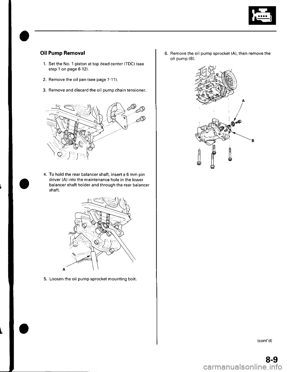
3. Remove and discard the oil pumpchaintensioner.
4. To hold the rear balancer shaft, insert a 6 mm pin
driver (A) into the maintenance hole in the lower
balancer shaft holder and through the rear balancer
shaft.
5. Loosen the oil pump sprocket mounting bolt.
6. Remove the oil pump sprocket (A), then remove the
oil pump (B).
(cont'd)
8-9
Page 176 of 1139
Engine Lubrication
Oil Pump Overhaul {cont'dl
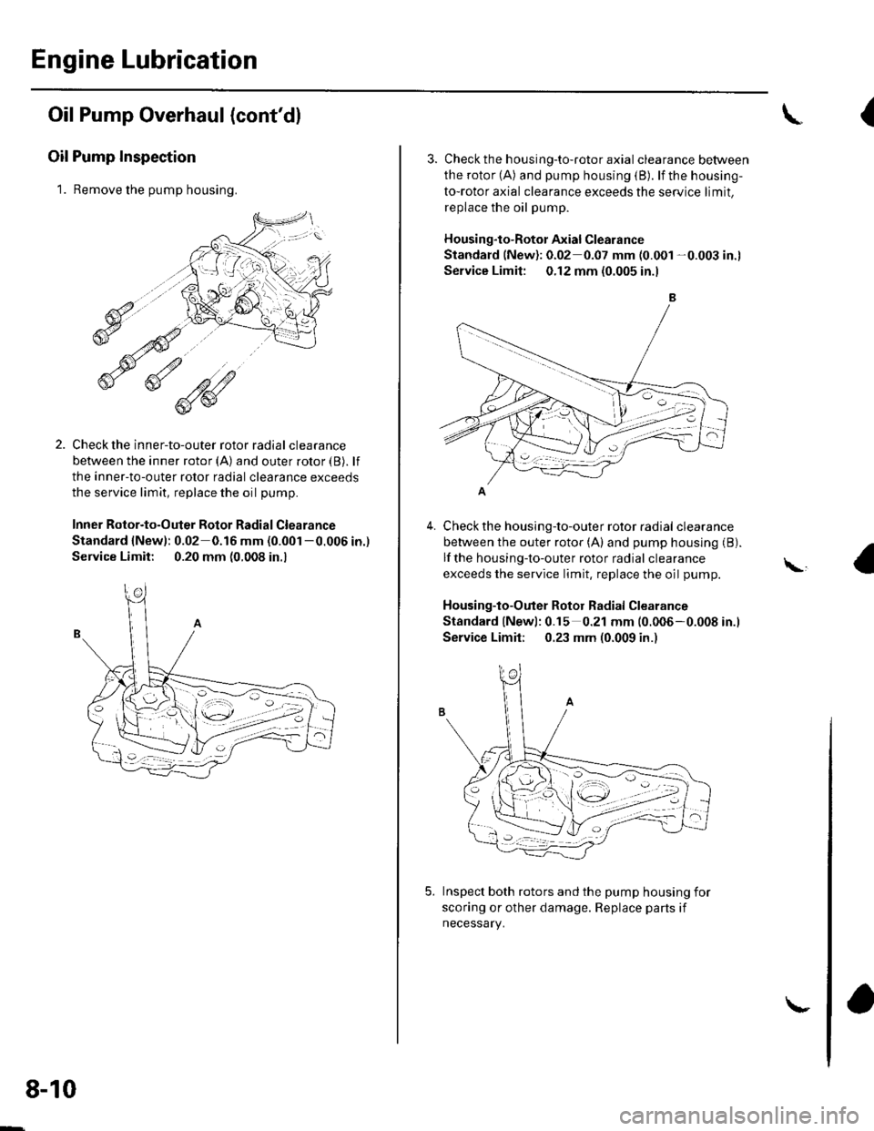
Oil Pump Inspection
1. Remove the pump housing.
Check the inner-to-outer rotor radial clearance
between the inner rotor (A) and outer rotor {B). lf
the inner-to-outer rotor radial clearance exceeds
the service limit, replace the oil pump.
Inner Rotor-to-Outer Botor Radial Clearance
Standard {New): 0.02 0.16 mm (0.001 -0.006 in.)
Service Limit: 0.20 mm (0.008 in.,
1'[1e-\1.-,-2
1 'a - :.: ,-'r'
8-10
\-
{
4.
3. Check th e h ousing-to-roto r axia I clearance between
the rotor (A) and pump housing (B). lf the housing-
to-rotor axial clearance exceeds the service limit.
replace the oil pump.
Housing"to-Rotor Axial Clearance
Standard (New): 0.02 0.07 mm (0.001 -0.003 in.l
Service Limit: 0.12 mm (0.005 in.l
Check the housing-to-outer rotor radial clearance
between the outer rotor (A) and pump housing (B).
lf the housing-to-outer rotor radial clearance
exceeds the service limit, replace the oil pump.
Housing-to-Outer Rotor Radial Clearance
Standard lNewl: 0.15 0.21 mm (0.006-0.008 in.l
Service Limit; 0.23 mm (0.009 in.)
Inspect both rotors and the pump housing for
scoring or other damage. Replace parts if
necessary.
\,
Page 177 of 1139
1.
Balancer Shaft Inspection
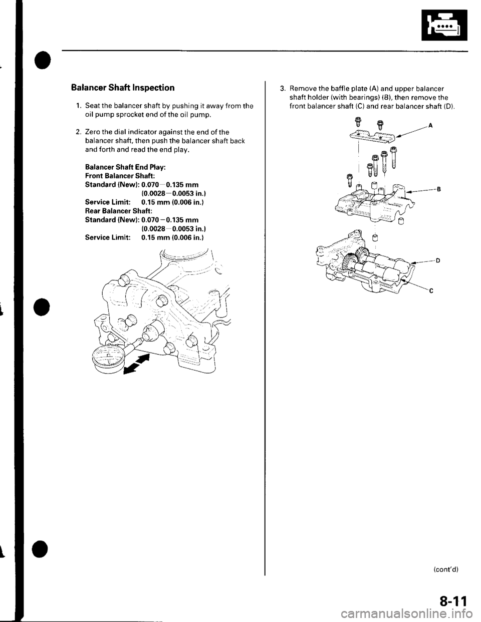
Seat the balancer shaft by pushing it away from the
oil pump sprocket end ofthe oil pump.
Zero the dial indicator against the end of the
balancer shaft, then push the balancer shaft back
and forth and read the end olav.
Balancer Shaft End Play:
Fronl Balancer Shaft:
Standard {Newl: 0.070 0.135 mm
{0.0028 0.0053 in.}
Service Limit: 0.15 mm (0.006 in.)
Rear Balancer Shaft:
Standard {New): 0.070-0.135 mm(0.0028 0.0053 in.l
Service Limit: 0.15 mm (0.006 in.)
2.
3. Remove the baffle plate (A) and upper balancer
shaft holder {with bearings) (B), then remove the
front balancer shaft (C) and rear balancer shaft (D).
9H.A''/.r L=] j/
R
Rfl|]
3I] UUr Be
+-
(cont'd)
8-11
Page 178 of 1139
Engine Lubrication
Oil Pump Overhaul (cont'dl
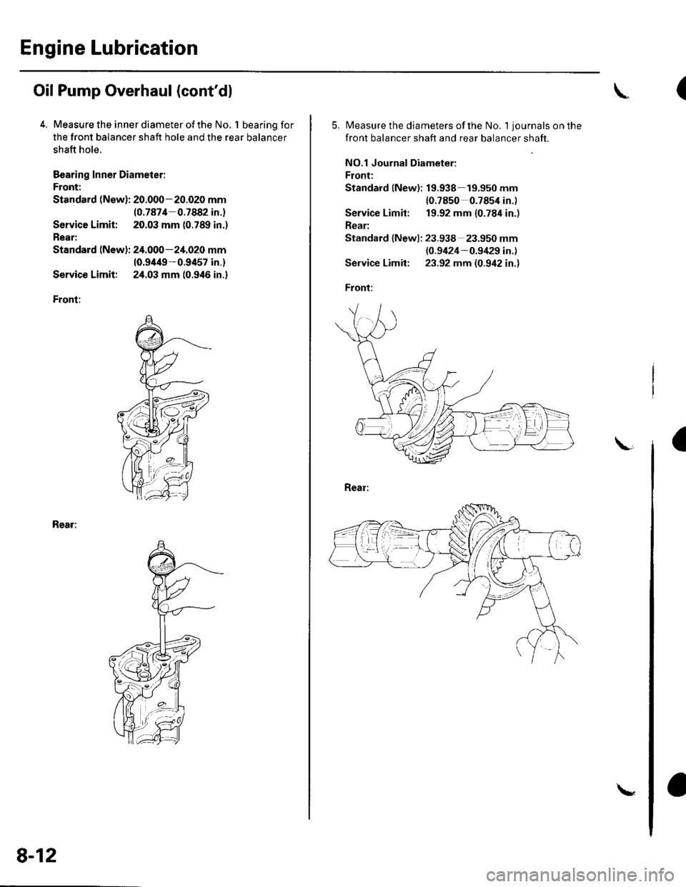
4. Measure the inner diameter of the No. 1 bearing for
the front balancer shaft hole and the rear balancer
shaft hole.
Bearing Inner Diameier:
Front:
Standard (New): 20.000-20.020 mm(0.7874 0.7882 in.)
Service Limit; 20.03 mm (0.789 in.)
Rear:
Standard (New): 24.000-24.020 mm
10.9/t49-0.9457 in.)
Service Limit: 24.03 mm (0.946 in.)
Front:
Rear:
8-12
\
(
5.Measure the diameters of the No. 1 journals on the
front balancer shaft and rear balancer shaft.
NO.1 Journal Diameter:
Front:
Standard lNew): 19.938 19.950 mm(0.7850 0.7854 in.)
Service Limit: 19.92 mm {0.784 in.)
Rear:
Standard lNewl: 23.938 23.950 mm
{0.9424-0.9/129 in.)
Service Limit: 23.92 mm (0.942 in.)
Front:
a
Page 179 of 1139
8.
9.
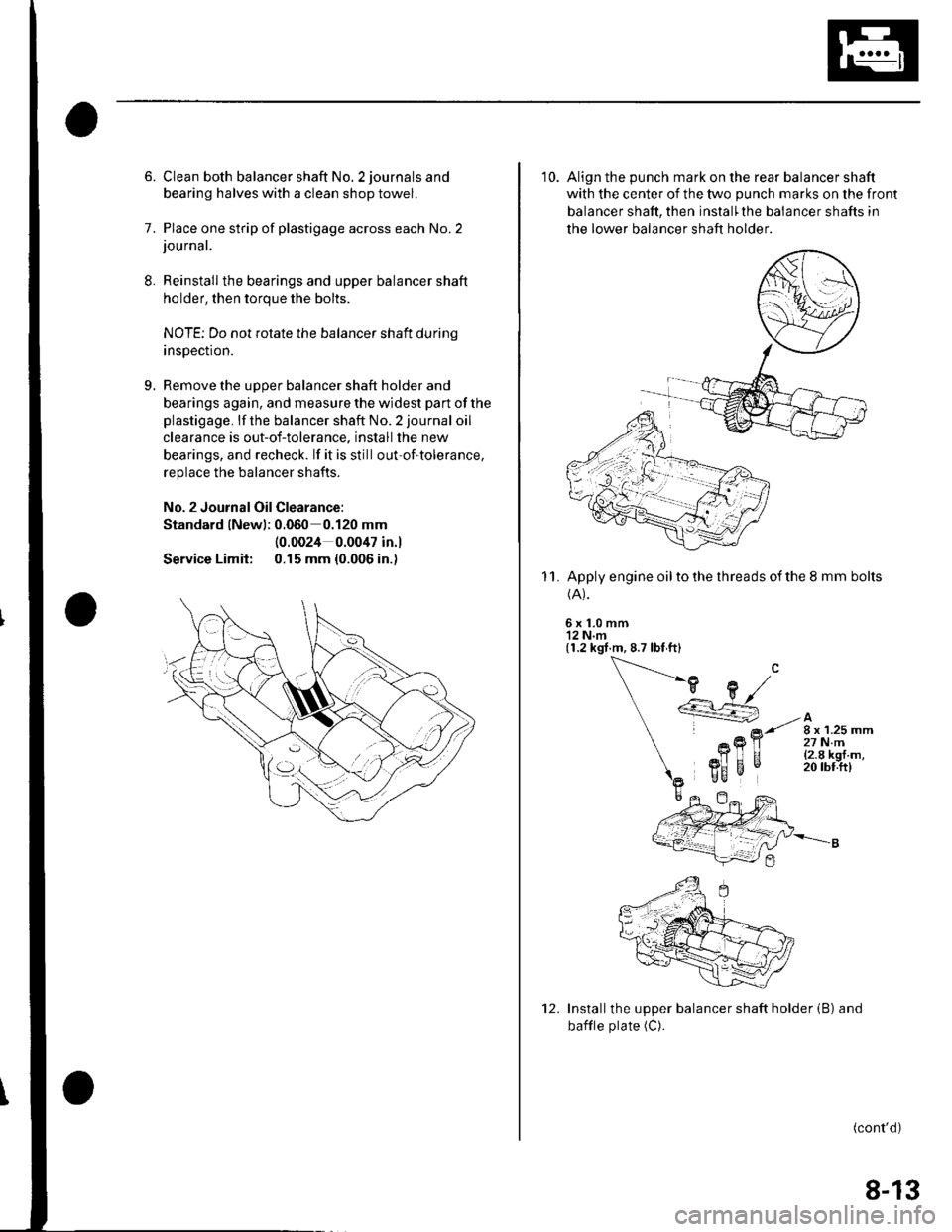
6. Clean both balancer shaft No. 2 journals and
bearing halves with a clean shop towel.
7. Place one strip of plastigage across each No.2journal.
Reinstall the bearings and upper balancer shaft
holder, then torque the bolts.
NOTE; Do not rotate the balancer shaft durinq
insDection.
Remove the uooer balancer shaft holder and
bearings again, and measure the widest part of the
plastigage. lf the balancer shaft No. 2 journal oil
clearance is out-of-tolerance. install the new
bearings, and recheck. lf it is still out-of-tolerance,
replace the balancer shafts.
No. 2 Journal Oil Clearance:
Standard lNewl; 0.060 0.120 mm
Service Limit:
(0.0024 0.0047 in.l
0.15 mm {0.006 in.)
10. Align the punch mark on the rear balancer shaft
with the center of the two punch marks on the front
balancer shaft, then install'the balancer shafts in
the lower balancer shaft holder
Apply engine oil to the threads of the 8 mm bolts(A).
6x1.0mm'12 N.m(1.2 kgt.m, 8.7 lbt ft)
11.
Installthe upper balancer shaft holder (B) and
bafile plate (C).
(cont'd)
12.
8-13
Page 180 of 1139
Engine Lubrication
Oil Pump Overhaul (cont'd)
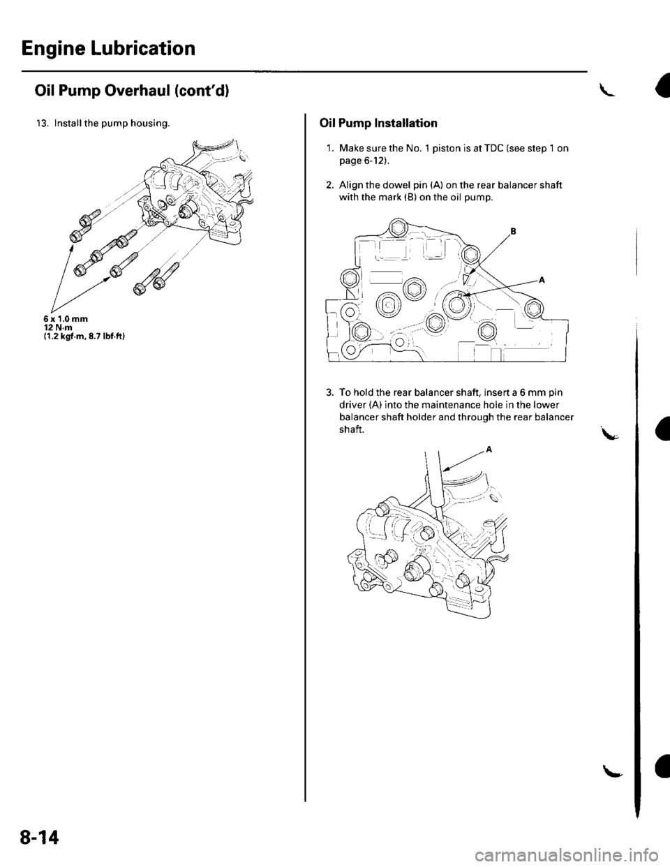
13. lnstallthe pump housing.
6x1,0mm12 N.m(1.2 kgt.m,8.7 lbf.ft)
8-14
!
Oil Pump Installation
1. Make sure the No. 1 piston is at TDC (see step 1 on
page 6-12).
2. Align the dowel pin{A} on the rear balancer shaft
with the mark (B) on the oil pump.
To hold the rear balancer shaft, insert a 6 mm pin
driver {A) into the maintenance hole in the lower
balancer shaft holder and through the rear balancer
shaft.\,-
9%ttrc
+:.:4.4 / t \
o/.-lY\
:aa:'
-rr
dv
f,o-;
Trending: Rear suspension, Valve adjustment, oil change, air suspension, idle control, Filler, low beam
