HONDA CIVIC 2003 7.G Workshop Manual
Manufacturer: HONDA, Model Year: 2003, Model line: CIVIC, Model: HONDA CIVIC 2003 7.GPages: 1139, PDF Size: 28.19 MB
Page 211 of 1139
Fuel and Emissions Systems
General Troubleshooting Information (cont'dl
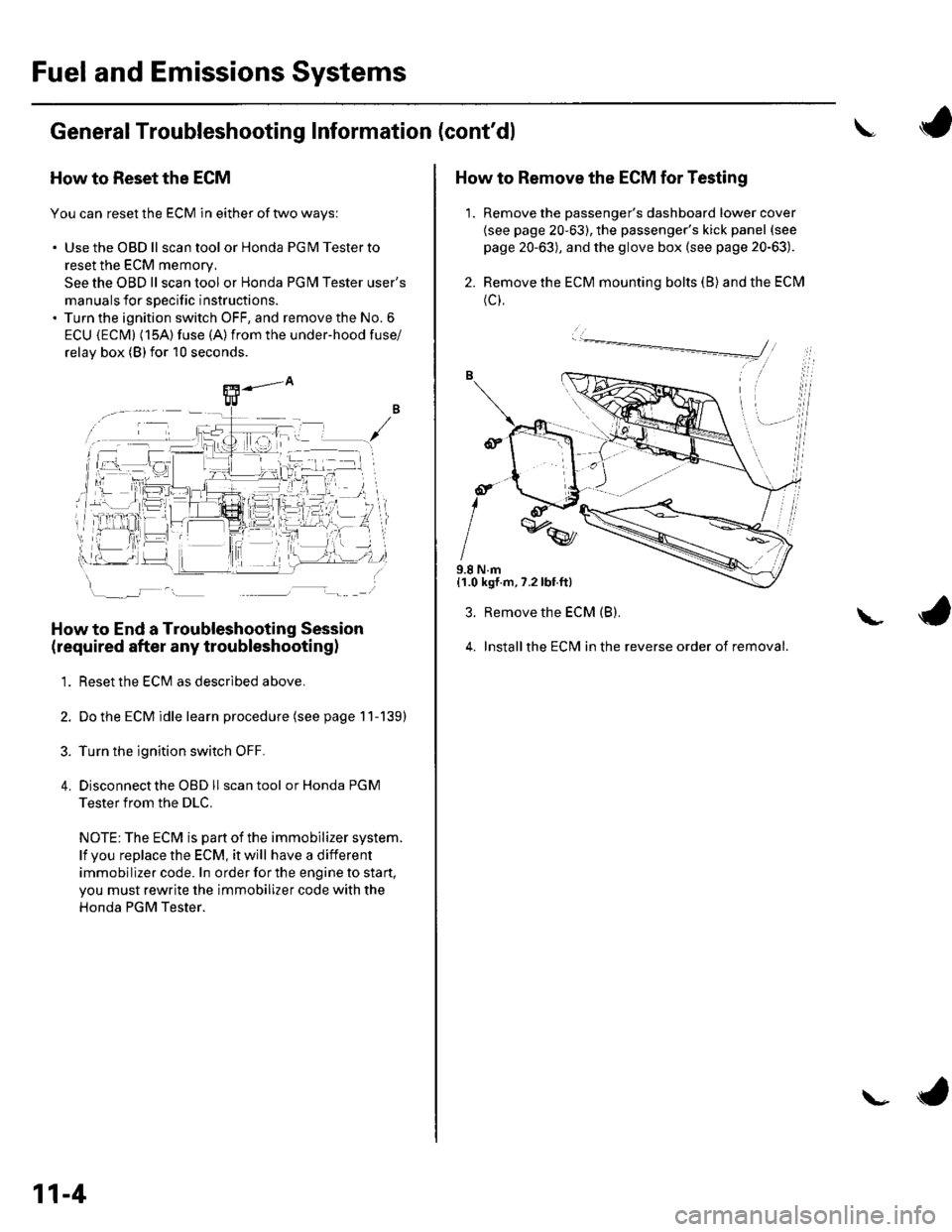
How to Reset the ECM
You can reset the ECM in either of two ways:
. Use the OBD ll scantool or Honda PGMTesterto
reset the ECM memory.
See the OBD ll scan tool or Honda PGI\4 Tester user's
manuals for specific instructions.' Turn the ignition switch OFF, and remove the No. 6
ECU {ECM} (15A) fuse (A)from the under-hood fuse/
relav box (Blfor 10 seconds.
How to End a Troubleshooting Session
(required after any troubleshootingl
1. Reset the ECM as described above.
2. Do the ECM idle learn procedure (see page 11-139)
3. Turn the ignition switch OFF.
4. Disconnectthe OBD ll scan tool or Honda PGM
Tester from the DLC.
NOTE: The ECM is part of the immobilizer system.
lf vou replace the ECM, it will have a different
immobilizer code. In order for the engine to start,
you must rewrite the immobilizer code with the
Honda PGM Tester.
11-4
\- ta
J
How to Remove the ECM for Testing
1. Remove the passenger's dashboard lower cover
{see page 20-63), the passenger's kick panel (see
page 20-63), and the glove box (see page 20-63).
2. Remove the ECM mounting bolts (B) and the ECM
(c),
9.8 N.m{1.0 kgf.m,7.2lbt.ft}
3. Remove the ECM (B).
4. Installthe ECM in the reverse order of removal.
L
Page 212 of 1139
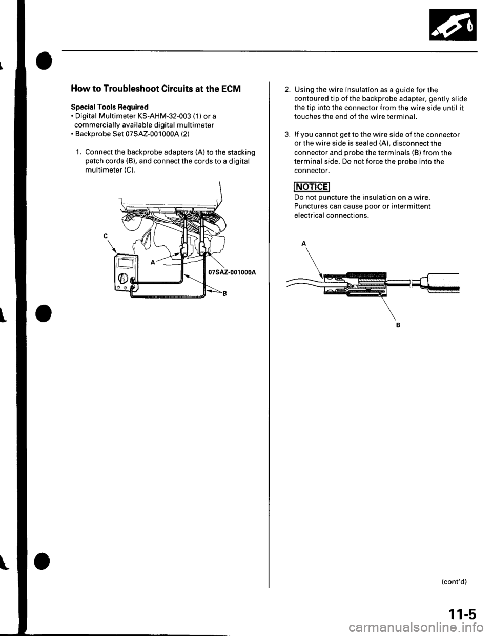
How to Troubleshoot Circuits at the ECM
Special Tools Required. Digital Multimeter KS-AHM-32-003 (1) or a
commercially available digital multimeter. Backprobe Set 07SAZ-0010004 (2)
1. Connect the backprobe adapters (A) to the stacking
patch cords (B), and connect the cords to a digital
multimeter (C).
07sAz-001000A
2. Using the wire insulation as a guide for the
contoured tip ofthe backprobe adapter, gently slide
the tip into the connector from the wire side until it
touches the end of the wire terminal.
3. lf you cannot get to the wire side of the connector
or the wire side is sealed (A), disconnect the
connector and probe the terminals (B) from the
terminal side. Do not force the Drobe into the
connector.
Do not puncture the insulation on a wire.
Punctures can cause Door or intermittent
electrical connections.
(cont'd)
11-5
Page 213 of 1139
Fuel and Emissions Systems
General Troubleshooting Information (cont'd)
ECM Updating and Substitution for Testing
Special Tools Bequired
Honda Interface Module (HlM) EOS05435570
Use this procedure when you have to substitute a
known-good ECM in a troubleshooting procedure.
U pdate the ECM only if the ECN4 does not already have
the latest software loaded,
NOTE;. lMake sure the battery is fully charged before you
update the ECN4.. To prevent ECM damage during the update, do not
turn the ignition switch OFF, and do not use any of
the vehicle's electrical devices (light, horn, radio, etc. ).
How to Update the ECM
1. Turn the ignition switch ON (ll). Do not startthe
eng Ine.
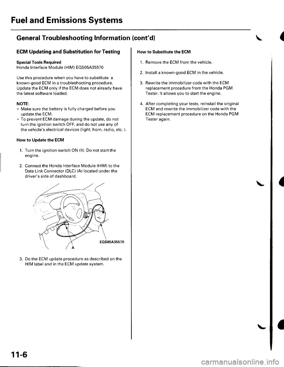
2. Connect the Honda lnterface Module (HlM) to the
Data Link Connector {DLC) (A) located under the
driver's side of dashboard.
EOS05A35570
Do the ECM update procedure as described on the
HlN4 label and in the ECM update system.
11-6
\-
How to Substitute the ECM
'1. Remove the ECM f rom the vehicle.
2. Install a known-good ECM in the vehicle.
3. Rewrite the immobilizer code with the ECM
replacement procedure from the Honda PGM
Tester. lt allows you to start the engine.
4. After completing your tests, reinstall the original
ECM and rewrite the immobilizer code with the
ECM replacement procedure on the Honda PGM
Tester again.
L
(
I
Page 214 of 1139
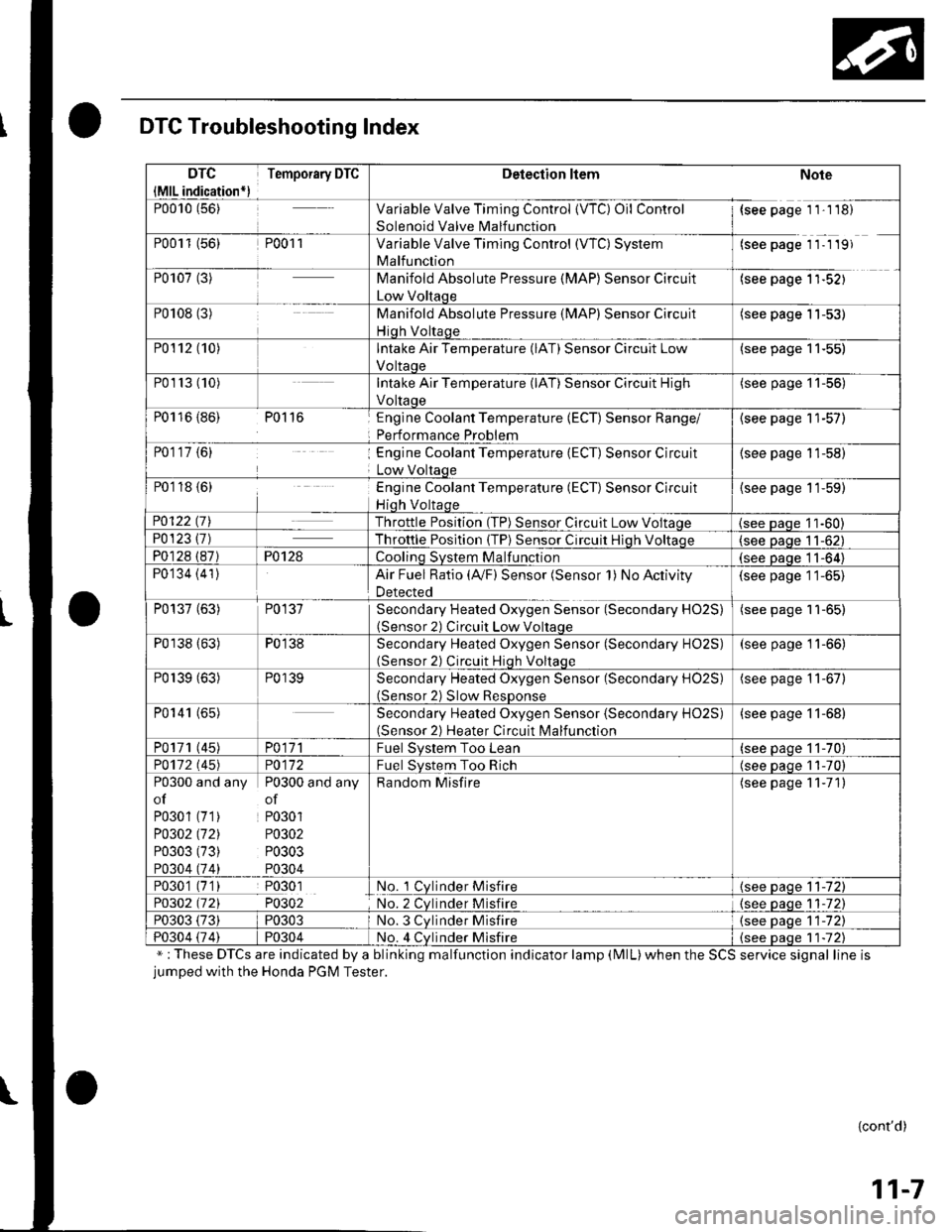
DTC Troubleshooting Index
";These DTCs are indicated by a blinking malfunction indicator lamp (MlL)when the SCS service signal line isjumped with the Honda PGM Tester.
{cont'd)
11-7
DTC
{MlL indication*)
Temporary DTCDetection ltemNote
P0010 (56)Variable Valve Timing Control {VTC) Oil Control
Solenoid Valve Malfunction
{see page 1 1'1 18)
P0011 (56)P001 1Variable Valve Timing Control (WC) System
Malfunction
(see page 11- 1 19)
P0107 (3)Manifold Absolute Pressure (MAP) Sensor Circuit
Low Voltaqe
(see page 1'l-521
P0108 (3)Manifold Absolute Pressure (MAP) Sensor Circuit
Hiqh Voltaqe
(see page 11-53)
P0112 (10)Intake Air Temperature (lAT) Sensor Circuit Low
Voltaoe
(see page 11-55)
P01r3 (10)Intake Air Temperature (lAT) Sensor Circuit High
Voltaoe
(see page '11-56)
P0116 {86) P0116Englne Coolant Temperature (ECT) Sensor Range/
Performance Problem
{see page 11-57)
P0117 {6)Engine Coolant Temperature (ECT) Sensor Circuit
Low Voltaqe
(see page 11-58)
P0118 {6)Engine Coolant Temperature (ECT) Sensor Circuit
Hiqh Voltaqe
{see page 11-59)
P0122 t7\Throttle Position (TP) Sensor Circuit Low Voltaqe(see Daqe 11-60)P0123 {7)Throttle Posltion (TP) Sensor Circuit Hiqh Voltaoe(see paqe 11-62)
P0128 (87)P0128Coolinq SVStem Malfunction(see Daqe 11-64)
P0134 (41)Air Fuel Ratio (Ay'F) Sensor (Sensor 1) No Activity
Detected
(see page 11-65)
P0137 (63)P0137Secondary Heated Oxygen Sensor (Secondary HO2S)(Sensor 2) Circuit Low Voltaqe
(see page 11-65)
P0138 (63)P0138Secondary Heated Oxygen Sensor (Secondary HO2S)(Sensor 2) Circuit Hiqh Voltaqe
(see page 11-66)
P0139 (63)P0139Secondary Heated Oxygen Sensor (Secondary H02S)(Sensor 2) Slow ResDonse
(see page 11-67)
P0141 (65)Secondary Heated Oxygen Sensor (Secondary H02S)(Sensor 2) Heater Circuit Malfunction
(see page 11-68)
P0171 (45)PO\11Fuel Svstem Too Lean(see paqe 11-70)
PO112 l'45)PO\l2Fuel System Too Rich(see oaoe 11-70)
P0300 and any P0300 and any
of of
P0301 (71) P0301
PO302 (721 P0302
P0303 (73) P0303
P0304 (74) P0304
Random Misfire(see page 11-71)
P0301 (7'1) P0301No. 1 Cylnder Misfire{see page 11-72)
P0302 (721 P0302No. 2 Cvlnder Misfire{see paqe 1 1-72)
P0303 (73)P0303No. 3 Cvlnder Misfire(see oaqe 11-72)
P0304 {74)P0304No. 4 Cvlnder Misfire{see Daqe 1 1-72)
Page 215 of 1139
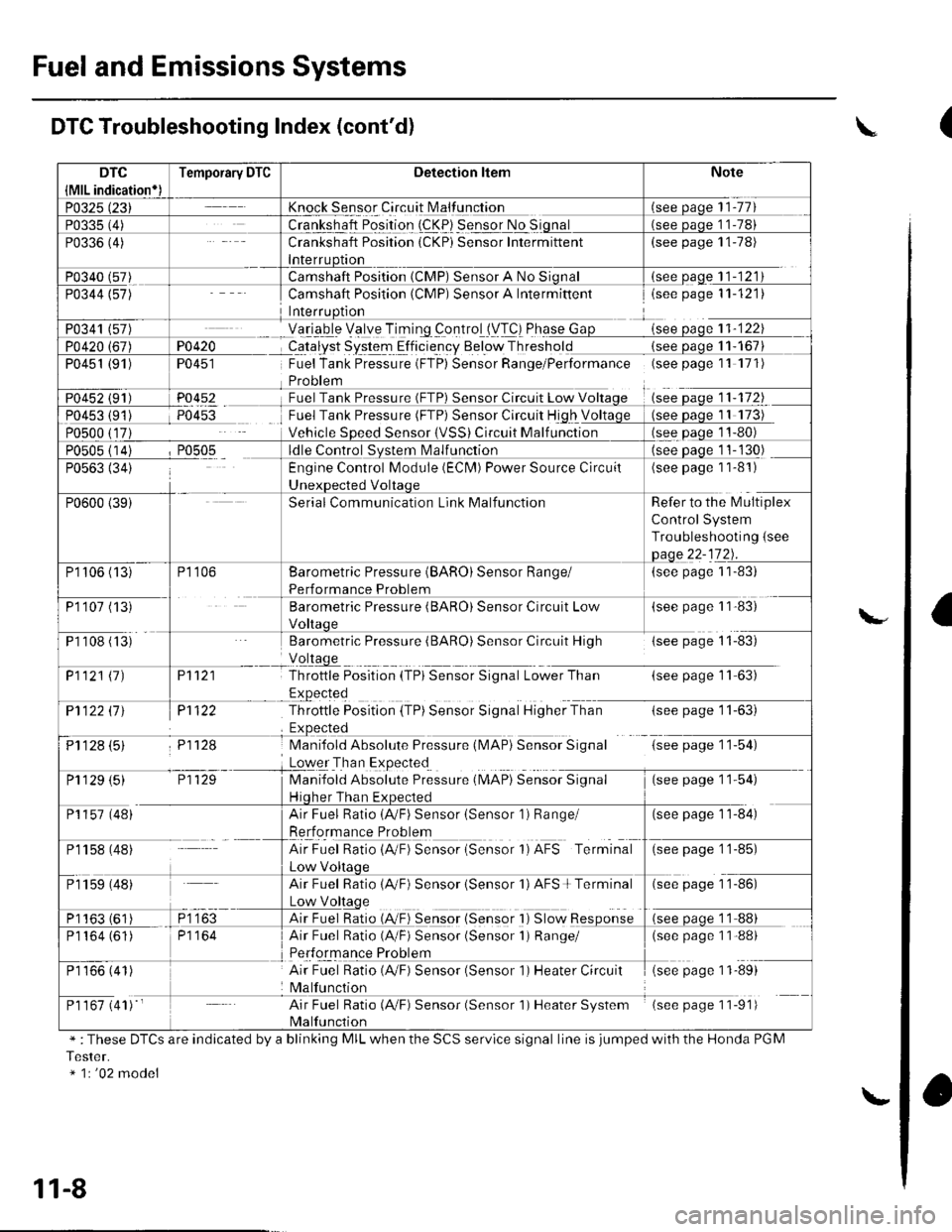
Fuel and Emissions Systems
Knock Sensor Circuit N4alfunction
Crankshaft Position (CKP) Sensor Intermittent(see page 11-78)
(see oaqe 11-121
PO4i{�
TU45I
P0452
Camshaft Position (CMP) Sensor A Intermiftentisee page 11-121)
Yetrgb-le Velye TiTing _controlll/T!) Phqse Gsee oaoe 11-122
CqJalyst System Elficie-ncy Below Thresholdsee oaqe 1 1- 167
Fuel Tank Pressure (FTP) Sensor Range/Performance (seepagell 171)
Sensor Circuit Low V11-172
Fuel Tank Pressure (FTP) Sensor Circuit High V
Vehicle SDeed SensorCircuit Malf unction
Camshaft Position (CMP) Sensor A No
P0451 (91)
see Daqe 11-130)
(see page 1 1-81)
Refer to the l\4ultiplex
Control System
Troubleshooting {see
(see page 1 1-83)
(see paSe 1 1'83)
Barometric Pressure (BARO) Sensor Circuit High{see page 11-83)
P't 121
Pl122
P11f,.8
Throttle Position {TPi Sensor Signal Lower Than(see page 11-63)
-tsee page I r-oJ,
G;tp"s" 1 154)
(*" paSe 1 154)
P1122 ll J
ij1128 (5)
Throttle Position (TP) Sensor Signal Higher Than
Mani{old Absolute Pressure (l\,4AP} Sensor Signal
Loqer Tha n Expected
Manifold Absolute Preisure (MAP) SeiiioiSgnul
Hiqher Than Ex(see page 11-84)
Engine Control Module (ECN4) Power Source Circuil
Serial Communication Link Malfunction
P1106 (13)
P110? (13
P1 108 (ts'
Barometric Pressure (BARO) Sensor Range/
Performance Problem
Barometric Pressure (BARO) Sensor Circuit Low
P1121 11)
P1 129 (5)
P1157 (48)
Pr 158 (48)
Air Fuel Ratio (AVF) Sensor (Sensor 1) Range/
Rerformance Problem
AirFuel Ratio{A"F) Sensor {Sensor 1)AFS Terminal(see page 1 1-85)
Air Fuel Ratio 1AVF) Sensor isensor 'l) AFS + Terminal(see page 1 1-86)
Air Fuel Ratio {A,/F) Sensor {Sensor I ) Slow Response
Air Fuel Ratio (A/F) Sensor (Sensor 1) Range/(see page 1 1-88)
Air Fuel Ratio (4,/F) Sensor (Sensor 1) Heater Circuit
Malfunction
(see page 11-89)
Air Fuel Ratio (A,/F) Sensor (Sensor 1) Heater System
Malfunction
(see page 11-91)
P1 159 (48)
P1163 (61
P1164 (61)
P1 166 (41)
P1 167 (41) '
DTC Troubleshooting Index (cont'd)
" :These DTCS are indicated by a blinking MIL when the SCS servlce signal line is jumped with the Honda PGM
Tester.* 1r '02 model
\
l\."
11-8
\.
(
a
Page 216 of 1139
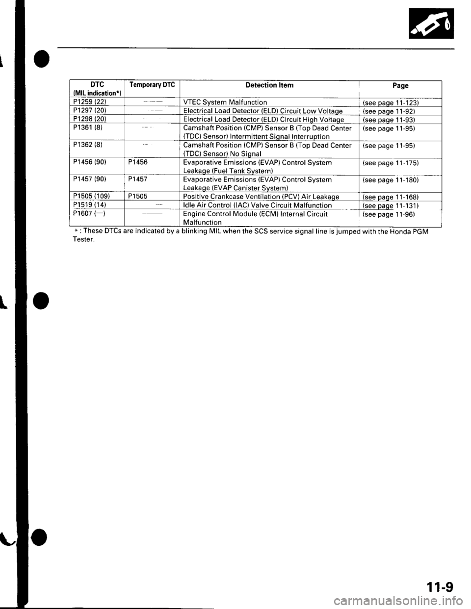
DTC
{MlL indication*l
Temporary DTCDetection ltemPage
P1259 t22JVTEC System l\4alfunction(see Daqe 11-123)P1291 t20\Electrical Load Detector (ELD) Circuit Low Voltaqe(see Daqe l1-92)P1298 (20)Electrical Load Detector (ELD) Circuit Hiqh Voltaqe(see oaoe 11-93)P1361 (8)Camshaft Position (CMP) Sensor B (Top Dead Center(TDC) Sensor) Intermittent Sional InterruDtion
(see page 11-95)
P1362 (8)Camshaft Position (CMP) Sensor B (Top Dead Center(TDC) Sensor) No Siqnal
(see page 11-95)
P'r456 (90)P1456Evaporative Emissions (EVAP) Control System
Leakaqe (Fuel Tank Svstem)
(see page 11-175)
P14s7 (90)P1457Evaporative Emissions (EVAP) Control System
Leakaqe (EVAP Canister Svstem)
(see page 1'l-180)
P1505 (109)P1505Positive Crankcase Ventilation (PCV) Air Leakaqe(see oaqe 11-1681
P1519 (14)ldle Air Control (lAC) Valve Circuit Malfunction{see paqe 11-131)P1607 ( )Engine Control Module (ECM) Internal Circuit
Malfunction
(see page 1 1-96)
" : These DTCS are indicated by a blinking MIL when the SCS service signal line is jumped with the Honda PGM
Tester.
11-9
Page 217 of 1139
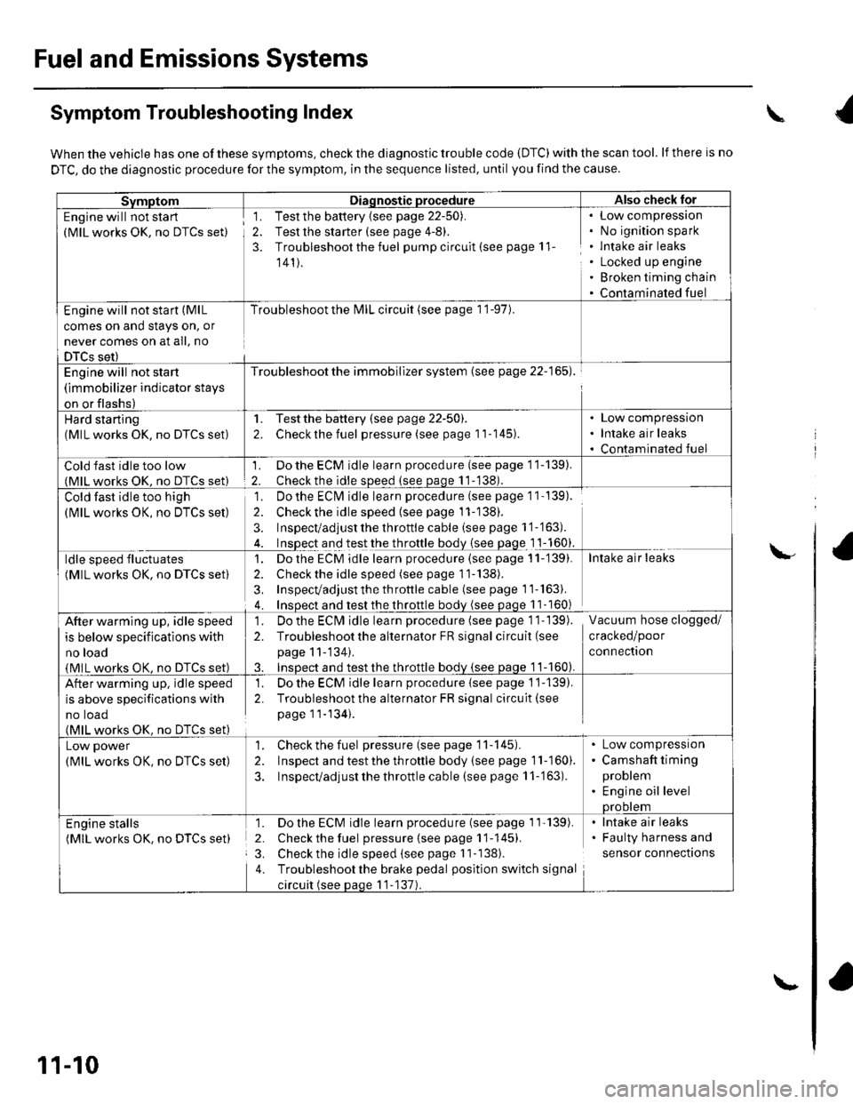
Fuel and Emissions Systems
Symptom Troubleshooting Index
When the vehicle has one of these symptoms, check the diagnostic trouble code (DTC) with the scan tool. lf there is no
DTC, do the diagnostic procedure for the symptom, in the sequence listed, until you find the cause.
SvmotomDiaqnostic procedureAlso check lor
Engine will not sta rt
(MlL works OK, no DTCS set)
1. Test the battery {see page 22-50).
2. Test the starter (see page 4-8).
3. Troubleshoot the fuel pump circult (see page 11
141).
Low compressron
No ignition spark
lntake air leaks
Locked up engine
Broken timing chain
Contaminated fuel
Engine will not start (MlL
comes on and stays on, or
never comes on at all, no
DTCS set)
Troubleshoot the l\4lL circuit (see page 1 '1-97).
Engine will not start
(immobilizer indicator stays
on or flashs)
Troubleshoot the immobilizer system (see page 22-165).
Hard starting(MlL works OK, no DTCS set)
1. Testthe battery (see page 22-50).
2. Checkthe fuel pressure (see page 11-145).
Low compression
Intake air leaks
Contaminated fuel
Cold fast idle too low(MlL works OK. no DTCS set)
1. Do the ECM idle learn procedure (see page 11-139).
2. Checkthe idle sDeed (see paqe 11-138).
Cold fast idle too high
(MlL works OK, no DTCS set)
Do the ECI\4 idle learn procedure (see page 1 1- 139).
Checkthe idle speed {see page 11-138).
Inspect/adjust the throttle cable (see page 1 '1-'163).
Inspect and test the throttle body {see page 1 1-160}.
']�
2.
3.
ldle speed fluctuates
(MlL works OK, no DTCS set)
1. Dothe ECM idle learn procedure (see page 11-'139).
2. Check the idle speed (see page 11-138).
3, Inspecvadjust th e throttle cable (see page 11''163).
4. Insoect and test the throttle bodv (see paqe 11- 160)
Intake air leaks
After warming up, idle speed
is below specifications with
no load
{MlL works OK, no DTCS set)
1. Do the ECIVI idle learn procedure (see page 1 1- 139).
2. Troubleshootthe alternator FR signal circuit (see
page 11-'134).
3. InsDect and test the throttle bodv {see paqe 1 1-160).
Vacuum hose clogged/
cracked/poor
connectron
After warming up, idle speed
is above specifications with
no toao(MlL works OK. no DTCS set)
1. Do the ECM idle learn procedure {see page 1'j-139).
2. Troubleshoot the alternator FR signal circuit(see
page 11-134).
Low power
(MlL works OK, no DTCS set)
1. Check the fuel pressure(seepagell-145).
2. Inspect and test the th roftle body (see page 11-160).
3. Inspecvadjust the throttle cable (see page 11-'163).
Low compressron
Camshaft timing
problem
Engine oil levelprootem
Engine stalls(MlL works OK. no DTCS set)
1. Do the ECM idle learn procedure (see page 1'l'139).
2. Check the fuel pressure{seepagell-145).
3. Check the idle speed (see page I 1-138).
4. Troubleshootthe brake pedal position switch signal
circuit (see paqe 11-137).
lntake air leaks
Faulty harness and
sensor connections
\
\-
11-10
\-
Page 218 of 1139
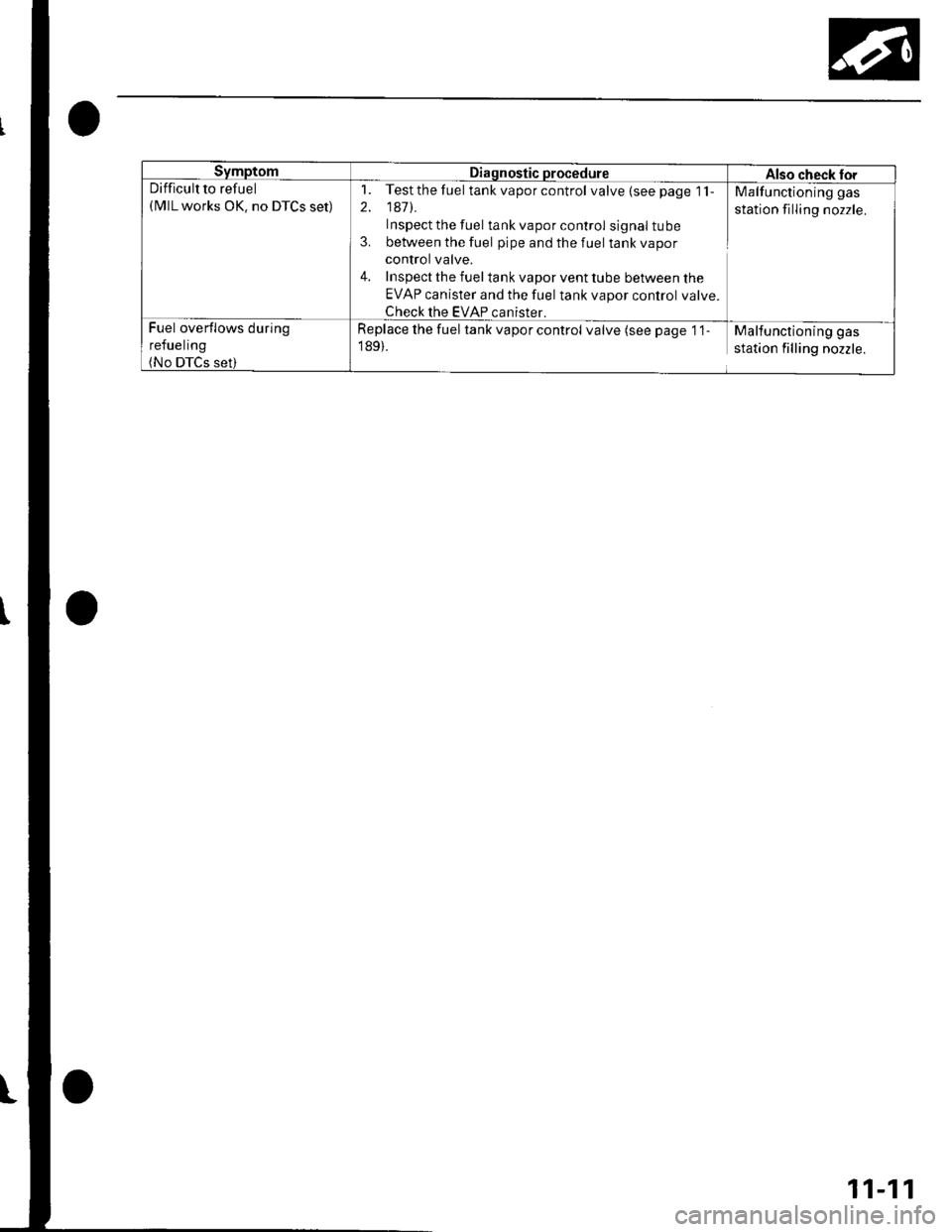
SymptomDiagnostic procedureAlso check torDifficult to refuel(MlL works OK. no DTCS set)
1. Testthefuel tank vapor control valve{seepage 1'l-
2. 1471.
Inspect the fuel tank vapor control signal tube
3. between the fuel pipe and the fuel tank vapor
control valve.
4. Inspect the fuel tank vapor vent tube between the
EVAP canister and the fuel tank vapor control valve.
Check the EVAP canister.
Malfunctioning gas
station filling nozzle.
Fuel overflows during
refueling(No DTCS set)
Replace the fuel tank vapor control valve (see page '1 1
189).
Malfunctioning gas
station filling nozzle.
11-11
Page 219 of 1139
Fuel and Emissions Systems
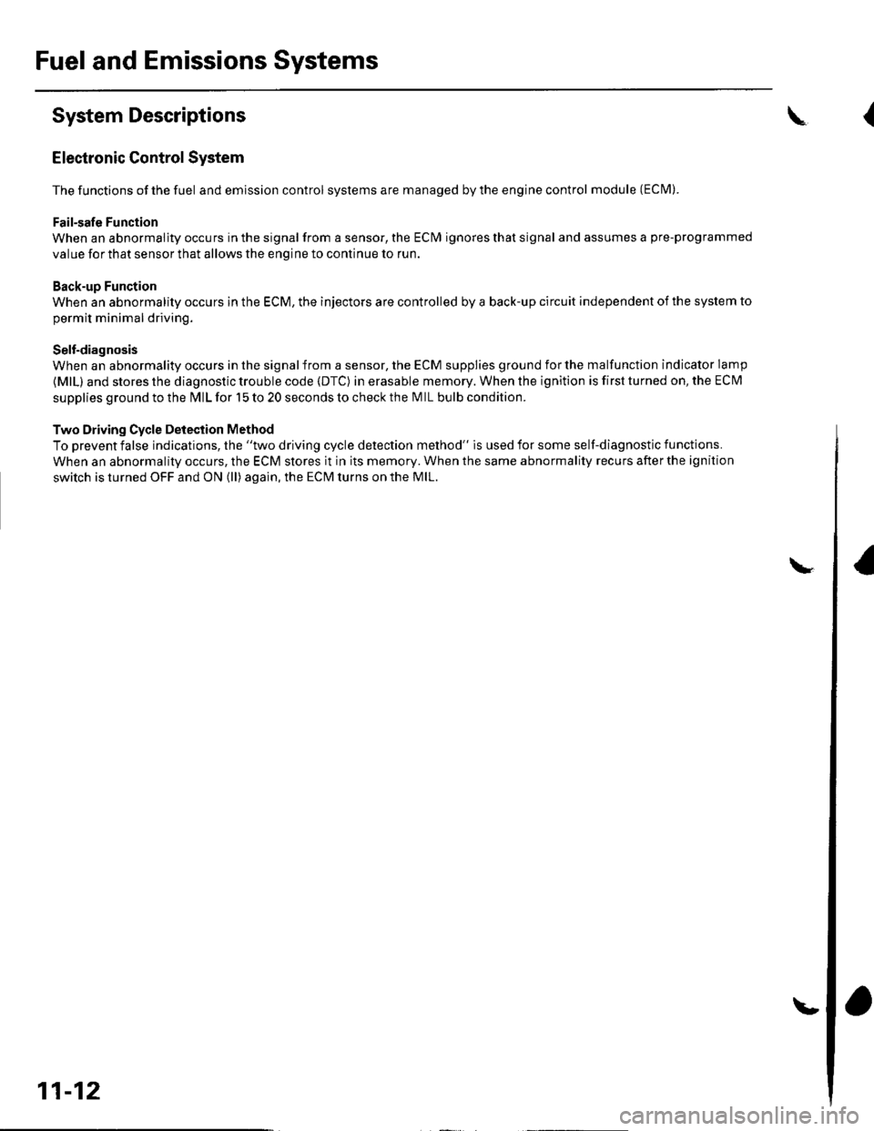
System Descriptions
Electronic Control System
The functions of the fuel and emlssion control systems are managed by the engine control module (ECM).
Fail-safe Function
When an abnormality occurs in the signal from a sensor, the ECI\4 ignores that signal and assumes a pre-programmed
value for that sensor that allows the enqine to continue to run.
Back-up Function
When an abnormality occurs in the ECM, the injectors are controlled by a back-up circuit independent of the system to
permit minimal driving.
Self-diagnosis
When an abnormality occurs in the signal from a sensor, the ECM supplies ground for the malfunction indicator lamp
{MlL) and stores the diagnostic trouble code {DTC) in erasable memory. When the ignition is first turned on, the EClvl
supplies ground to the l\4lL for 15 to 20 seconds to check the M lL bulb condition.
Two Driving Cycle Detection Method
To prevent false indications, the "two driving cycle detection method" is used for some self-diagnostic functions.
When an abnormality occurs, the ECM stores it in its memory. When the same abnormality recurs afterthe ignition
switch is turned OFF and ON (ll) again, the ECM turns on the MlL.
\
11-12
\.
\{
Page 220 of 1139
ECM Data
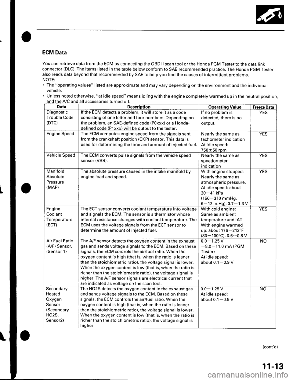
You can retrieve data from the ECI\4 by connecting the OBD ll scan tool or the Honda PGM Tester to the data link
connector (DLC). The items listed in the table below conform to SAE recommended practice. The Honda PGM Tester
also reads data beyond that recommended by SAE to help you find the causes of intermittent problems.
The "operating values" listed are approximate and may vary depending on the environment and the individual
vehicle.
Unless noted otherwise, "at idle speed" means idling with the engine completely warmed up in the neutral position,
and the A,/C and all
Diagnostic
Trouble Code(DTC}
lf the ECM delects a problem, it will store it as a code
consisting of one letter and four numbers. Depending on
the problem, an SAE-defined code (Poxxx) or a Honda,
defined code {P1xxx) will be output to the tester.
The ECI\4 computes engine speed from the signals sent
from the crankshaft position (CKP) sensor. This data is
used for determining the time and amount of injected fuel.
detected, there is no
ourpul.
lf no problem is YES
Nearly the same as
tachometer indication
At idle speed;
The ECM converts pulse signals from the vehicle speed
sensor (VSS).Nearly the same as
speedometer
indication
Manifold
Absolute
Pressure(MAP)
The absolute pressure caused in the intake manifold by
engine load and speed.
With engine stopped: YES
Nearly the same as
almospnenc pressure.
At idle speed: about
20 4'1 kPa(150 310 mmHg,
6- 12 in.Hq).0.7 1.3 V
The ECT sensor converts coolant temperature into voltage
and signals the ECM. The sensor is a thermistor whose
internal resistance changes with coolant tempetature. The
ECM uses the voltage signals from the ECT sensor to
determine the amount of injected fuel.
With cold engine:
Same as ambient
temperature and IAT
With engine warmed
up; about 116 2'12"F
100'c).0.5-0.8 v
Air Fuel Ratio The A,/F sensor detects the oxygen content in the exha ust 0.0 - 1 .25 V(Ay'F) Sensor. gas and sends voltage signals to the Eclvl, Basedonthese 8.0 11.0mA(PGM(Sensor 1) signals, the ECM controls the airlfuel ratio. When the I Tester)
oxygen content is high (that is, when the ratio is leaner At idle speed:
than the stoichiometric ratio), the voltage signal is Iower. about 0.1 0.9 V
When the oxygen content is low (that is, when the ralio is
richer than the stoichiometric ratio). the voltage signal is
higher. The A'lF sensor signals are electrical current that
are indicated as voltaqe on the
The HO2S detects the oxygen content in the exhaust gas
and sends voltage signals to the ECM. Based on these
signals, the ECM controls the airlfuel ratio. When the
oxygen content is high (that is, when the ratio is leaner
than the stoichiometric ratio), the voltage signal is lower.
When the oxygen content is low (that is, when the ratio is
richer than the stoichiometric ratio), the voltage signal is
Secondary
Heated
Oxygen
Sensor(Secondary
H02S,
Sensor2)
0.0 1.25 V NO
At idle speed:
about 0.1 0.9 V
(cont'd)
11-13