Front HONDA CIVIC 2003 7.G Repair Manual
[x] Cancel search | Manufacturer: HONDA, Model Year: 2003, Model line: CIVIC, Model: HONDA CIVIC 2003 7.GPages: 1139, PDF Size: 28.19 MB
Page 565 of 1139
Front Toe Inspection/Adjustment
Use commercially-available computerized four wheel
alignment equipment to measure wheel alignment(caster, camber, toe, and turning angle). Follow the
equipment manufacturer's instructions,
1. Center the steering wheel spokes.
2. Checkthetoe. lf it is not with in the specif ication, go
to step 3.
Front toe-in: 0 t 3 mm {0 t 0.12 in.)
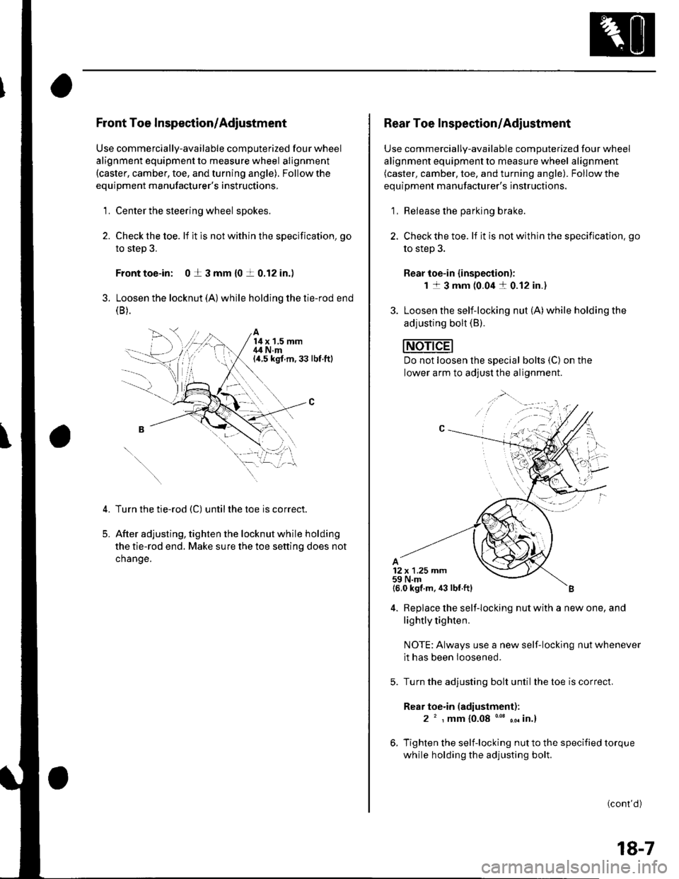
3. Loosen the locknut (A) while holding the tie-rod end(B ).
A14x 1.5 mm,14 N.m(a.5 kgt m,33 lbt.ftl
5.
Turn the tie-rod (C) untilthe toe is correct.
After adjusting, tighten the locknut while holding
the tie-rod end. Make sure the toe setting does not
change.
1,;
Rear Toe Inspection/Adiustment
Use commercially-available computerized four wheel
alignment equipment to measure wheel alignment(caster, camber, toe, and turning angle). Follow the
equipment manufacturer's instructions.
1, Release the parking brake.
2. Checkthe toe. lf it is not within the specification. go
to step 3.
Rear toe-in {inspection):
1 1 3 mm (0.04 a 0.12 in.)
3. Loosen the self-locking nut (A)while holding the
adjusting bolt (B).
Do not loosen lhe special bolts (C) on the
lower arm to adjust the alignment.
4. Replace the self-locking nut with a new one, and
lightly tighten.
NOTE: Always use a new self-locking nut whenever
it has been loosened.
Turn the adjusting bolt until the toe is correct.
Rear toe.in (adiustment):
2 ' , mm {0.08 "' ,. in.}
Tighten the self-locking nut to the specified torque
while holding the adjusting bolt.
(cont'd )
18-7
Page 566 of 1139
Front and Rear Suspension
Wheel Alignment (cont'dl
Turning Angle Inspection
Use commercially-available computerized four wheel
alignment equipment to measure wheel alignment(caster. camber, toe, and turning angle). Followthe
equiDment manufacturer's instructions.
1. Turn the steering wheel fullytotherightandleft
while applying the brake, and check the turning
angles of both front wheels, lf the turning angle is
not within the specification or the inward turning
angles differ between the right and left side, go to
steD 2.
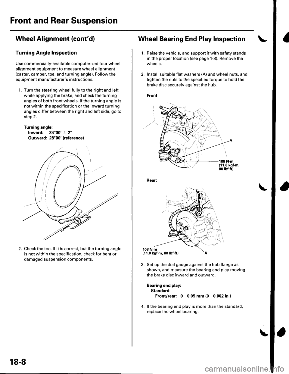
Turning angle:
lnward: 34'00'+ 2'
Outward: 28'00' {reference)
Check the toe. lf it is correct, but the turning angle
is not within the specification, check ior bent or
damaged suspension components,
18-8
Wheel Bearing End Play Inspec'tion
1. Raise lhe vehicle, and support it with safety stands
in the proper location (see page 1-8). Remove the
wheels.
2. Install suita ble f lat washe rs (A) and wheel nuts, and
tighten the nuts to the specified torque to hold the
brake disc securely against the hub.
Front:
108 N.m(11.0 kgf.m,80 rbf.ft)
Rear:
108 N.m
3. Set up the dial gauge against the hub flange as
shown, and measure the bearing end play moving
the brake disc inward and outward.
Bearing end play:
Standard:
Front/rear: 0 0.05 mm {0 0.002 in.}
4. lf the bearing end play is more than the standard,
replace the wheel bearing.
\
(11.0 kgf.m,80 lbf.ft)
Page 567 of 1139
Wheel Runout Inspection
1.Raise the vehicle, and support it with safety stands
in the proper location (see page 1-5,.
Check for a bent or deformed wheel.
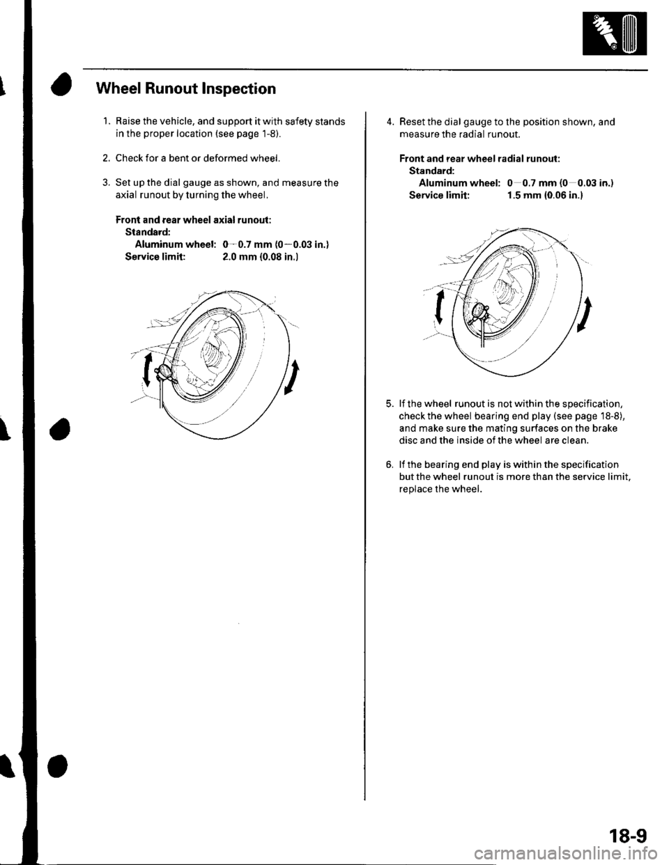
Set up the dial gauge as shown, and measure the
axial runout by turning the wheel.
Front and rear wheel axial runout:
Standard:
Aluminum wheel: 0-0.7 mm (0-0.03 in.)
Service limit: 2.0 mm {0.08 in.l
4. Reset the dial gaugetothe position shown, and
measure the radial runout.
Front and rear wheel radial runout:
Standard:
Aluminum wheel: 0 0.7 mm (0 0.03 io.)
Service limit: 1.5 mm {0.06 in.}
lf the wheel runout is not within the specification,
checkthe wheel bearing end play (see page 18-8),
and make sure the mating surfaces on the brake
disc and the inside of the wheel are clean.
lf the bearing end play is within the specification
but the wheel runout is more than the service limit.
replace the wheel.
18-9
Page 568 of 1139
Front and Rear Suspension
BallJoint Removal
Special Tools Required
Ball ioint remover.2S mm 07MAC-SL00200
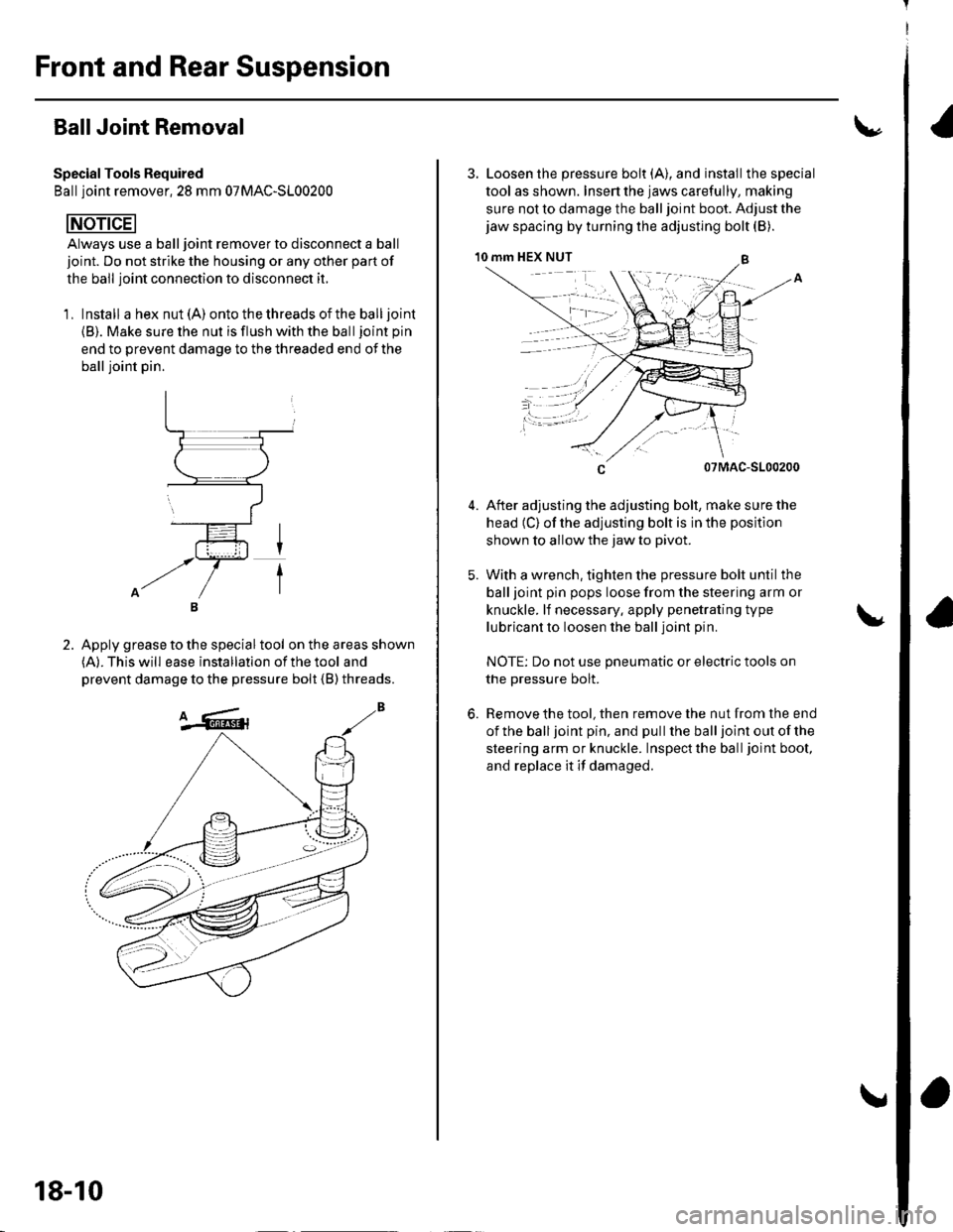
Always use a ball joint remover to disconnect a ball
joint. Do not strike the housing or any other part of
the ball joint connection to disconnect it.
'1, Install a hex nut (A) ontothethreadsoftheballjoint
{B). Make sure the nut is flush with the balljoint pin
end to prevent damage to the threaded end of the
ball ioint oin.
Apply grease to the special tool on the areas shown(A). This will ease installation of the tool and
prevent damage to the pressure bolt {B) threads.
2.
18-10
3. Loosen the pressure bolt (A), and installthe special
tool as shown. Insen the jaws carefully, making
sure not to damage the ball joint boot. Adjust the
jaw spacing by turning the adjusting bolt (B).
10 mm HEX NUT
5.
07MAC-S100200
After adjusting the adjusting bolt, make sure the
head (C) of the adjusting bolt is in the position
shown to allow the jaw to pivot.
With a wrench, tighten the pressure bolt until the
ball ioint pin pops loose from the steering arm or
knuckle. lf necessary. apply penetrating type
lubricant to loosen the ball joint pin
NOTE: Do not use pneumatic or electric tools on
the pressure bolt.
Remove the tool, then remove the nut from the end
ofthe balljoint pin, and pullthe balljoint out ofthe
steering arm or knuckle. Inspectthe balljoint boot,
and replace it if damaged.
6.
Page 569 of 1139
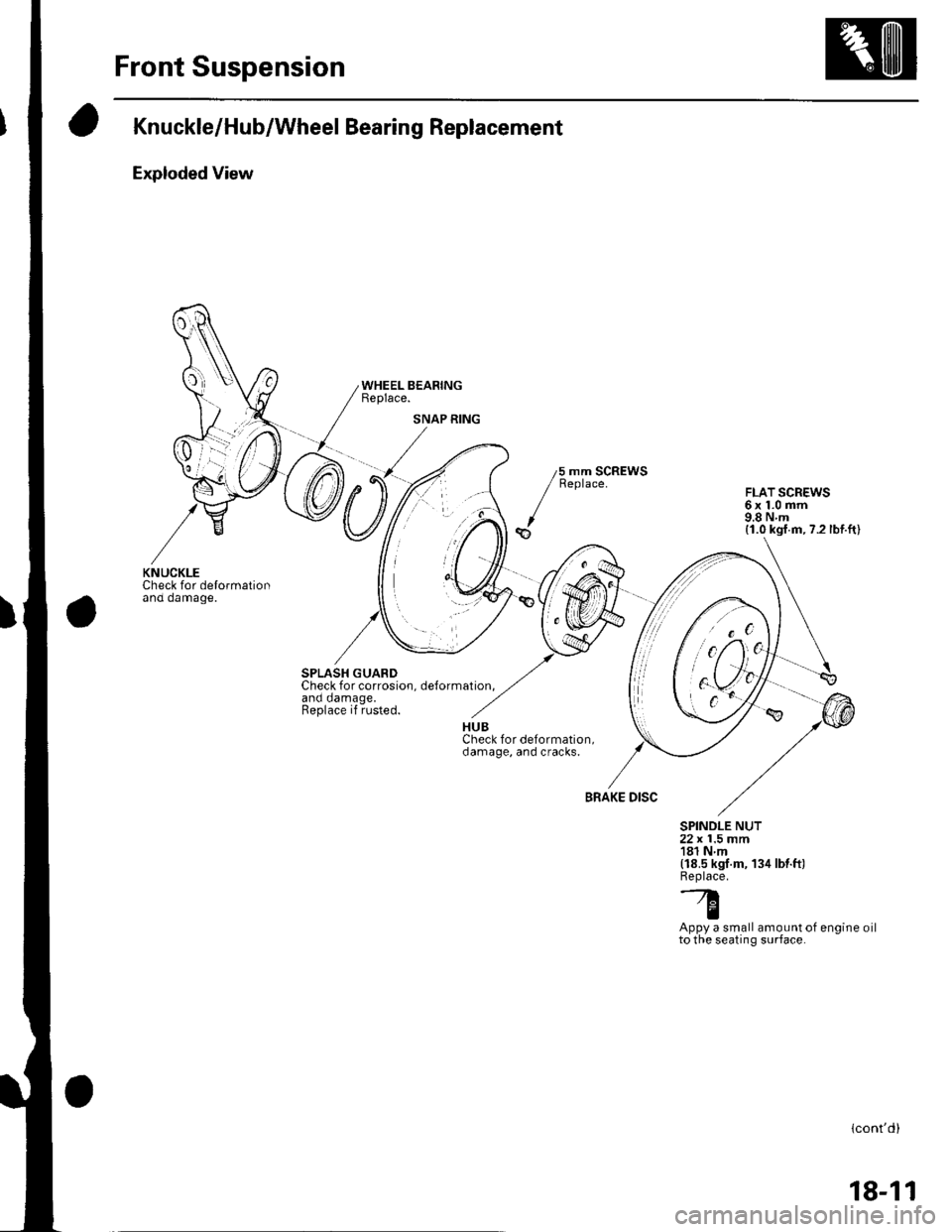
Front Suspension
Knuckle/Hub/Wheel Bearing Replacement
Exploded View
Check for delormationano oamage.
SPLASH GUARDCheck for corrosion. delormation.and damage.Replace if rusted.
WHEEL BEARINGReplace.
5 mm SCREWSReplace.FLAT SCREWS6x1.0mm9.8Nm(1.0 kgf.m,7.2 lbf.ft)
BRAKE DISC
SPINDLE NUT22 x 1.5 mm181 Nm(18.5 kgf.m, 134 lbt.ft)Replace.'--7.l'tq
IAppy a small amount of engine oilto the seating surface.
lcont'd)
SNAP RING
KNUCKLE
18-11
Page 570 of 1139
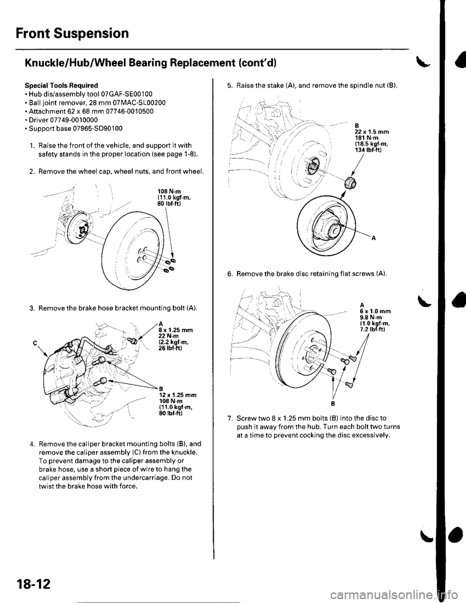
Front Suspension
Knuckle/Hub/Wheel Bearing Replacement {cont'dl
Special Tools Required. Hub dis/assembly tool 07GAF-SE00100. Balljoint remover,2S mm 0TlvlAC-S100200. Attachment 62 x 68 mm 07746-0010500. Driver 07749-0010000. SuDDort base 07965-5D90'100
1. Raise the front of the vehicle, and support it with
safety stands in the proper location (see page 1-8).
2. Remove the wheel cap, wheel nuts, and front wheel.
3. Remove the brake hose bracket mounting bolt (A).
108 N.m(11.0 kgf m,80 rbf.ftl
A8 x 1.25 mm22N.m12.2ksl.m,26 tbf.ftl
B12 x 1.25 mm108 N.m{11.0 kgf.m,80 rbf.ftl
4.Remove the caliper bracket mounting bolts (B), and
remove the caliper assembly (C) from the knuckle.
To prevent damage to the caliper assembly or
brake hose, use a short piece of wire to hang the
caliper assembly from the undercarriage. Do not
twist the brake hose with force.
18-12
5. Raise the stake (A), and remove the spindle nut (B).
-B
' 22x1.5mm, 181 N.m('18.s kgf.m,134 tbt.ft)
6. Remove the brake disc retaining flat screws (A).
A6x1.0mm9.8 N.m{1.0 kgt.m,7.2 tbl.ttl
7. Screw two 8 x 1.25 mm bolts (B) into the disc to
oush it awav from the hub. Turn each bolt two turns
at a time to prevent cocking the disc excessively,
\
\
Page 572 of 1139
Front Suspension
Knuckle/Hub/Wheel Bearing Replacement (cont'd)
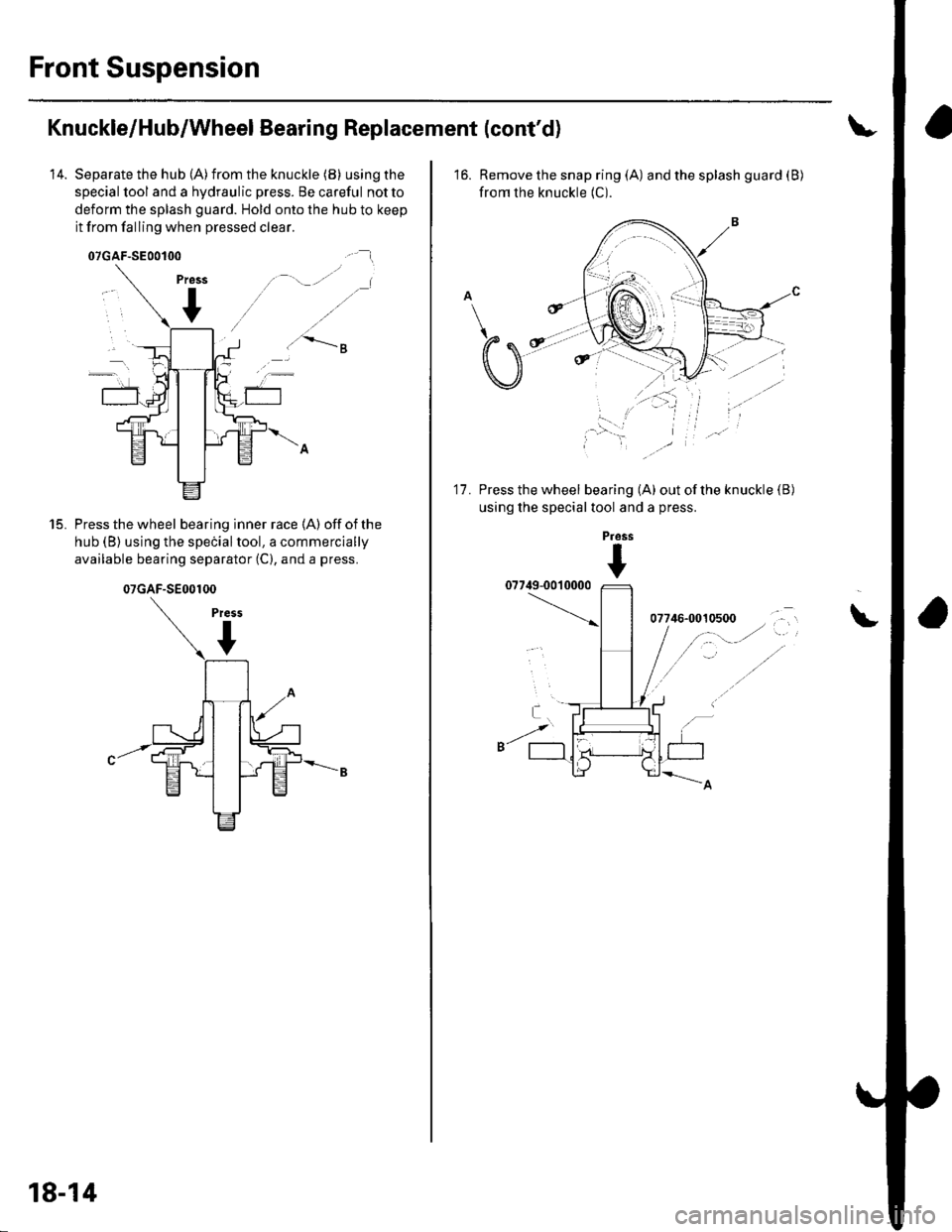
14. Separate the hub (A)from the knuckle (B) using the
special tool and a hydraulic press. Be careful notto
deform the splash guard. Hold onto the hub to keep
it from falling when pressed clear.
./ .-''- .|
a'\s
Press the wheel bearing inner race (A) off of the
hub (B) using the speiialtool, a commercially
available bearing separator (C), and a press.
15.
07GAF-SE00100
Press
07GAF-SE00100
18-14
16. Remove the snap ring (A) and the splash guard (B)
from the knuckle (C).
Press the wheel bearing (A) out of the knuckle (B
using the special tool and a press.
11.
Pross
+
\
Page 573 of 1139
18.
19.
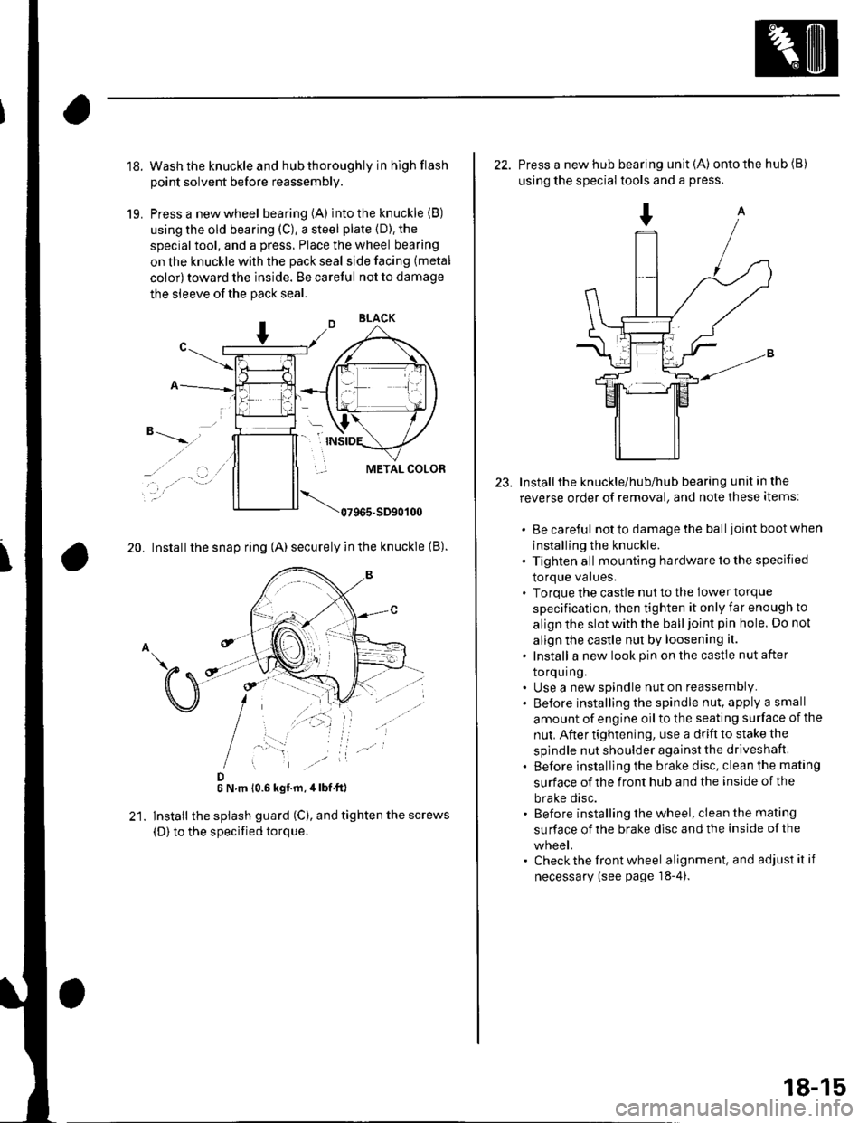
Wash the knuckle and hub thoroughly in hlgh flash
point solvent before reassembly.
Press a new wheel bearing (A) into the knuckle (B)
using the old bearing (C), a steel plate {D). the
special tool, and a press. Place the wheel bearing
on the knuckle with the pack seal side facing (metal
color) toward the inside. Be careful not to damage
the sleeve of the pack seal.
"-t-_"*,,''
_, .' . . a-�.) ../
..-.
20. Install the snap ring (A) securely in the knuckle (B).
D6 N.m 10.6 kgf.m,4lbf ft)
lnstall the splash guard (C), and tighten the screws
(D) to the specified torque.
23.
22. Press a new hub bearing unit {A) ontothehub(B)
using the special tools and a press.
Installthe knuckle/hub/hub bearing unit in the
reverse order of removal, and note these items:
. Be careful notto damagethe balljoint bootwhen
installing the knuckle.. Tighten all mounting hardware to the specified
lOrque values.. Torque the castle nut to the lower torque
specification, then tighten it only far enough to
align the slot with the ball joint pin hole. Do not
align the castle nut by loosening it.
. Install a new look pin on the castle nut after
torquing.. Use a new spindle nut on reassembly.. Before installing the spindle nut, apply a small
amount of engine oil to the seating surface of the
nut. After tightening, use a drift to stake the
spindle nut shoulder against the driveshaft.
. Before installlng the brake disc, clean the mating
surface of the front hub and the inside of the
brake disc.. Before installing the wheel, clean the mating
su rface of the brake disc and the inside of the
wneet.. Check the front wheel alignment, and adjust it if
necessary (see page 18-4).
18-15
Page 574 of 1139
Front Suspension
Ball Joint Boot Replacement
Special Tools Required
Front hub dis/assembly tool 07965-5450500
1. Remove the boot.
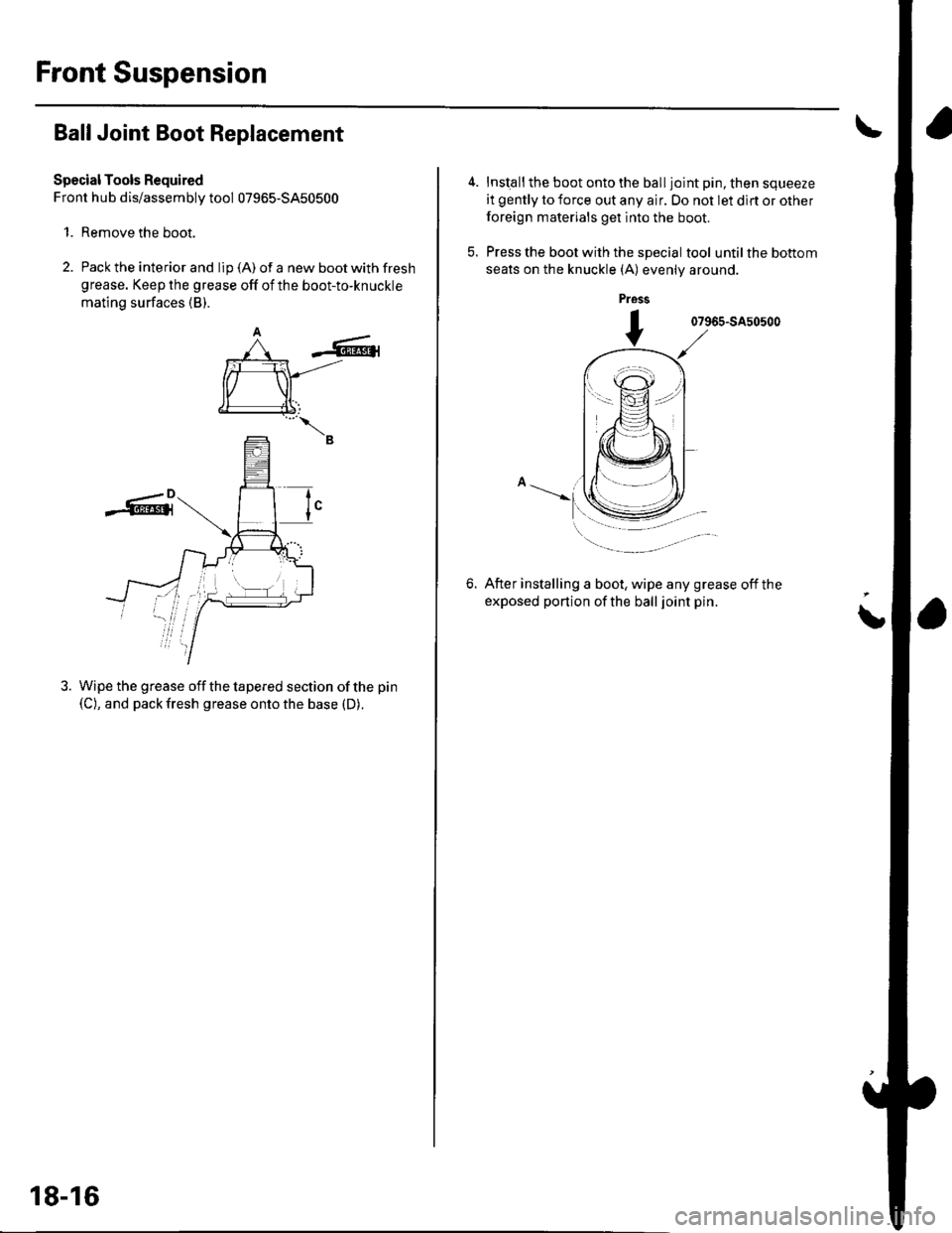
2. Pack the interior and lip (A) of a new boot with fresh
grease. Keep the grease off of the boot-to-knuckle
mating surfaces (B).
-6r
rffi
€l
--B
Wipe the grease off the tapered section of the pin
(C), and pack fresh grease onto the base (D).
tI
18-16
Inst€ll the boot onto the ball joint pin, then squeeze
it gently to force out any air. Do not let dlrt or other
foreign materials get into the boot.
Press the boot with the special tool until the bottom
seats on the knuckle (A) evenly around.
pross
07965-SA50500
6.After installing a boot, wipe any grease off the
exposed portion of the ball joint pin.
i
Page 575 of 1139
Stabilizer Bar Replacement
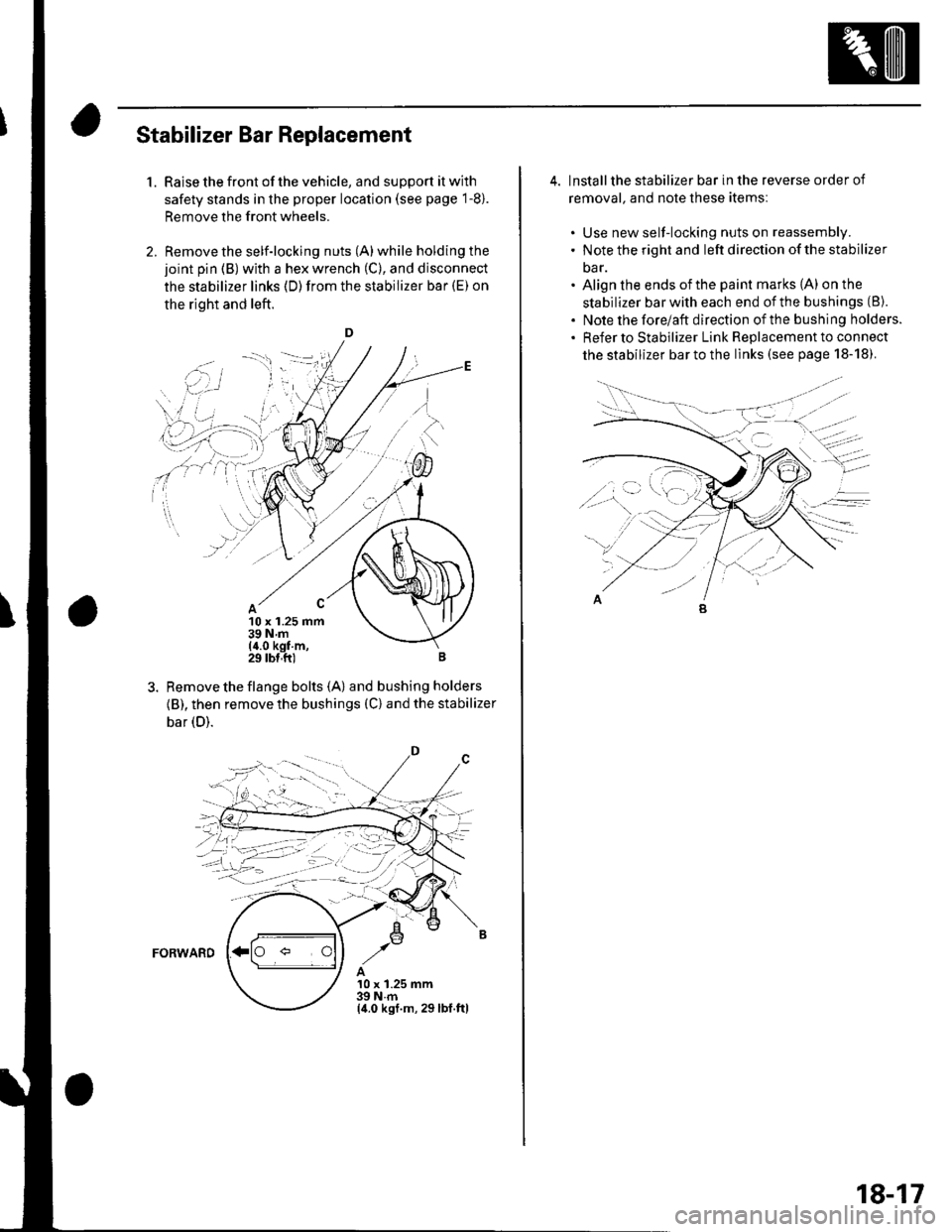
1.Raise the front of the vehicle, and support it with
safety stands in the proper location (see page 1-8).
Remove the front wheels.
Remove the self-locking nuts (A) while holding the
joint pin (B) with a hex wrench (C), and disconnect
the stabilizer links (D)from the stabilizer bar (E) on
the right and left.
D
10 x 1.25 mm39Nm(4.0 kgf m,29 tbl,ft)
Remove the flange bolts {A) and bushing holders
{B), then remove the bushings (C) and the stabilizer
bar (D).
FORWARD
A10 x 1.25 mm39Nm(4.0 ksf.m, 29lbl.ftl
,.'i i
''i]
. i.',.:-l I
\' ,r' ,' i :..r'j-- r-'1 _: i'
i-ii::;i
;4-llt,-'j--;
4. lnstallthe stabilizer bar in the reverse order of
removal. and note these itemsl
. Use new self-locking nuts on reassembly.. Note the right and left direction of the stabilizer
oar.. Align the ends ofthe paint marks (A) on the
stabilizer bar with each end of the bushings (8).
. Note the forelaft direction ofthe bushing holders.. Refer to stabilizer Link Replacement to connect
the stabilizer bar to the links (see page 18-18).
18-17