HONDA CIVIC 2003 7.G Workshop Manual
CIVIC 2003 7.G
HONDA
HONDA
https://www.carmanualsonline.info/img/13/5744/w960_5744-0.png
HONDA CIVIC 2003 7.G Workshop Manual
Trending: reset, Intake manifold removal, radiator, catalytic converter, Engine type, egr valve, interior light
Page 491 of 1139
Driveline/Axle
Intermediate Shaft Reassembly
(cont'd)
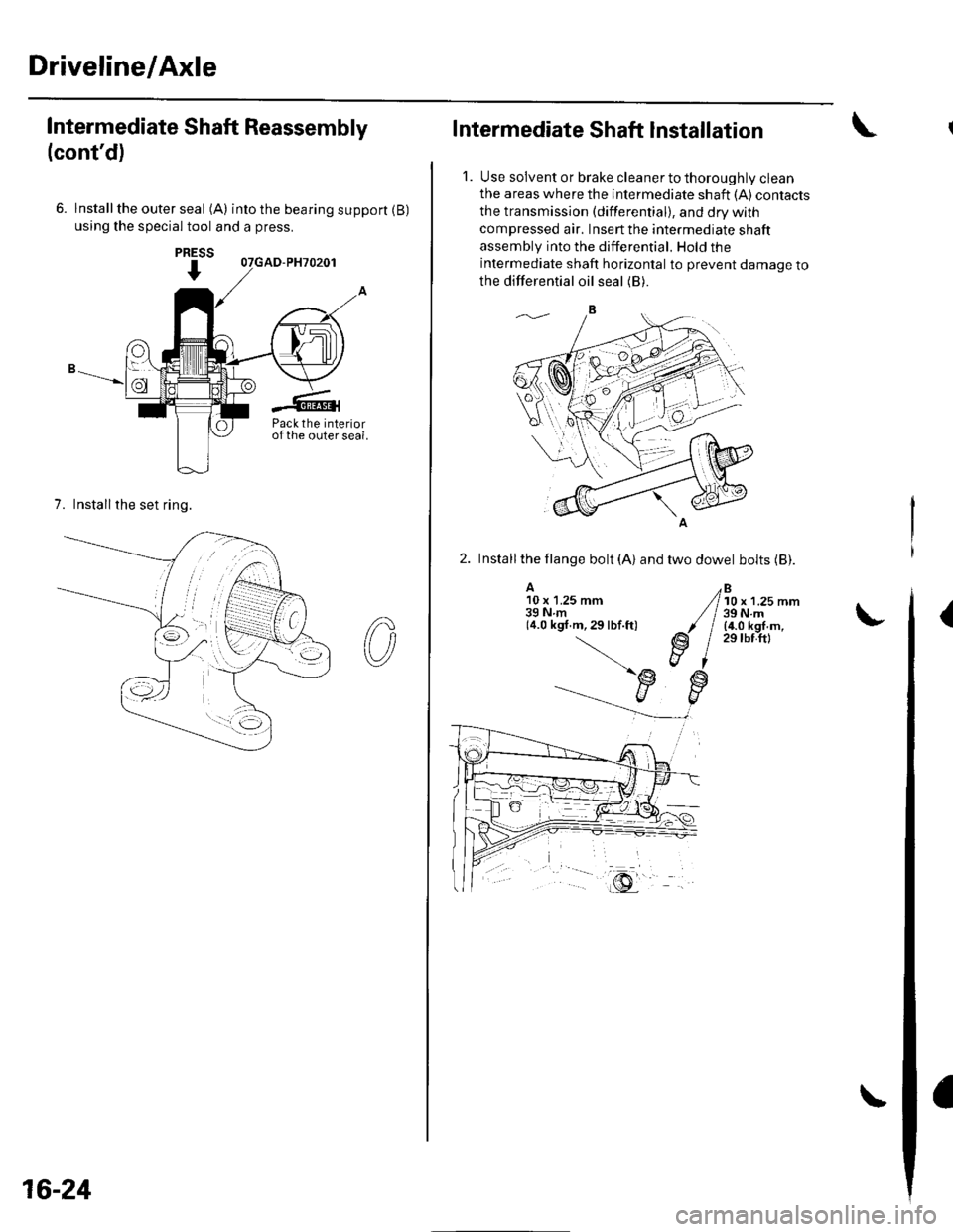
6. lnstallthe outer seal (A) intothebearingsupport(B)
using the special tool and a press.
7. Installthe set ring.
PRESS
I
Pack the interiorofthe outer seal.
16-24
Intermediate Shaft Installation
1. Use solvent or brake cleaner to thoroughly clean
the areas where the intermediate shaft {A) contacts
the transmission (differential), and dry with
compressed air. Insert the intermediate shaft
assembly into the differential. Hold the
intermediate shaft horizontal to prevent damage to
the differential oil seal (B).
2. Installthe llange bolt (A) and two dowel bolts (Bl.
A10 x 1.25 mm39Nm(4.0 kgf.m,29lbf.ft)
Bl0 x 1.25 mm39 N.m(4.0 kgf.m,29 tbf.ftl
(
Page 492 of 1139
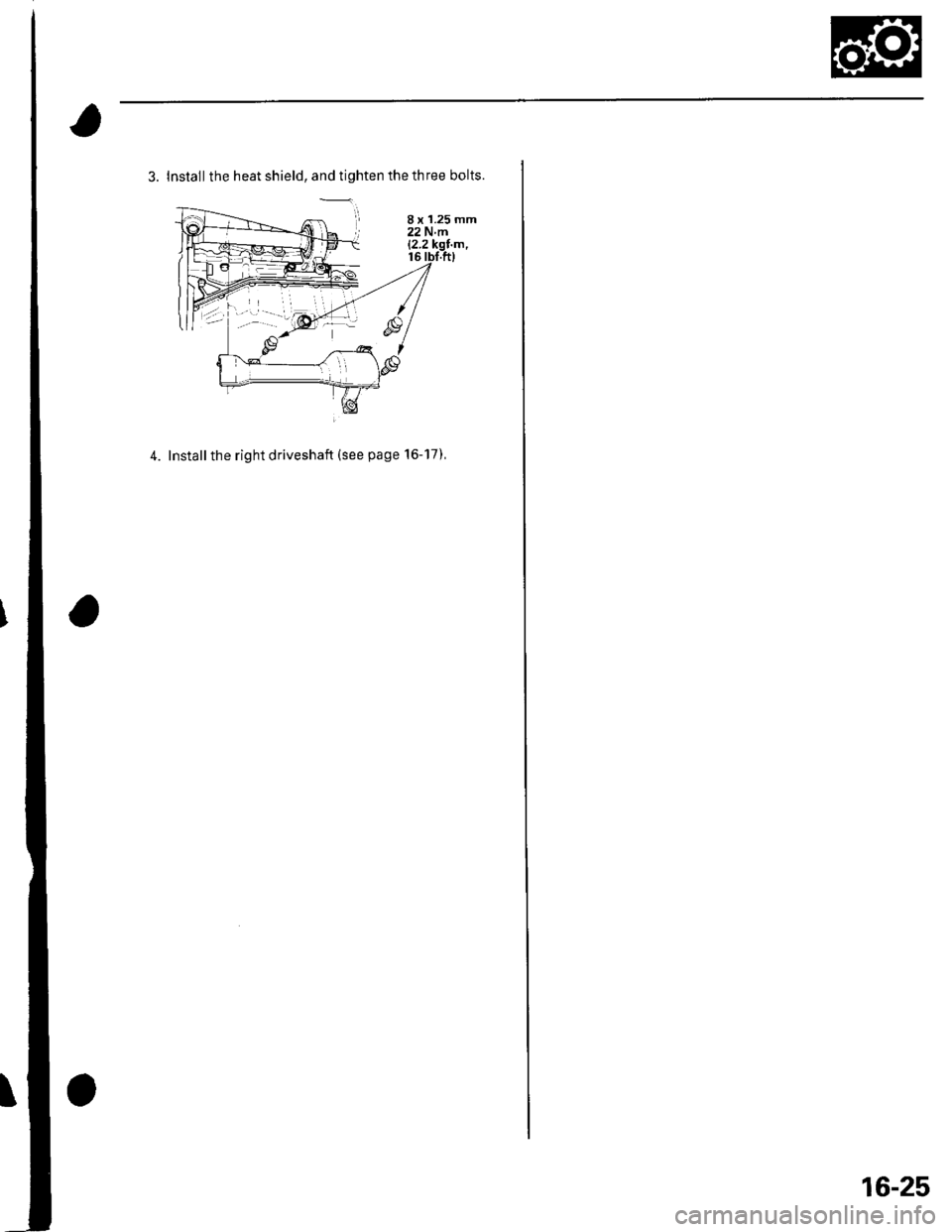
3. Install the heat shield, and tighten the three bolts.
4. Installthe right driveshaft (see page 16-17),
8 x 1.25 mm22Nm12.2
16-25
Page 493 of 1139
Steering
Steering
Special Tools ............. 17-2
Comoonent Location Index ......................................... 17-3
Steering Wheel Rotational Play Check .....................". 17-4
Power Assist Check .................. .......... 17-4
Steering Linkage and Gearbox Inspection ................. 17-5
Steering Wheel Removal .........................,................... 17-6
Steering Wheel Disassembly/Reassembly ................ 17-7
Steering Wheel Installation ............... 17-8
Steering Column Removal and Installation ...........'... 17-9
Steering Column Inspection .............. 17-11
Steering Lock Replacement .......................................'. 17-'12
Rack Guide Adiustment ....."........'..'.. 17-13
Electrical Power Steering (EPS)17-15
Page 494 of 1139
Steering
SpecialTools(
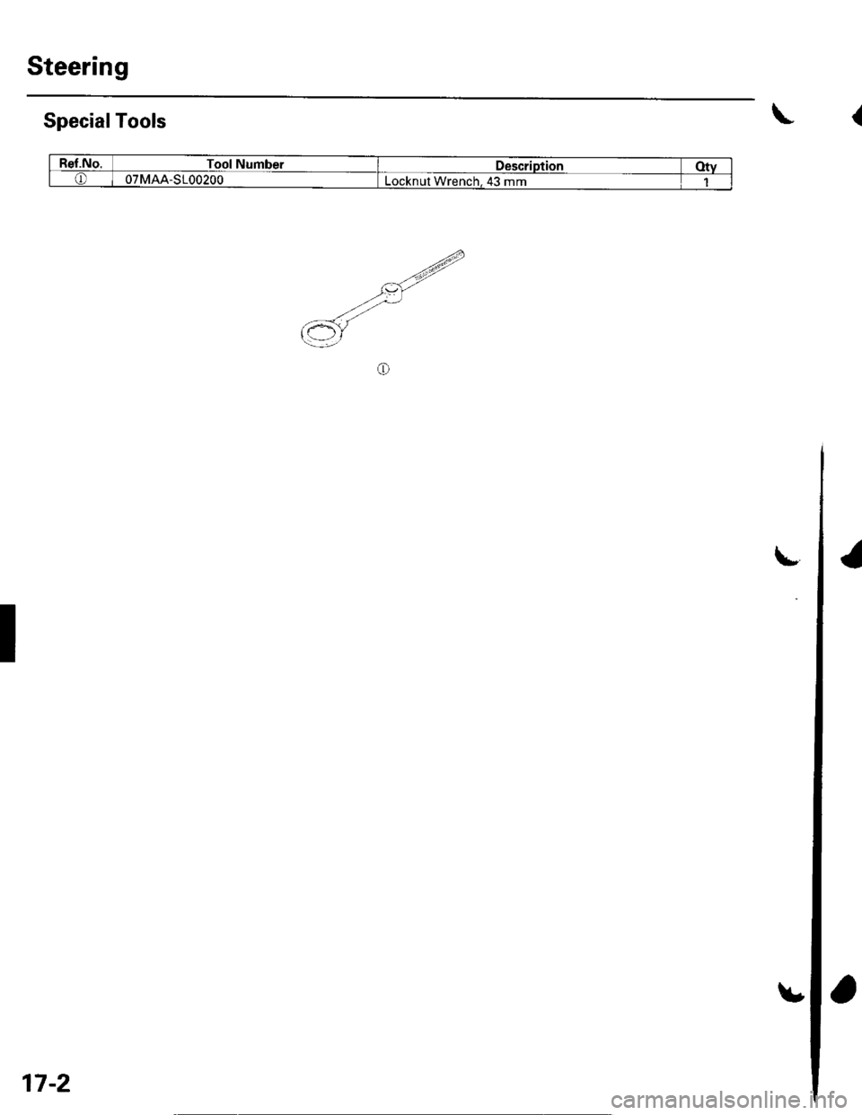
Ref.No.Tool NumberDescriptionOtyo07MAA-S100200Locknul Wrench. 43 mm
E-.tt)----<,/L\2 r
.V-
6Y
o
I
17-2
Page 495 of 1139
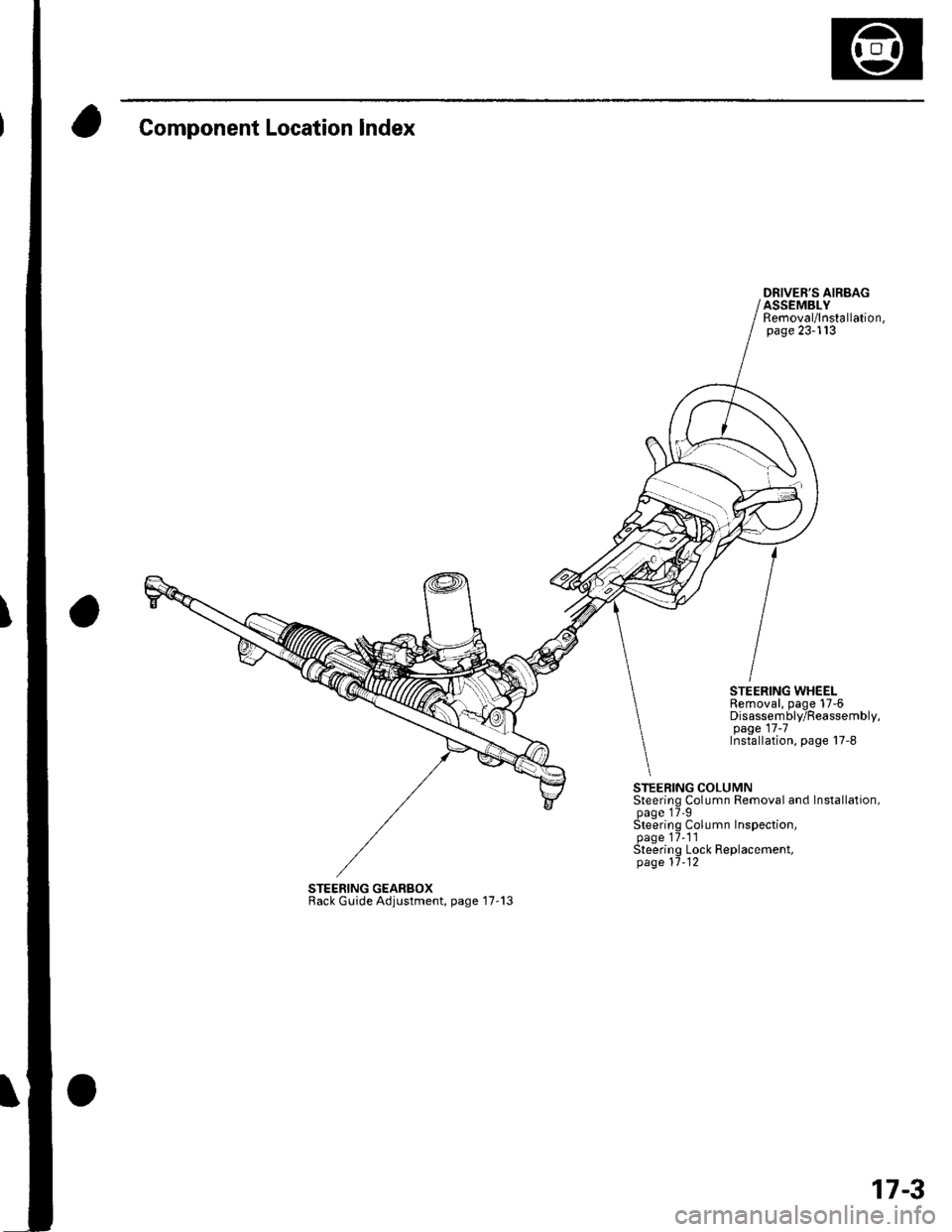
Component Location Index
DRIVER'S AIRBAGASSEMBLYRemoval/lnstallation,page 23-113
STEERING WHEELRemoval, page 17-6Disassembly/Reassembly,page 17 -7Installation, page 17-8
STEERING COLUMNSteering Column Removal and Installation,page 17'9Steering Column Inspection,page 17-1'lSteering Lock Replacement,page 11-12
STEERING GEARBOXRack Guide Adjustment, page '17-13
17-3
Page 496 of 1139
Steering
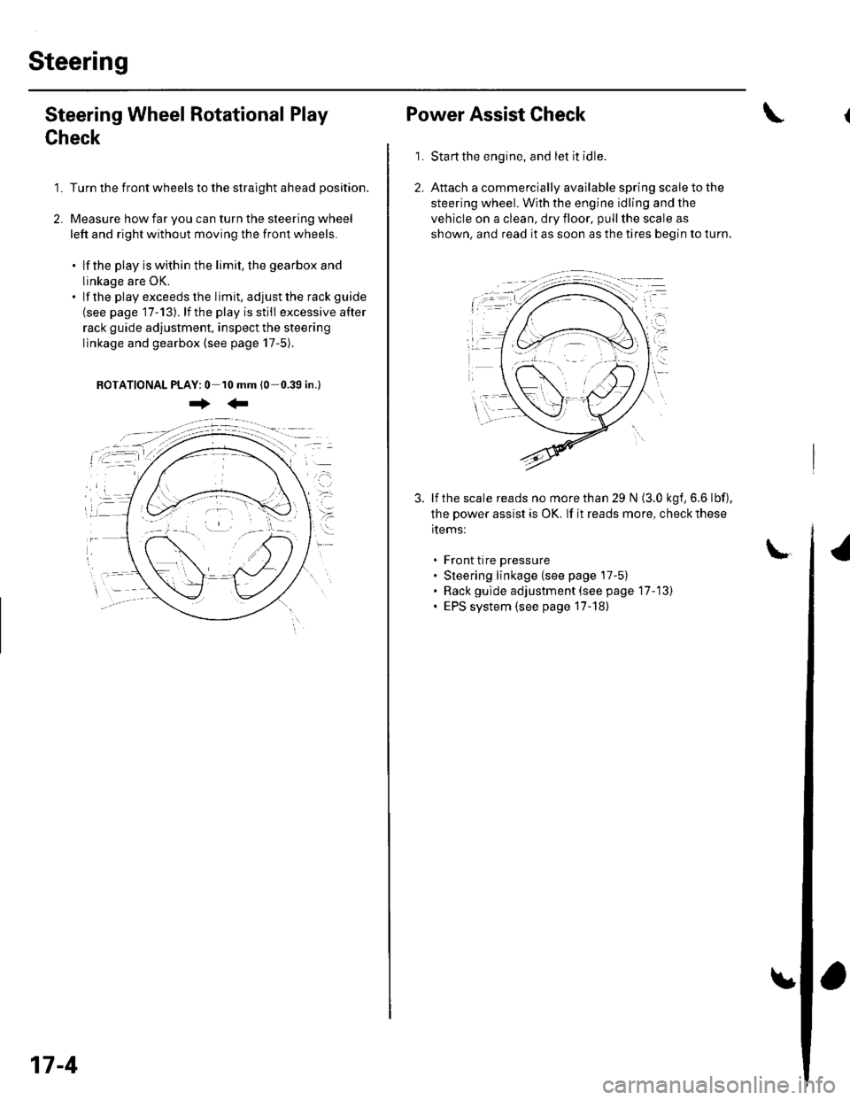
Steering Wheel Rotational Play
Check
1. Turn the front wheels to the straight ahead position.
2. Measure how far you can turn the steering wheel
left and right without moving the front wheels.
. lf the play is within the limit, the gearbox and
linkage are OK.. lf the playexceedsthe limit, adjustthe rack guide
{see page '17-13). lf the play is still excessive after
rack guide adjustment, inspect the steering
linkage and gearbox {see page 17-5).
BOTATIONAL PLAY: 0 10 mm (0-0.39 in.l
+:
17-4
Power Assist Check
Start the engine, and let it idle.
Attach a commercially available spring scale to the
steering wheel. With the engine idling and the
vehicle on a clean, dry floor, pull the scale as
shown, and read it as soon as the tires begin to turn.
\
1.
3. lf the scale reads no morethan 29 N (3.0 kgf,6.6 lbf),
the power assist is OK. lf it reads more, check these
items:
. Front tire pressure. Steering linkage (see page 17-5). Rack gulde adjustment (see page 17-13). EPS system (see page 17-18)
Page 497 of 1139
I
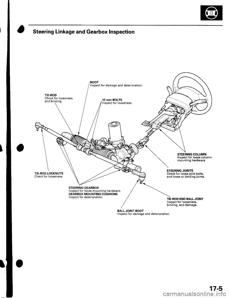
Steering Linkage and Gearbox Inspection
Check for looseness,and binding.
TIE.ROD LOCKNUTSCheck for looseness.
BOOTInspect Ior damage and deterioration.
12 mm BOLTSInspect for looseness.
STEERING COLUMNInspect for loose columnmounting hardware
STEERING GEARBOXInspect for loose mounting hardware.GEARBOX MOUNTING CUSHIONSInspect for deterioration.
STEERING JOINTSCheck for loose ioint bolts,and loose or binding ioints.
TIE.ROD ENO BALL JOINTlnsoect tor looseness,binding, and damage.
BALLJOINT BOOTInspect for damage and deterioration.
17-5
Page 498 of 1139
Steering
Steering Wheel Removal
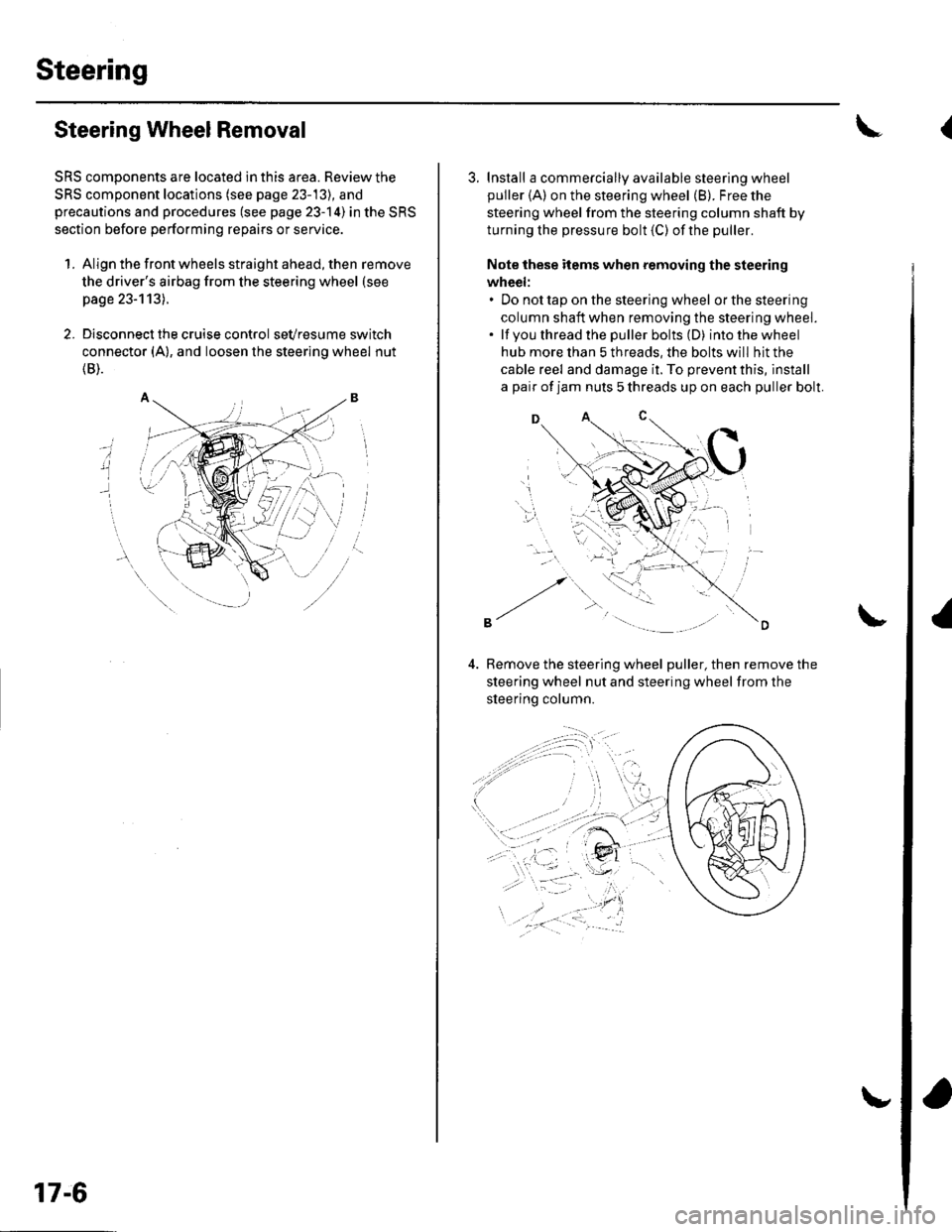
SRS components are located in this area. Review the
SRS component locations (see page 23-13), and
precautions and procedures (see page 23-14) in the SRS
section before performing repairs or service.
1. Align the front wheels straight ahead, then remove
the driver's airbag from the steering wheel (see
page 23-113).
2. Disconnect the cruise control sevresume switch
connector (A), and loosen the steering wheel nut
{B).
i
17-6
3. Install a commercially available steering wheel
puller {A) on the steering wheel (B). Free the
steering wheel from the steering column shaft by
turning the pressure bolt (C) ofthe puller.
Note these items when removing the steering
wheel:. Do not tap on the steering wheel orthesteering
column shaft when removing the steering wheel.. lf you thread the puller bolts (D) intothewheel
hub more than 5 threads, the bolts will hit the
cable reel and damage it. To prevent this, install
a pair of jam nuts 5 threads up on each puller bolt.
D
Bemove the steering wheel puller, then remove the
steering wheel nut and steering wheel from the
sleerino column.
{
Page 499 of 1139
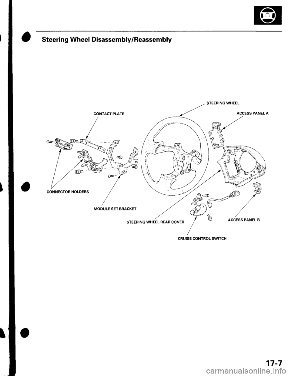
Steering Wheel Disassembly/Reassembly
CONTACT PLATE
MOOULE SET BRACKET
STEERING WHEEL REAB COVER
STEERING WHEEL
ACCESS PANEL A
75*-=offi
,/*
ffi)Y /-f
b accEss PANEL B
CRUISE CONTROL SWITCH
CONNECTOR HOLDERS
17-7
Page 500 of 1139
Steering
Steering Wheel Installation
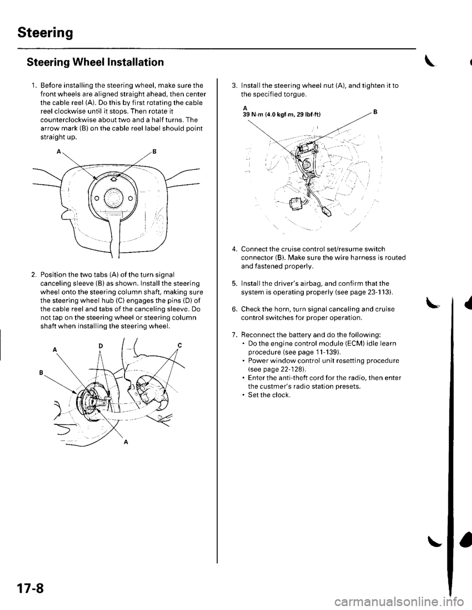
1. Before installing the steering wheel, make sure the
front wheels are aligned straight ahead, then center
the cable reel (A). Do this by first rotating the cable
reel clockwise until it stops. Then rotate it
counterclockwise about two and a half turns. The
arrow mark (B) on the cable reel label should point
straight up.
Position the two tabs (A) of the turn signal
canceling sleeve (B) as shown. Installthe steering
wheel onto the steering column shaft, making sure
the steerlng wheel hub (C) engages the pins (D) of
the cable reel and tabs of the canceling sleeve. Do
not tap on the steering wheel or steering column
shaft when installing the steering wheel.
17-8
3. Install the steering wheel nut (A), and tighten it to
the specified torgue.
A_B39 N.m (4.0 kgf m.29lbt ftl
Connect the cruise control set/resume switch
connector (B). fvlake sure the wire harness is routed
and fastened properly.
Install the driver's airbag, and confirm that the
system is operating properly {see page 23-113).
Check the horn, turn signal canceling and cruise
control switches for proper operation.
Reconnect the battery and do the following:. Do the engine control module (ECM) idle learn
procedure (see page 1l-139),. Power window control unit resetting procedure
\see page 22-1281.. Enter the anti-theft cord for the radio, then enter
the custmer's radio station presets.. Set the clock.
{
7.
lr,',,t
;. _,:!
'' '1i::..'.' l
Trending: Top dead center, Clutch, spare tire, fuse control box removal, height, Engine removal, check engine
