HONDA CIVIC 2003 7.G Workshop Manual
CIVIC 2003 7.G
HONDA
HONDA
https://www.carmanualsonline.info/img/13/5744/w960_5744-0.png
HONDA CIVIC 2003 7.G Workshop Manual
Trending: Oil, parking brake, Head removal, battery location, differential, Compressor clutch circuit, fuel fill door release
Page 461 of 1139
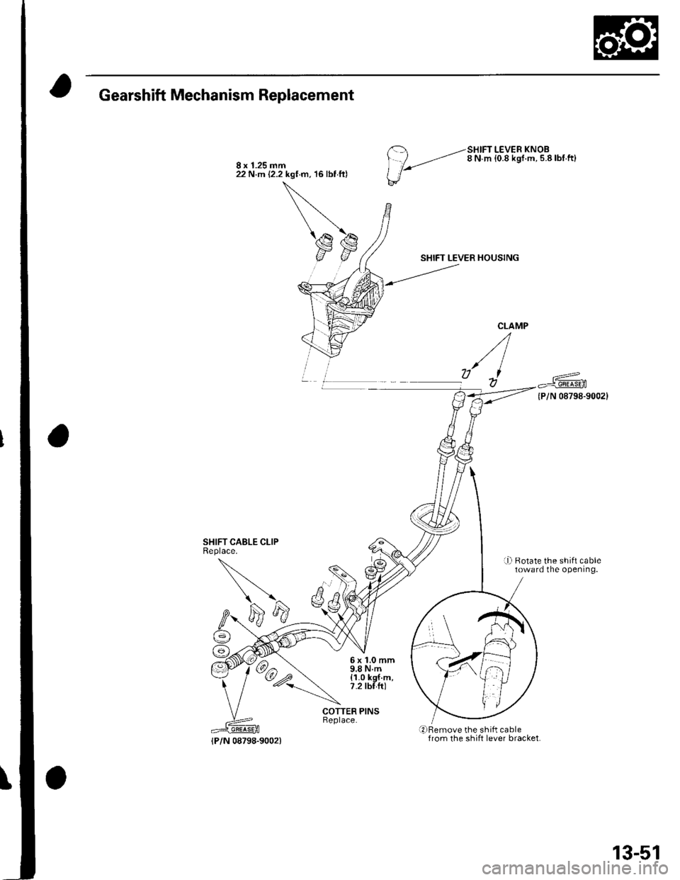
Gearshift Mechanism Replacement
SHIFT CABLE CLIPReplace.
8 x 1.25 mm22 N.m (2.2 kgf.m, 16 lbt ftl
--SHIFT LEVER KNOB
/ ,.-,'-' 8 N m {0.8 ksr.m. 5.8lbf.ft}
l'/
SHIFT LEVER HOUSING
{P/N 08798-9002}
r-Ll Rotate the shift cabletoward the opening.
6x1.0mm9.8Nm(1.0 kgf.m,7.2 tbf.fr)
COTTER PINS
qrBemove the shift cablefrom the shift lever bracket.{P/N 08798-9002)
13-51
Page 462 of 1139
M/T Differential
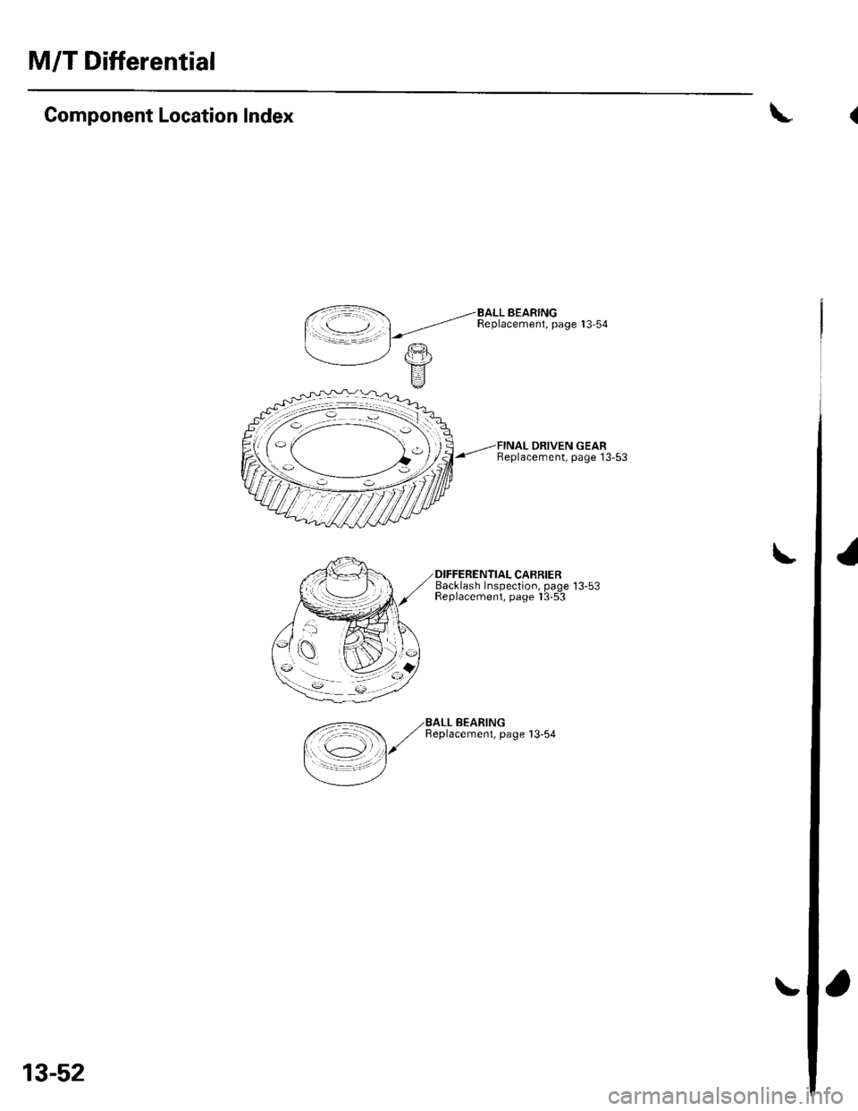
Component Location Index
DRIVEN GEARBeplacement, page 13-53
Backlash Insoection. oaoe 13-53Feplacemeni, paoe I 3-5-3
\
\
,<-=- ,/BALL BEARING
/ ,/ Beplacemenl, page 13-54
I \c1 l/
=/
13-52
(
I
Page 463 of 1139
\
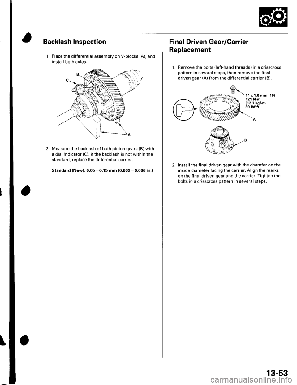
Backlash lnspection
1.Place the differential assembly on V-blocks (A), and
install both axles.
Measure the backlash of both pinion gears (B) with
a dial indicator (C). lf the backlash is not within the
standard, replace the differential carrier.
Standard (New): 0.05 0.15 mm (0.002 0.006 in.)
Final Driven Gear/Carrier
Replacement
1. Remove the bolts (left-hand threads) in a crisscross
pattern in several steps, then remove the final
driven gear (A)from the differential carrier {B).
t x t.o mm {to)121 Nm(12.3 kgf m,89 rbt.ft)
Install the final driven gear with the chamfer on the
inside diameter facing the carrier. Align the marks
on the final driven gear and the carrier. Tighten the
bolts in a crisscross pattern in several steps.
13-53
Page 464 of 1139
M/T Differential
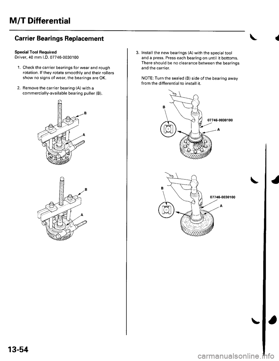
Carrier Bearings Replacement
Special Tool Bequired
Driver, 40 mm l.D. 07746-0030100
1. Check the carrier bearings for wear and rough
rotation. lf they rotate smoothly and their rollers
show no signs of wear, the bearings are OK,
2. Remove the carrier bearing (A) with a
commercially-available bearing puller (B).
13-54
\{
3. Install the new bearings (A)with the special tool
and a press. Press each bearing on until it bottoms.
There should be no clearance between the bearinos
and the carrier.
NOTE: Turn the sealed (B) side of the bearing away
from the differentialto install it.
077i16-0030100
07746-0030100
6
Page 465 of 1139
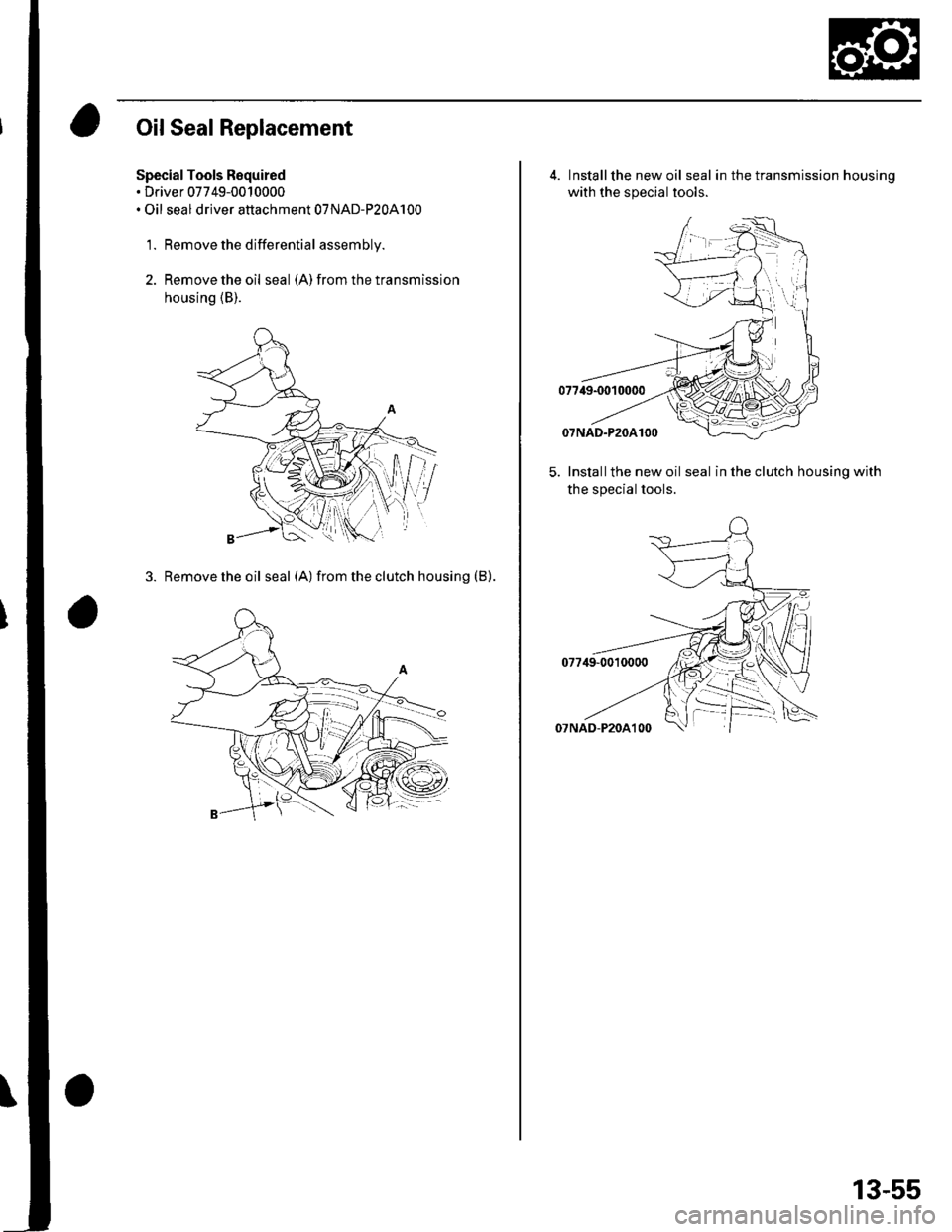
Oil Seal Replacement
Special Tools Required. Driver 07749-0010000. Oil seal driver attachment 07NAD-P20A100
1. Remove the differential assembly.
2. Remove the oil seal (A) from the transmission
housing (B).
3. Removetheoil seal (A) fromtheclutch housing (B).
4. Installthe new oil seal in the transmission housinq
with the special tools.
5. Installthe new oil seal in the clutch housing with
the special tools.
13-55
Page 466 of 1139
M/T Differential
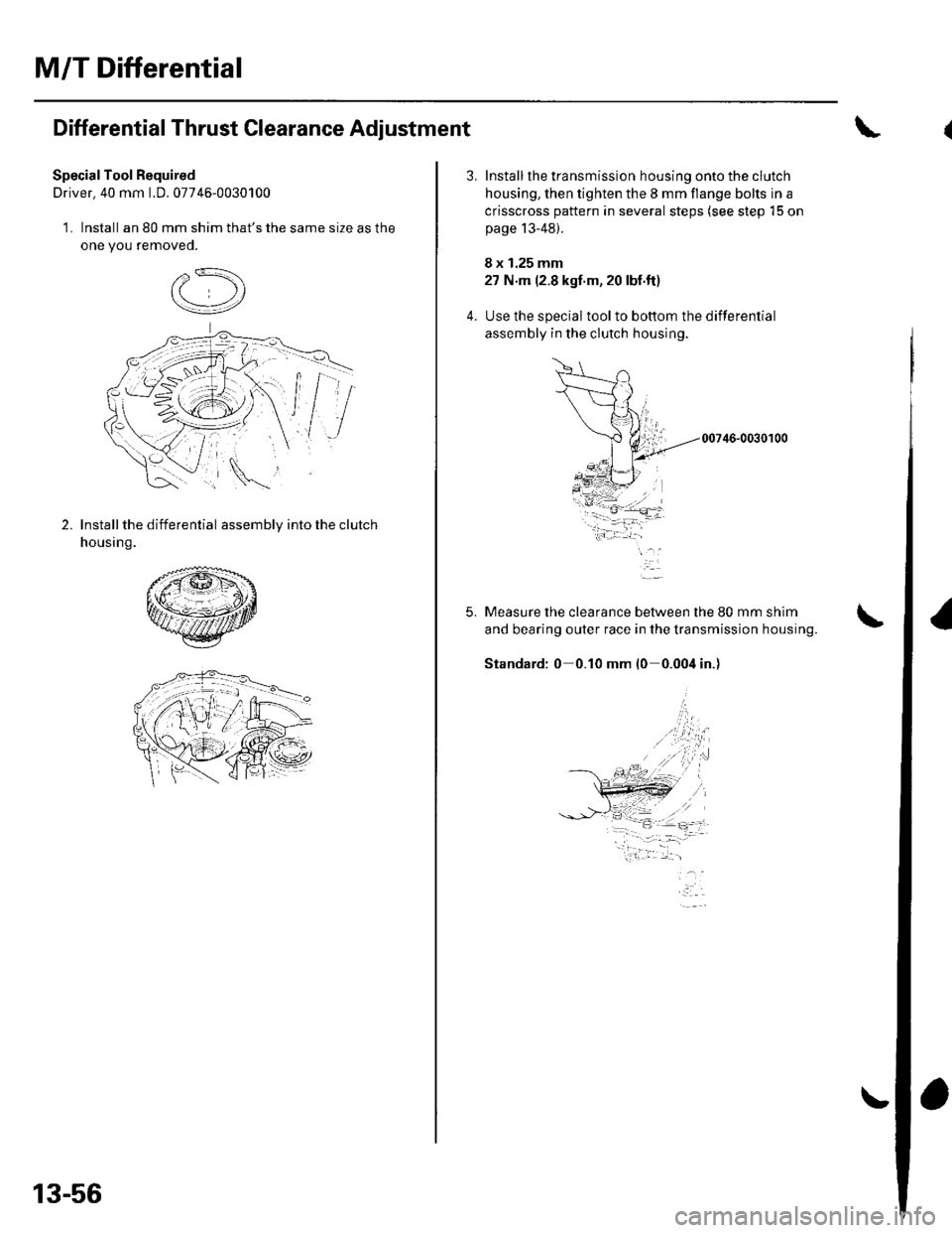
Differential Thrust Clearance Adjustment
SpecialTool Required
Driver. 40 mm LD. 07746-0030100
1. Install an 80 mm shim that's the same size as the
one you removeo.
2.Install the differential assembly into the clutch
housing.
13-56
5.
Install the transmission housing onto the clutch
housing, then tighten the 8 mm flange bolts in a
crisscross pattern in several steps (see step 15 on
page 13-48).
8 x 1.25 mm
27 N m (2.8 kgf'm, 20 lbf.ft)
Use the special toolto bottom the differential
assembly in the clutch housing.
00746-0030100
Measure the clearance between the 80 mm shim
and bearing outer race in the transmission housing.
Standard: 0 0.10 mm l0 0.004 in.)
-i.w.t ..1-- -- :,- -=.
Page 467 of 1139
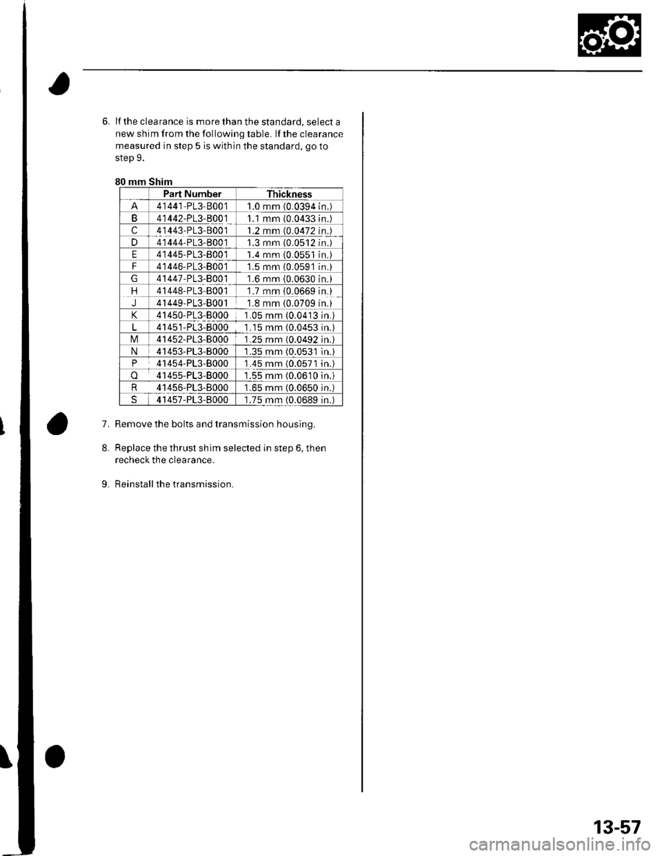
6. lf the clea rance is more than the standard, select a
new shim from the following table. lf the clearance
measured in step 5 is within the standard, go to
step 9.
80 mm Shim
Part NumberThickness
41441 PL3-80011.0 mm (0.0394n.
B41442-PL3-B00111 mm (0.0433n.
c41443-PL3-80011.2 mm (0.0472n.
D41444-PL3-B0011.3 mm {0.0512n.
E41445-PL3-800 11.4 mm 10.0551n.
F41446-PL3-80011.5 mm {0.0591n.
41447-PL3-800 11.6 mm (0.0630n.
rt41448-PL3-B0011.7 mm {0.0669n.
J41449-PL3-80011.8 mm (0.0709n.
41450-PL3-80001 .05 mm (0.0413n.)
41451-PL3-80001 .15 mm (0.0453n.l
tvl41452-PL3-80001.25 mm (0.0492n.l
N41453-PL3-80001.35 mm (0.053'ln.)
P41454-PL3-80001 .45 mm (0.0571n.l
o41455-PL3-80001.55 mm (0.0610n.)
R 41456-PL3-8000'1.65 mm (0.0650 in.)
41457-PL3-80001.75 mm (0.0689 in.)
7.Remove the bolts and transmission housing.
Replace the thrust shim selected in step 6, then
recheck the clearance.
Reinstall the transmission.
8.
9.
13-57
Page 468 of 1139
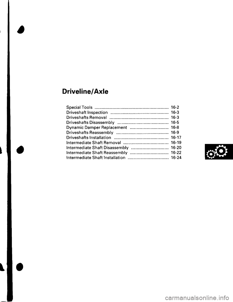
Driveline/Axle
SpecialTools ............. 16-2
Driveshaft Inspection ......................... 16-3
Driveshafts Removal .......................... 16-3
Driveshafts Disassembly ................... 16-5
Dynamic Damper Replacement ........ 16-8
Driveshafts Reassembly .................... 16-9
Driveshafts lnstallation ...................... 16-17
lntermediate Shaft Removal .............. 16-19
Intermediate Shaft Disassembly ................................. 16-20
lntermediate Shaft Reassembly .................................. 16-22
lntermediate Shaft lnstallation .................................... 16-24
Page 469 of 1139
Driveline/Axle
LSpecialTools
a\*
o@
tg r?)
[]
\J
,0)
Ref. No.Tool NumberDescriDtionOrv
n]
@
o
@
t9
6)
o(D
07GAD-PH70201
07MAC-S100200
07 NAF-SR30101
07xAc-001010A
07746-0010400
07746-0030400
07749-0010000
07947-S800100
Oil Seal Driver
BallJoint Remover, 28 mm
Half Shaft Base
Threaded Adapter, 22 x 1.5 mm
Attachment, 52 x 55 mm
uflver, J5 mm LU.
Driver
Oil Seal Driver
1
1
1
1
1
1
1
1
16-2
Page 470 of 1139
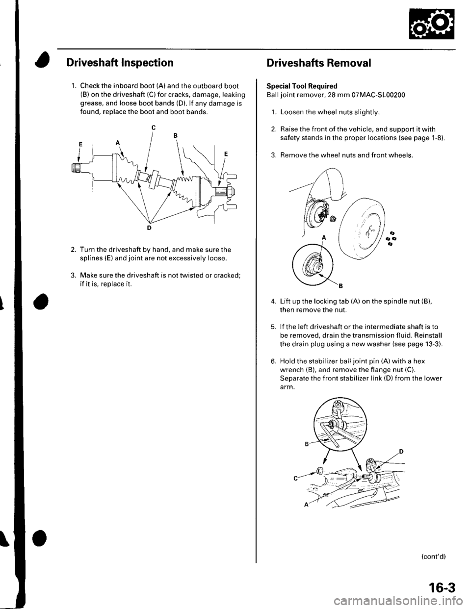
Driveshaft Inspection
1. Check the inboard boot (A) andthe outboard boot(B) on the driveshaft (C) for cracks, damage, leaking
grease, and loose boot bands (D). lf any damage is
found, reDlace the boot and boot bands.
Turn the driveshaft by hand, and make sure the
splines (E) and joint are not excessively loose.
Make sure the driveshaft is not twisted or cracked;
if it is, replace it.
Driveshafts Removal
Special Tool Required
Balljoint remover, 28 mm 07MAC-S100200
1. Loosen the wheel nuts slightly
2. Raise the front of the vehicle, and support it with
safety stands in the proper locations (see page 1-8).
3. Remove the wheel nuts and front wheels.
4.Lift up the locking tab (A) on the spindle nut (B),
then remove the nut.
lf the !eft driveshaft or the intermediate shaft is to
be removed, drain the transmission fluid. Reinstall
the drain plug using a new washer (see page 13-3).
Hold the stabilizer balljoint pin (A) with a hex
wrench {B), and remove the flange nut (C).
Separate the front stabilizer link (D) from the lower
a rm.
(cont'd)
16-3
Trending: resonator, child lock, run flat, spare tire, FUEL AND EMISSION, horn, headlight
![HONDA CIVIC 2003 7.G Workshop Manual Driveline/Axle
LSpecialTools
a\*
o@
tg r?)
[]
\J
,0)
Ref. No.Tool NumberDescriDtionOrv
n]
@
o
@
t9
6)
o(D
07GAD-PH70201
07MAC-S100200
07 NAF-SR30101
07xAc-001010A
07746-0010400
07746-0030400
07749-00 HONDA CIVIC 2003 7.G Workshop Manual Driveline/Axle
LSpecialTools
a\*
o@
tg r?)
[]
\J
,0)
Ref. No.Tool NumberDescriDtionOrv
n]
@
o
@
t9
6)
o(D
07GAD-PH70201
07MAC-S100200
07 NAF-SR30101
07xAc-001010A
07746-0010400
07746-0030400
07749-00](/img/13/5744/w960_5744-468.png)
