HONDA CIVIC 2003 7.G Workshop Manual
CIVIC 2003 7.G
HONDA
HONDA
https://www.carmanualsonline.info/img/13/5744/w960_5744-0.png
HONDA CIVIC 2003 7.G Workshop Manual
Trending: ecm, seats, plate light, Maintenance, under-dash, maintenance reset, FUEL AND EMISSION
Page 481 of 1139
Driveline/Axle
Driveshafts Reassembly (cont'dl
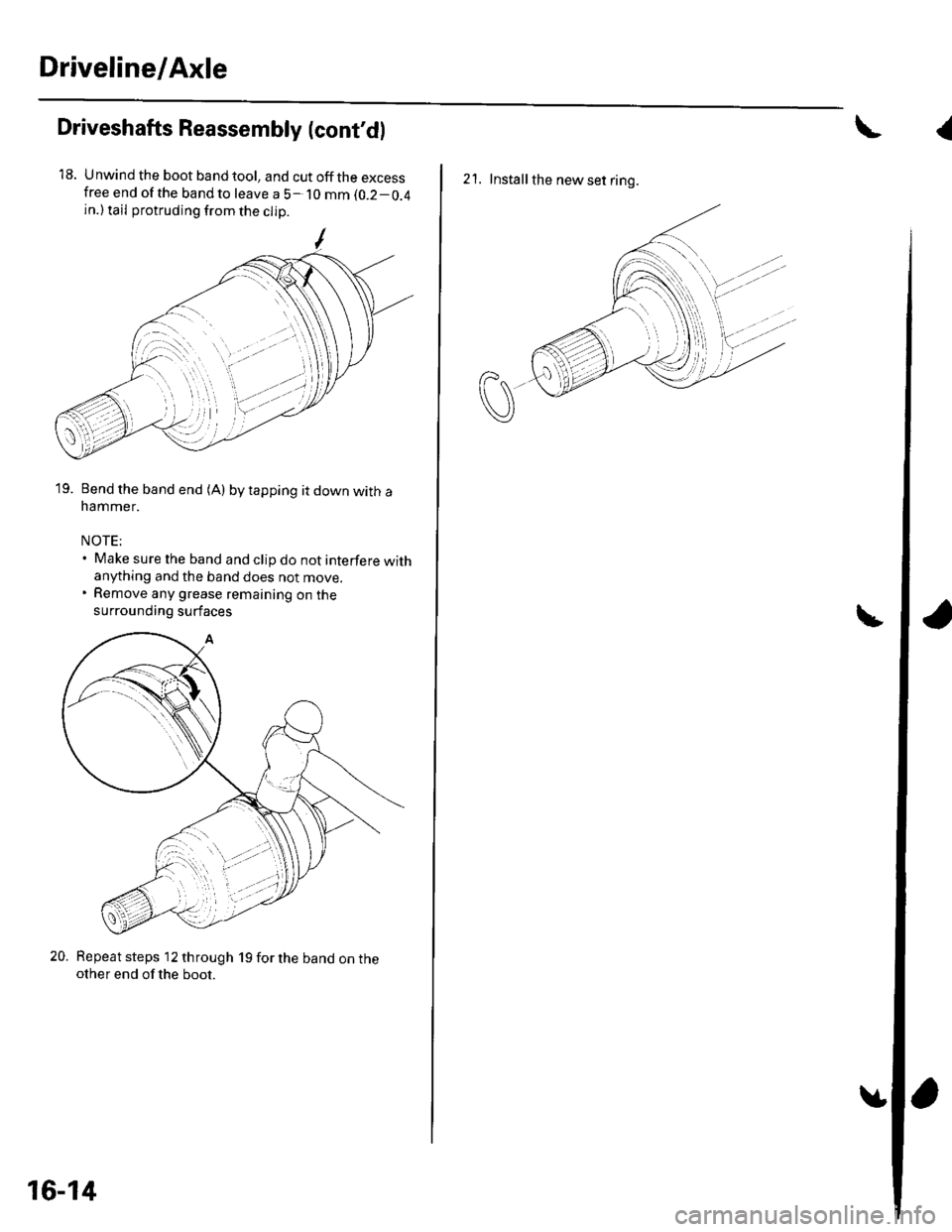
18. Unwind the boot band tool, and cut off the excessfree end of the bandto leave a 5- 10 mm (0.2-0.4
in.) tail protruding from the clip
19. Bend the band end (A) by tapping it down with anammer.
NOTE;. Make sure the band and clip do not interfere withanything and the band does not move.. Remove any grease remaining on the
surrounding surfaces
20. Repeat steps 12 through 19 for the band on theother end of the boot.
16-14
{
2'1. Installthe new set ring.
Page 482 of 1139
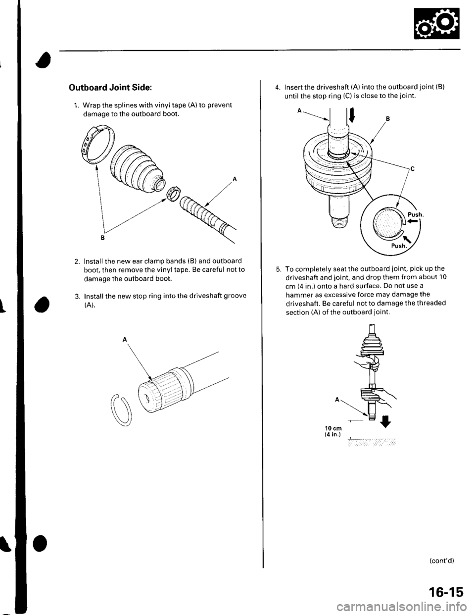
Outboard Joint Side:
1. Wrap the splines with vinyl tape (A) to prevent
damage to the outboard boot.
Installthe new ear clamp bands (B) and outboard
boot, then remove the vinyl tape. Be careful not to
damage the outboard boot.
Install the new stop ring into the driveshaft groove
(A).3.
t
4. Insert the driveshaft (A) into the outboard joint (B)
until the stop ring (C) is close to the joint.
To completely seat the outboard joint, pick up the
driveshaft and joint, and drop them from about 10
cm (4 in.) onto a hard surface. Do not use a
hammer as excessive force may damage the
driveshaft. Be careful not to damage the threaded
section (A) of the outboard joint.
5.
10 cm(4 in.)
- ..,..,1 ;,t ,:-,;
{cont'd)
16-15
Page 483 of 1139
Driveline/Axle
Driveshafts Reassembly (cont'd)
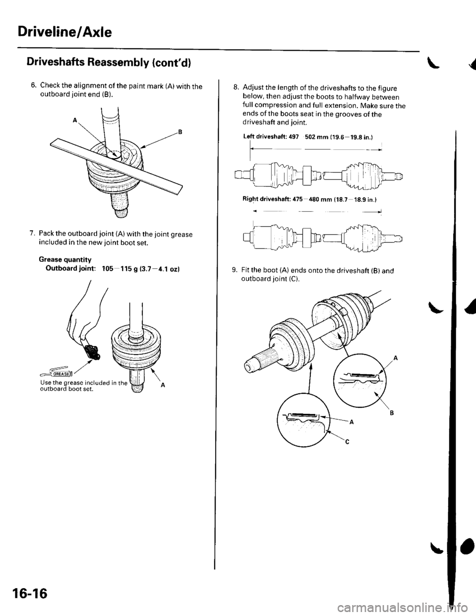
Check the alignment of the paint mark (A) with theoutboard joint end (B).
7. Pack the outboard joint (A)with the joint grease
included in the new ioint boot set.
Grease quantity
Outboard ioint: 105 115 g (3.7 4.1 ozl
/r
llt ,)
\{(
-*>
:;,"0'A?g.fff :l:f '., o "o
16-16
8. Adjust the length of the driveshafts to the figurebelow, then adjust the boots to halfway betweenfull compression and full extension. Make sure theends of the boots seat in the grooves of thedriveshaft and joint.
Left driveshaft:497 502 mm (19.6 19.8in.)
Rightdriveshaft: 475 480 mm {18.7
t
-tTfi'.D.ilTD
18.9 in.l
Fit the boot (A) ends onto the driveshaft (B) andoutboard joinl (C).
9.
{
Page 484 of 1139
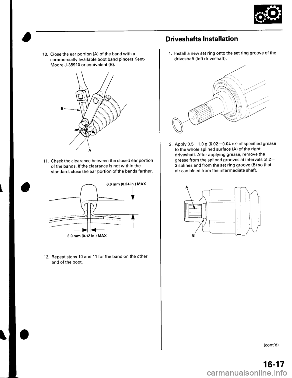
10. Close the ear portion (A) of the band with a
commercially available boot band pincers Kent-
Moore J-35910 or equivalent (B).
Check the clearance between the closed ear portlon
of the bands. lf the clearance is not within the
standard, close the ear podion of the bands farther.
11.
12.Repeat steps 10 and 11 for the band on the other
end of the boot.
6.0 mm 10.24 in.) MAX
3.0 mm {0.12 in.} MAX
Driveshafts Installataon
1. Install a new set ring onto the set ring groove of the
driveshaft {left driveshaft ).
Apply 0.5 1.0 g {0.02 0.04 oz) of specified grease
tothewhole splined surface (A) ofthe right
driveshaft. After applying grease, remove the
grease from the splined grooves at intervals of 2-
3 splines and from the set ring groove (B) so that
air can bleed from the intermediate shaft.
(cont'd)
16-17
Page 485 of 1139
Driveline/Axle
Driveshafts Installation (cont'd)
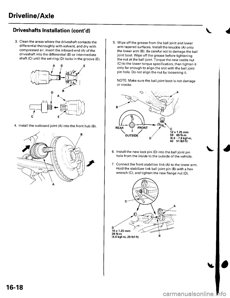
Clean the areas where the driveshaft contacts thedifferential thoroughly with solvent, and dry withcompressed air. Insenthe inboard end {A) ofthedriveshaft into the differential (B) or intermediateshaft {C) until the set ring (D) locks in the groove (E).
4. Install the outboard joint (A) into the front hub (B).
16-18
5. Wipe offthe grease from the ball ioint and lowerarm tapered surfaces. Installthe knuckle (A) ontothe lower arm {B). Be careful not to damage the balljoint boot. Wipe off the grease before tighteningthe nut at the ball joint. Torque the new castle nut(C) to the lower torque specification, then tighten itonly far enough to align the slot with the ball joint
pin hole. Do not align the nut by loosening it.
NOTE: Make sure the ball joint boot is not damageor cracks.
"-'t-
12 x 1.25 mm59 69 N.m(6.0 -7.0 kgf m,43 51 tbt.ftl
Installthe new lock pin {D) into the balljoint pin
hole from the inside to the outside of the vehicle.
Connect the front stabilizer link {A) to the lower arm.Hold the stabilizer link balljoint pin (B) with a hexwrench {C), and tighten the newflange nut {D).
7.
'10 x 1.25 mm39 N.m{4.0 kgf.m,29 lbf.ft)
{
Page 486 of 1139
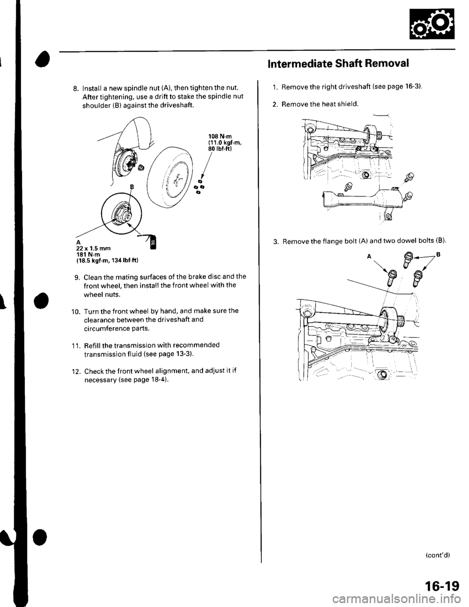
8. Install a new spindle nut {A), then tighten the nut.
After tightening, use a drift to stake the spindle nut
shoulder {B) against the driveshaft.
{18.5 kgf.m, 134lbt.ft)
9. Clean the mating surfaces ofthe brake disc and the
front wheel, then install the front wheel with the
wheel nuts.
10. Turn the front wheel by hand, and make sure the
clearance between the driveshaft and
circumference parts.
1 l. Refill the transmission with recommended
transmission fluid (see page 13-3).
12. Check the front wheel alignment, and adjust it if
necessary (see page 18-4).
108 N.m(11.0 kgf.m,80 tbt.ft)
/oooe
22x 1.5 mm181 N.m
1.
2.
lntermediate Shaft Removal
Remove the right driveshaft (see page 16-3).
Remove the heat shield.
3. Remove the flange bolt {A) andtwodowel bolts(B).
€.---2"EJ/
€w
(cont'd)
16-19
Page 487 of 1139
Driveline/Axle
{Intermediate Shaft Removal
(cont'dl
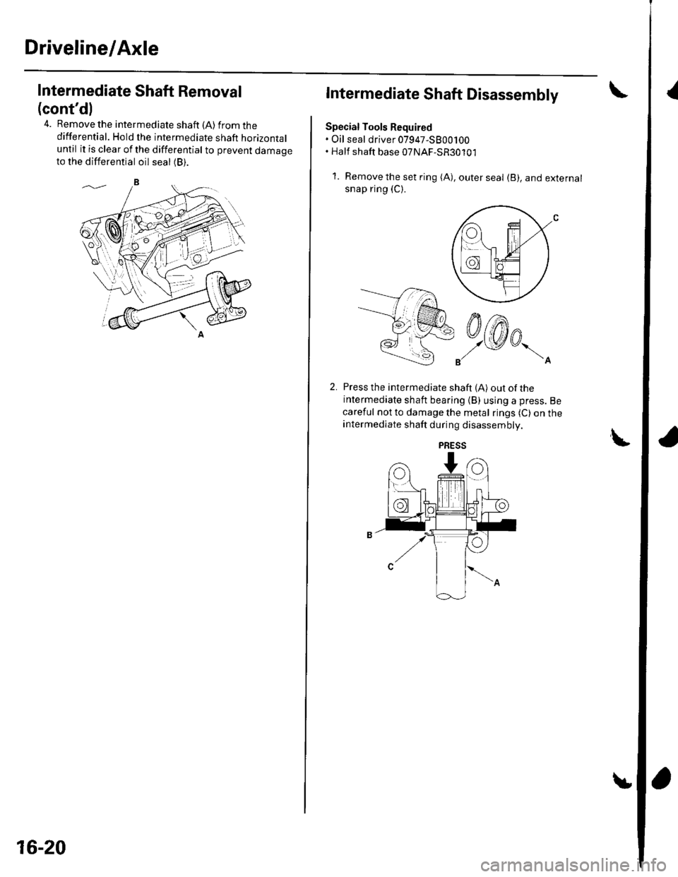
4. Remove the intermediate shaft (A) from thedifferential. Hold the intermediate shaft horizontaluntil it is clear of the differential to prevent damageto the differential oil seal (B).
16-20
Intermediate Shaft Disassembly
Special Tools Required. Oil seal driver 07947-5800100. Half shaft base 07NAF-SR30101
1. Removetheset ring (A), outerseal (B), and externalsnap ring (C).
Press the intermediate shaft (A) out of theintermediate shaft bearing (B) using a press. Be
careful not to damage the metal rings (C) on theintermediate shaft during disassembly.
LPRESS
Page 488 of 1139
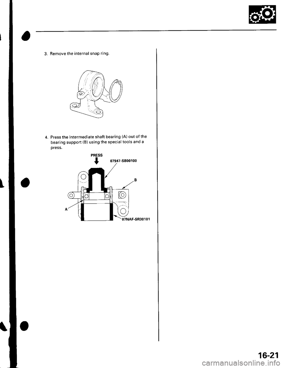
3. Remove the internal snap ring.
4. Press the intermediate shaft bearing (A) out of the
bearing support (B) using the special tools and a
oress.
07947-s800100
07NAF-SR30101
16-21
Page 489 of 1139
Driveline/Axle
Intermediate Shaft Reassembly
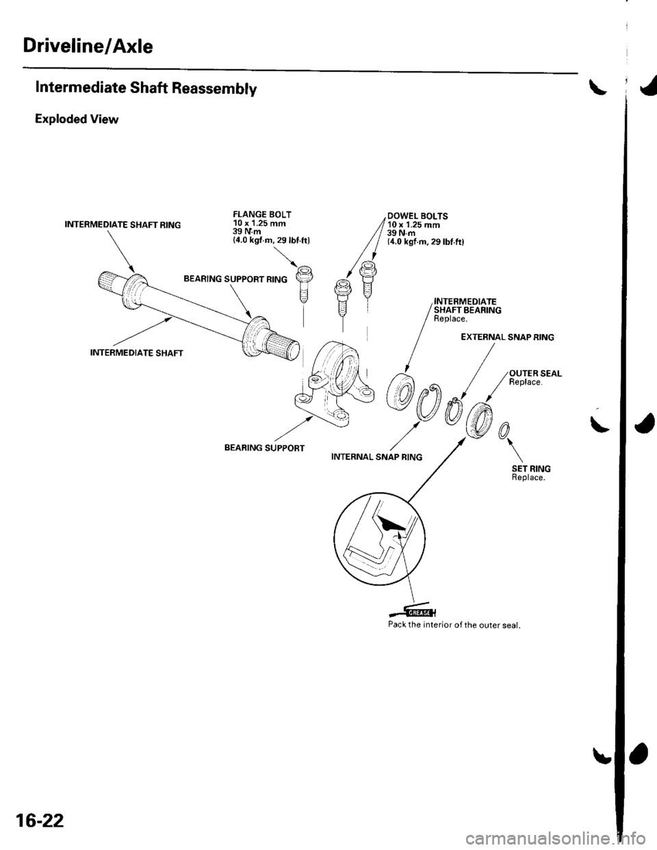
Exploded View
INTERMEDIATE SHAFT RING
FLANGE BOLT10 x '1.25 mm39IVm{4.0 kgf.m,29lbt.ftl
\^
,tto", *,"o p
\E--'+7\
BEARING SUPPOBT
Pack the interior of the outer seal.
16-22
Page 490 of 1139
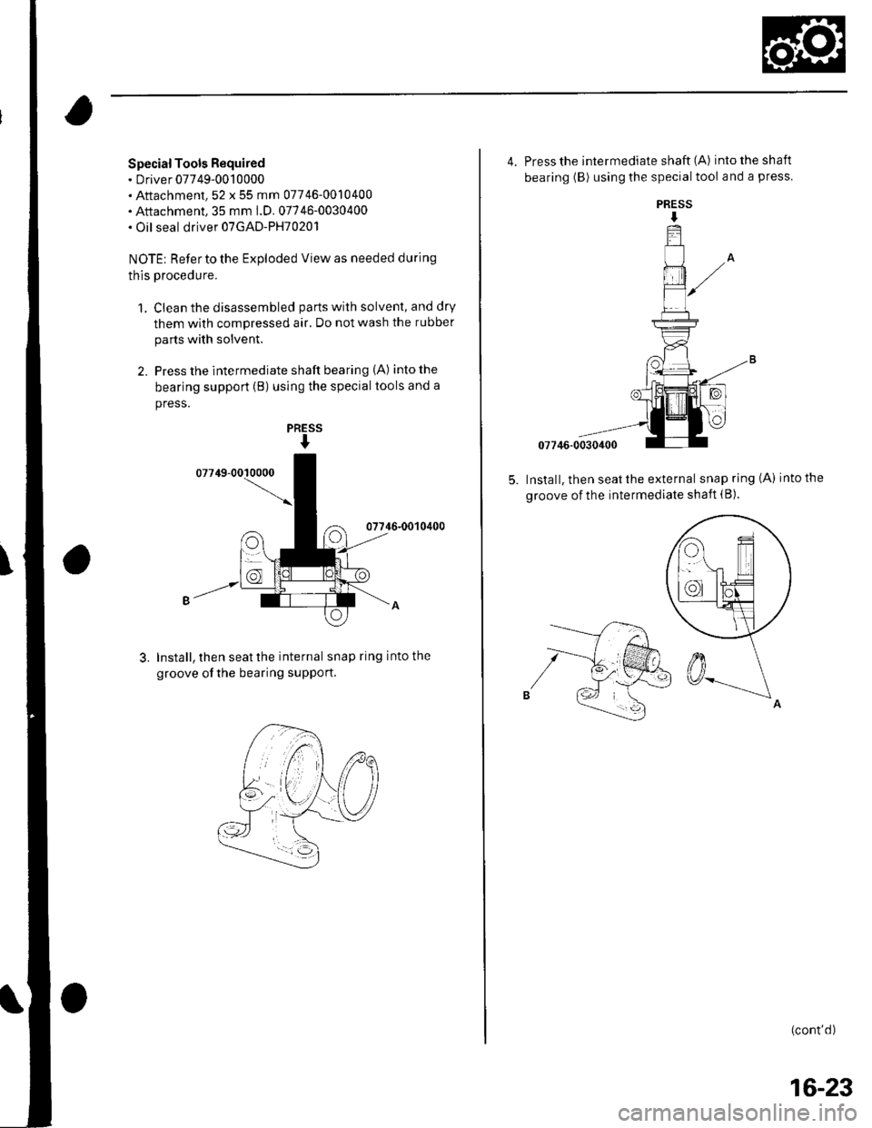
Special Tools Required. Driver 07749-0010000. Attachment,52 x 55 mm 07746-0010400. Attachment, 35 mm 1.D.07746-0030400. Oil seal driver 07GAD-PH70201
NOTE: Refer to the Exploded View as needed during
this procedure.
1. Clean the disassembled parts with solvent, and dry
them with compressed air. Do not wash the rubber
parts with solvent.
2. Press the intermediate shaft bearing (A) intothe
bearing support (B) using the special tools and a
press.
07746-0010400
Install, then seat the internal snap ring into the
groove ofthe bearing supPort.
ES
I
PR
3.
PRESS
I
4. Press the intermediate shaft (A) intotheshaft
bearing (B) using the special tool and a press.
07746-0030400
Install, then seat the external snap ring {A) into the
groove of the intermediate shaft (B).
(cont'd)
16-23
Trending: warning, air suspension, power window, 10-13, light, parking brake, radiator replace
