HONDA CIVIC 2003 7.G Workshop Manual
Manufacturer: HONDA, Model Year: 2003, Model line: CIVIC, Model: HONDA CIVIC 2003 7.GPages: 1139, PDF Size: 28.19 MB
Page 551 of 1139
EPS Components
{Steering Gearbox Overhaul (cont'dl
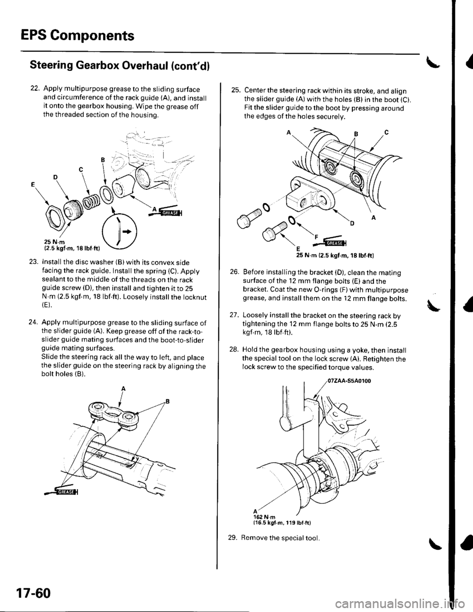
22. Apply multipurpose grease to the sliding surfaceand circumference ofthe rackguide (A), and installit onto the gearbox housing. Wipe the grease offthe threaded section ofthe housrno.
...'.
,. ,l
.j
23. Installthe disc washer (B)with its convex sidefacing the rack guide. Installthe spring (C). Appty
sealant to the middle of the threads on the rackguide screw (D), then install and tighten it to 25
N m (2.5 kgf.m, 18 lbf.ft). Loosely instatlrhe tocknut(E).
24. Apply multipurpose grease to the sliding surface ofthe slider guide (A). Keep grease off of the rack-to-slider guide mating surfaces and the boot-to-sliderguide mating surfaces.
Slide the steering rack all the way to left, and place
the slider guide on the steering rack by aligning thebolt holes (B).
'1 - .- =-1, -
17-60
29.
25. Centerthe steering rack within its stroke, and alignthe slider guide (A)with the hotes (B) in the boot (C).
Fit the slider guide to the boot by pressing around
the edges of the holes securely
E25 N.m 12.5 kgt.m, 18 tbt.ft)
26. Before installing the bracket (D), clean the mating
surface ofthe 12 mm flange bolts (E) and thebracket. Coat the new O-rings {F) with multipurposegrease, and installthem on the '12 mm flange bolts.
27. Loosely install the bracket on the steering rack bytightening the 12 mm flange bolts to 25 N.m (2.5
kgf.m, 18lbf.ft).
28. Hold the gearbox housing using a yoke, then install
the specialtool on the lock screw (A). Retighten thelock screw to the specified torque values.
{16.5 kgt.m, 119 lbf.ft}
Remove the special tool.
A
Page 552 of 1139
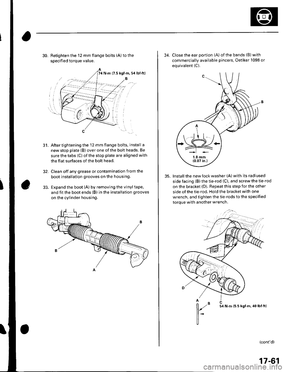
30, Retighten the 12 mm flange bolts (A) to the
soecified toroue value.
After tightening the 12 mm flange bolts, install a
new stop plate (B) over one of the bolt heads. Be
sure the tabs (C) of the stop plate are aligned with
the flat surfaces of the bolt head.
Clean off any grease or contamination from the
boot installation grooves on the housing.
Expand the boot (A) by removing the vinyltape,
and fit the boot ends (B) in the installation grooves
on the cylinder housing.
5t.
32,
74 N.m (7.5 kgf.m,5ir lbf.ft)
34. Close the ear portion (A) ofthe bands (B)with
commerciallv available pincers, Oetiker 1098 or
equivalent (C).
35. Installthe new lock washer (A) with its radiused
side facing (B) the tie-rod (C), and screw the tie-rod
on the bracket (D). Repeat this step for the other
side of the tie-rod. Hold the bracket with one
wrench, and tighten the tie-rods to the specified
torque with another wrench.
,,";=-...,.,
(cont'd)
*=,,',
17-61
Page 553 of 1139
EPS Components
Steering Gearbox Overhaul (cont'dl
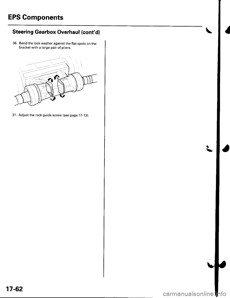
36. Bend the lock washer against the flat spots on thebracketwith a Iarge pair of pliers.
37. Adjust the rack guide screw {see page 17-13).
17-62
Page 554 of 1139
Steering Gearbox Installation
2.
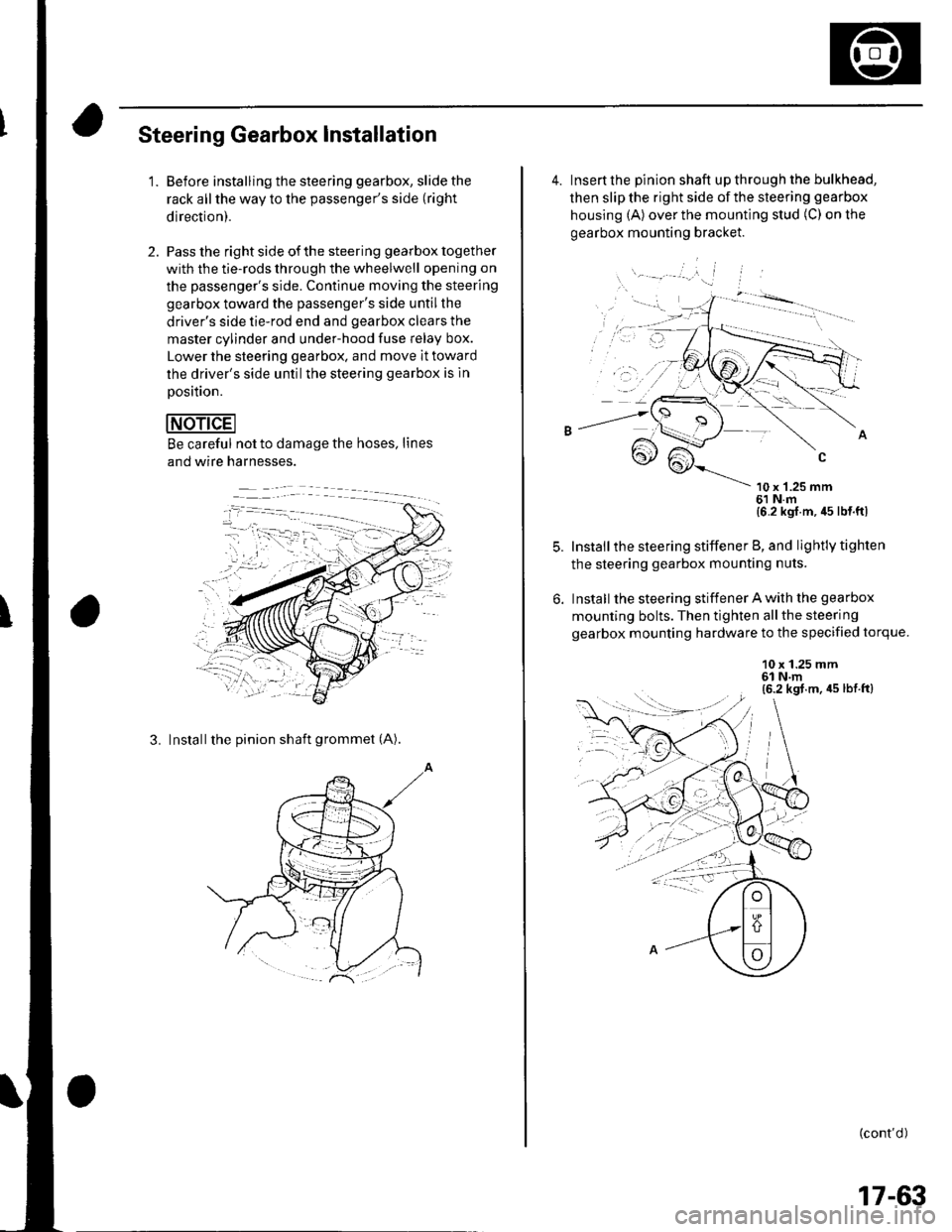
'1.Before installing the steering gearbox, slide the
rack all the way to the passenger's side (right
direction).
Pass the right side of the steering gearbox together
with the tie-rods through the wheelwell opening on
the passenger's side. Continue moving the steering
gearbox toward the passenger's side untilthe
driver's side tie-rod end and gearbox clears the
master cylinder and under-hood fuse Ielay box.
Lower the steering gearbox. and move it toward
the driver's side untilthe steering gearbox is ln
Dosition.
Be careful not to damage the hoses, lines
and wire harnesses.
3. Installthe pinion shaft grommet (A).
4. Insert the pinion shaft up through the bulkhead,
then slip the right side of the steering gearbox
housing (A) over the mounting stud (C) on the
gearbox mounting bracket.
\- --' '.'', i
10 x '1.25 mm61 N.m{6 2 kgl m, 45 lb{ ftl
Install the steering stiffener B, and lightly tighten
the steering gearbox mounting nuts.
Install the steering stiffener A with the gearbox
mounting bolts. Then tighten allthe steering
gearbox mounting hardware to the specified torque.
10 x 1.25 mm6l N.m(6.2 kgt.m, 45 lbt.ft)
: --.-{..
(cont'd )
:-1....
17-63
Page 555 of 1139
EPS Components
Steering Gearbox Installation (cont'd)
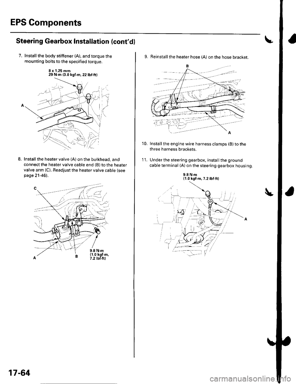
7. Installthe body stiffener (A), and torque the
mounting bolts to the specified torque.
8 x 1.25 mm29 N.m {3.0 kgf.m,22lbf.ftl
LInstall the heater valve (A) on the bulkhead, and
connect the heater valve cable end (B) to the heater
valve arm (C). Readjust the heater valve cable {seepage 21-46).
9.8 N.m(1.0 kgf m,7.2 tbf.ftl
L-t ,:.i.t'
17-64
9. Reinstall the heater hose (A) on the hose bracket.
Install the engine wire harness clamps (B) to the
three harness brackets.
Under the steering gearbox, install the ground
cable terminal (A) on the steering gearbox housing.
10.
'I t.
9.8 N.m{1.0 kgf.m, 7.2lbf.ft)
Page 556 of 1139
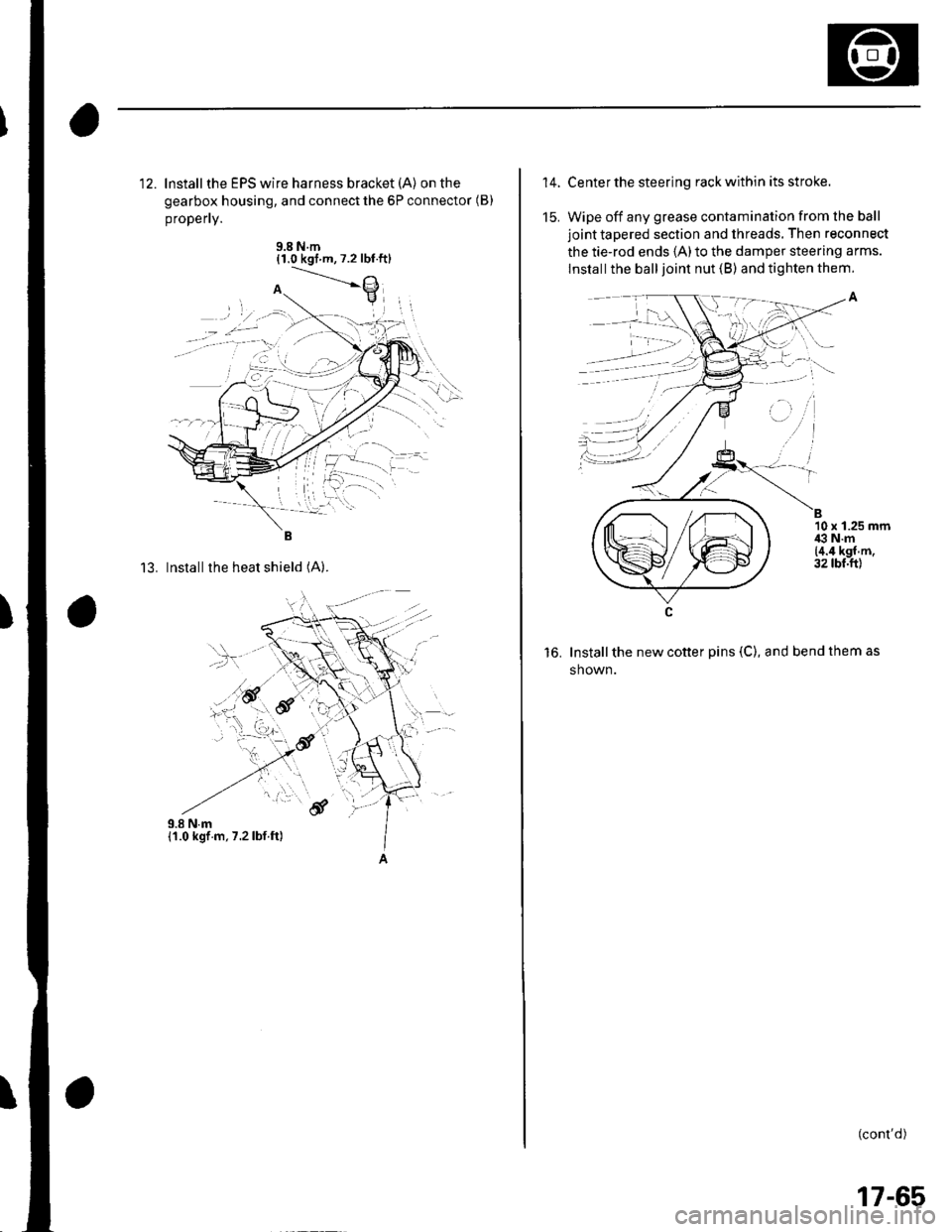
12. lnstallthe EPS wire harness bracket (A) on the
gearbox housing, and connect the 6P connector (B)
propefly.
9.8 N.m{1.0 kgt m,7.2 lbt.ftl
13. Installthe heat shield (A).
,.!,..''6f
14.
15.
Center the steering rack within its stroke.
Wipe off any grease contamination from lhe ball
joint tapered section and threads. Then reconnect
the tie-rod ends 1A)to the damper steering arms.
lnstall the ball joint nut (B) and tighten them.
Install the new cotter pins (C), and bend them as
shown.
(cont'd)
B10 x 1.25 mmi€ N.m{4.4 kgf.m.32 tbt.ftl
to.
, -', ''l
:1)
17-65
Page 557 of 1139
EPS Components
4
17.
18.
Steering Gearbox Installation (cont'dl
Install the motor on the steering gearbox (see page
17-49).
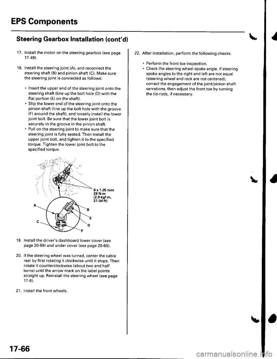
lnstall the steering joint (A). and reconnect the
steering shaft (B) and pinion shaft (C). Make sure
the steering joint is connected as follows:
. Insertthe upperend of thesteering jointontothe
steering shaft (line up the bolt hole (D) with the
flat portion (E) on the shaft).. Slip the lower end of the steering joint onto thepinion shaft (line up the bolt hole with the groove
(F) around the shaft), and loosely installthe lowerjoint bolt. Be sure that the lower joint bolt is
securely in the groove in the pinion shaft.. Pull on the steering joint to make sure that the
steering joint is fully seated. Then install the
upper joint bolt, and tighten it to the specified
torque. Tighten the lower joint bolt to the
specified torque.
8 x '1.25 mm28 N.m{2.9 kgf.m,21 tbt.ft)
19.
20.
Installthe driver's dashboard lower cover (see
page 20-59) and under cover (see page 20-60).
lf the steering wheel was turned, center the cable
reel by first rotating it clockwise until it stops. Then
rotate it counterclockwise (about two and half
turns) untilthe arrow mark on the label points
straight up. Reinstall the steering wheel (see page
17 -8).
Install the front wheels.)1
17-66
22. After installation, perform the following checks.
. Perform the front toe inspection.. Check the steering wheel spokeangle. lfsteering
spoke angles to the right and left are not equal(steering wheel and rack are not centered),
correct the engagement of the joinvpinion shaft
serrations, then adjust the front toe by turning
the tie-rods, if necessarv.
\
Page 558 of 1139
EPS Control Unit Removal/
Installation
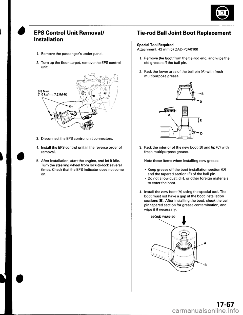
1. Remove the passenger's under panel.
2. Turn up the floor carpel, remove lhe EPS control
untr.
Disconnect the EPS control unit connectors.
lnstallthe EPS control unit in the reverse order of
removal.
After installation, start the engine, and let it idle.
Turn the steering wheelfrom lock-to-lock several
times. Check that the EPS indicator does not come
on.
3.
E
Tie-rod Ball Joint Boot Replacement
Special Tool Required
Attachment, 42 mm 07OAD-P0A0100
l. Remove the boot from the tie-rod end, and wipe the
old grease off the ball pin.
2. Pack the lower area of the ball pin(A)wilhfresh
mulr purpose grease.
3. Pack the interior of the new boot (B) and lip (C) with
fresh multipurpose grease.
Note these items when installing new grease;
. Keep grease offthe boot installation section (D)
and the tapered section (E) of the ball pin.
. Do not allow dust, dirt, or other foreign materials
to enter the boot.
4. Installthe new boot (A) using the specialtool. The
boot must not have a gap at the boot installation
sections (B). After installing the boot. check the ball
pin tapered section for grease contamination, and
wipe it if necessary.
07(lAD-P0A0100
*-4
r/ \-,d______i.l+_D
-6rA
17-67
Page 559 of 1139
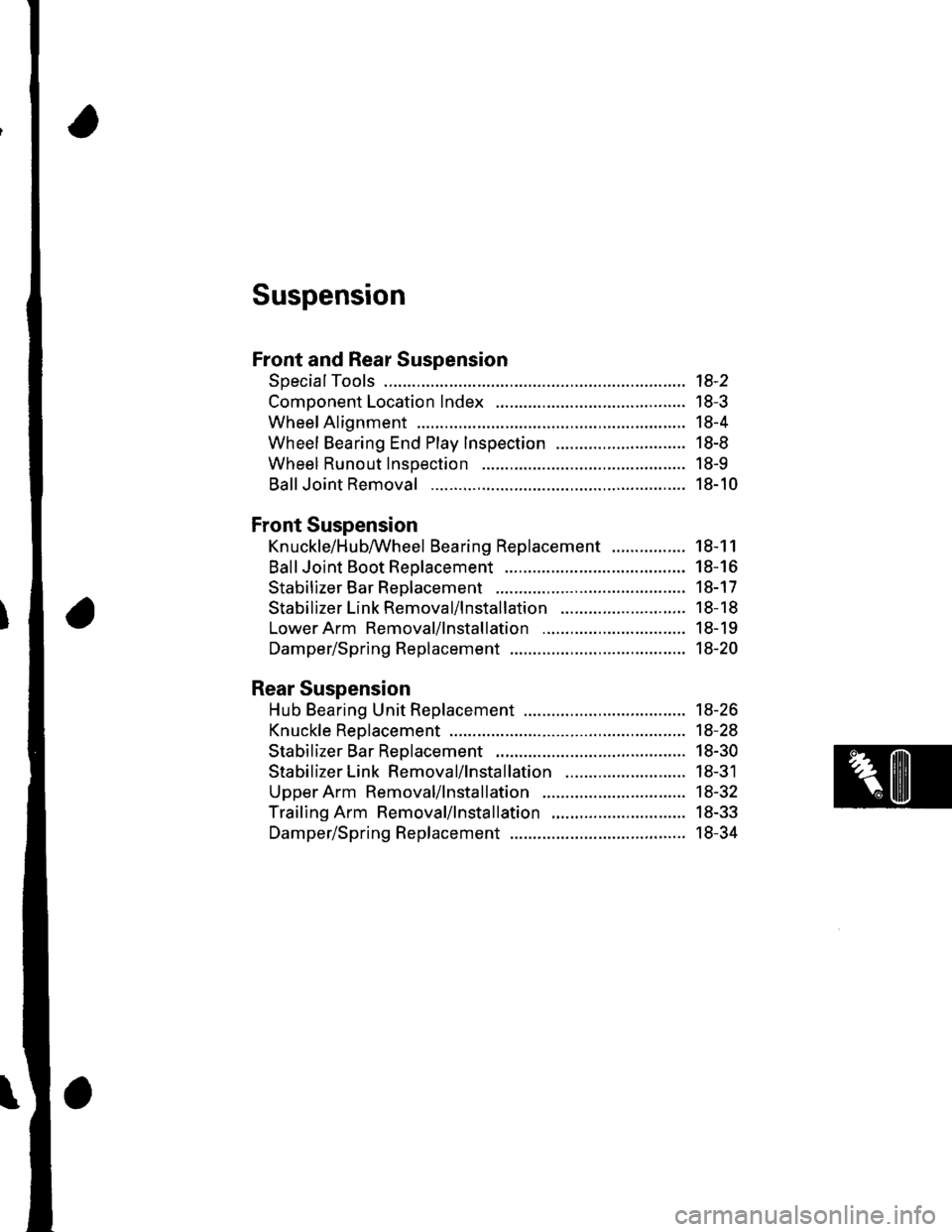
Suspension
Front and Rear Suspension
SpecialTools ............. 18-2
Component Location Index ......................................... 18-3
Wheel Alignment ..................... ........... 18-4
Wheel Bearing End Play Inspection ............................ 18-8
Wheel Runout Inspection .................. 18-9
Ball Joint Removal ... 18-10
Front Suspension
Kn uckle/H u bAVheel Bearing Replacement
Ball Joint Boot Reolacement ..................
Stabilizer Bar Rep|acement ....................
Stabilizer Link Removal/lnstallation
LowerArm Removal/lnstallation ...............
Damper/Spring Replacement
Rear Suspension
Hub Bearing Unit Replacement .....................
Knuckle Reolacement
Stabilizer Bar Replacement ....................
Stabilizer Link Removal/lnstallation ..........................
Upper Arm Removal/lnstallation ...............
Trailing Arm Removal/lnstallation
Damper/Spring Replacement
18-1 1
18-16
18-17
18-18
18-19
18-20
18-26
18-28
18-30
18-31
18-32
18-33
18-34
Page 560 of 1139
![HONDA CIVIC 2003 7.G Workshop Manual Front and Rear Suspension
SpecialTools
o
[]
o
o
a6,l@
I
Ref.No.Tool NumberDescriptionotv
o
@
o
G)
07GAF-SE00100
07MAC-S100200
07746-0010500
07749-0010000
07965-SA50500
07965-SD90100
Hub Dis/Assembly T HONDA CIVIC 2003 7.G Workshop Manual Front and Rear Suspension
SpecialTools
o
[]
o
o
a6,l@
I
Ref.No.Tool NumberDescriptionotv
o
@
o
G)
07GAF-SE00100
07MAC-S100200
07746-0010500
07749-0010000
07965-SA50500
07965-SD90100
Hub Dis/Assembly T](/img/13/5744/w960_5744-559.png)
Front and Rear Suspension
SpecialTools
o
[]
o
o
a6,l@
I
Ref.No.Tool NumberDescriptionotv
o
@
o
G)
07GAF-SE00100
07MAC-S100200
07746-0010500
07749-0010000
07965-SA50500
07965-SD90100
Hub Dis/Assembly Tool
Ball Joint Remover, 28 mm
Attachment, 62 x 68 mm
Driver
Front Hub Dis/Assembly Tool
Support Base
18-2