HONDA CIVIC 2003 7.G Workshop Manual
Manufacturer: HONDA, Model Year: 2003, Model line: CIVIC, Model: HONDA CIVIC 2003 7.GPages: 1139, PDF Size: 28.19 MB
Page 591 of 1139
3.
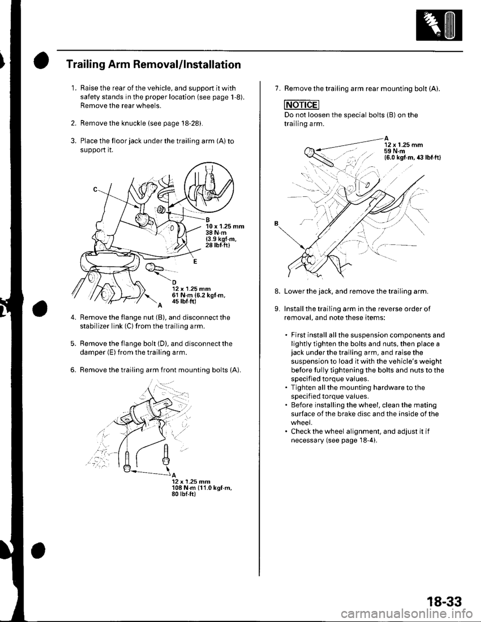
Trailing Arm Removal/lnstallation
1.Raise the rear of the vehicle, and suppon it with
safety stands in the proper location (see page 1,8).
Remove the rear wheels.
Remove the knuckle (see page 18-28).
Place the floor jack under the trailing arm (A) to
support it.
B10 x 1.25 mm38Nm(3.9 kgl.m,28 tbf.ftl
12 x 1.25 mm61 N m (6.2 kgt m.
A 4s tbf,ft)
Remove the flange nut (B), and disconnect the
stabilizer link (C) from the trailing arm.
Remove the flange bolt {D), and disconnect the
damper (E) from the trailing arm.
Remove the trailing arm front mounting bolts (A).
A12 x 1.25 Jnm108 N.m {11.0 kgt.m,80 tbf.ft)
,'a':r -
7. Remove the trailing arm rear mounting bolt (A).
Do not loosen the special bolts (B) on the
trailing arm.
A12 x 1.25 mm59 N.m
-----\':,'.ttg
'.,--1..-r.':1
Lower the jack, and remove the trailing arm.
Install the trailing arm in the reverse order of
removal, and note these items:
. First install allthe suspension components and
lightly tlghten the bolts and nuts, then place ajack under the trailing arm, and raise the
suspension to load it with the vehicle's weight
before fully tightening the bolts and nuts to the
specified torque values.. Tighten allthe mounting hardware to the
specif ied torque values.. Before installing the wheel, clean the mating
surface of the brake disc and the inside of the
wneei.. Check the wheel alignment, and adjust it if
necessary (see page'18-4).
8.
9.
18-33
Page 592 of 1139
Rear Suspension
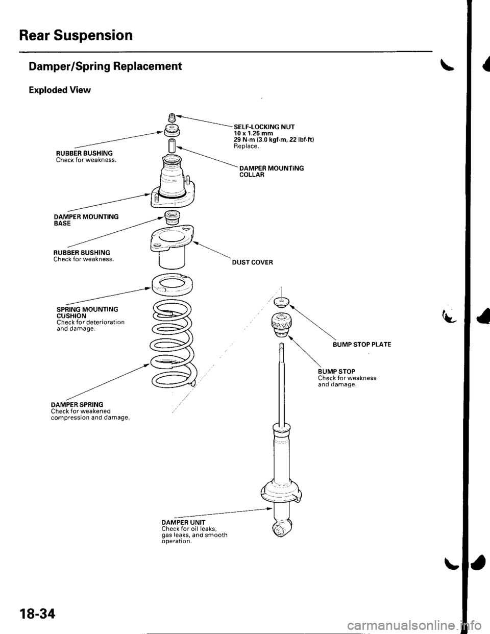
IDamper/Spring Replacement
Exploded View
DAMPER SPRINGCheck for weakenedcompression and damage.
9-----.---.-.I€tI -= SELF-LoCK|NG NUTt=J 10 x 1.25 mm29 N m {3.0 kgf.m,22 lbf.ft}Replace.
DAMPER MOUNlINGCOLLAR
DUST COVER
-t-
9...
r€) \qnJ/ \EZ\\
n BUMP sroP PLArE
lt \
/t \BUMP STOPCheck tor weaknessand damage.
OAMPER UNITCheck for oil leaks,gas leaks, and smoothoperation,
18-34
Page 593 of 1139
Removal
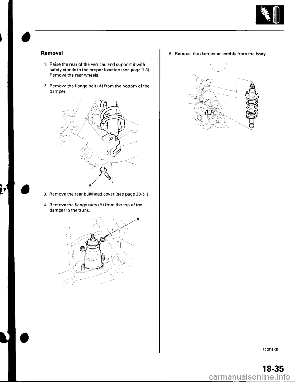
1. Raise the rear of the vehicle. and support it with
safety stands in the proper location (see page 1-8).
Remove the rear wheels.
2. Remove the flange bolt {A) from the bottom of the
damper.
Remove the rear bulkhead cover (see page 20-51).
Remove the flange nuts (A) from the top of the
damper in the trunk.
3.
5. Remove the damper assembly from the body.
i
(cont d)
18-35
Page 594 of 1139
Rear Suspension
Damper/Spring Replacement (cont'dl
Disassembly/lnspection
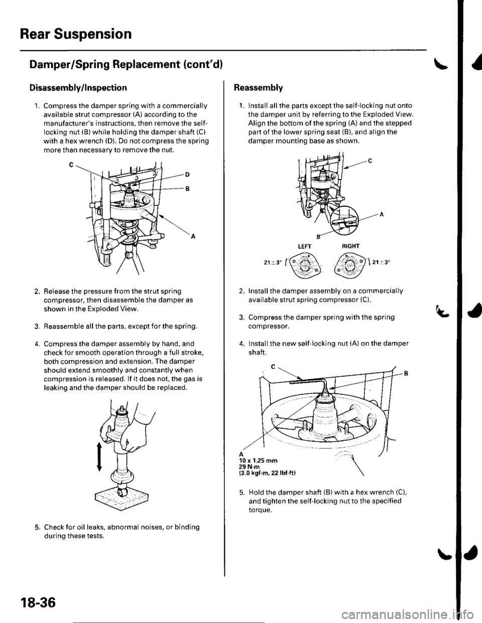
1. Compress the damper spring with a commercially
available strut compressor (A) according to the
manufacturer's instructions. then remove the self-
locking nut (B)while holding the damper shaft (C)
with a hex wrench (D). Do not compress the spring
more than necessarv to remove the nut.
Release the pressure from the strut spring
compressor, then disassemble the damper as
shown ln the Exploded View.
Reassemble all the pans, except for the spring.
Compress the damper assembly by hand, and
check for smooth operation through a full stroke,
both compression and extension. The damper
should extend smoothly and constantly when
compression is released. lf it does not, the gas is
leaking and the damper should be replaced.
?
4.
Check for oil leaks, abnormal noises, or binding
during these tests.
18-36
Reassembly
1. Install allthe partsexceptthe self-locking nutonto
the damper unit by referring to the Exploded View.
Align the bottom of the spring {A} and the stepped
part of the lower spring seat (B), and align the
damper mounting base as shown,
,, '161 7fi)1,, "
\3P qY/
Installthe damper assembly on a commercially
available strut spring compressor (C).
Compress the damper spring with the spring
compressor.
Installthe new self'locking nut (A) on the damper
shaft.
10 x 1.25 mm29Nm(3.0 kgt m,22 lbt.ft)
5. Hold the damper shaft {B) with a hex wrench (C),
and tighten the self-locking nut to the specified
torque.
Page 595 of 1139
D
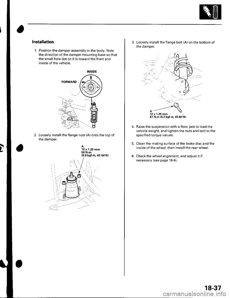
Installation
1. Position the damper assembly in the body. Note
the direction of the damper mounting base so that
the small hole dot on it is toward the front and
inside of the vehicle.
Loosely install the flange nuts (A) onto the top of
the damper,
A10 x 1.25 mm59 N.m16.0 kgt.m, ia lbt ft)
3. Loosely installthe flange bolt (A) on the bottom of
the damper.
12x 1.25 mm61 N m {6.2 kgf.m. 45 lbf.ft)
Raise the suspension with a floor jack to load the
vehicle weight, and tighten the nuts and bolt to the
specified torque values.
Clean the mating surface ofthe brake disc and the
inside of the wheel, then install the rear wheel.
Check the wheel alignment, and adjust it if
necessary (see page 18-4).
18-37
Page 596 of 1139
Brakes
Conventional Brake Components
Special Tools ... ..... ... l9-2
Component Location Index ......................................... 19-3
Brake System Inspection and
Tests ............... .......... 19-4
Brake Pedal and Brake Pedal Position Switch
Adjustment .............. 19-6
Parking Brake Check and
Adjustment .............. 19-7
Brake System Bleeding ...................... 19-8
Brake System Indicator Circuit
Diagram ................... 19-9
Parking Brake Switch Test ................. 19-10
Brake Fluid Level Switch Test ...................................... 19-10
Front Brake Pads lnsoection and
Replacement ........... 19-11
Front Brake Disc Inspection ............... 19-13
Front Brake Calioer Overhaul ...................................... 19-14
Master Cylinder Replacement ........... 19-15
Master Cylinder Inspection ................ 19-16
Brake Booster
Pushrod Clearance Adjustment ................................ 19-16
Brake BoosterTest ................... .......... 19-18
Brake Booster Reolacement .............. 19-19
Rear Brake Pads Inspection and
Reolacement ........... 19-20
Rear Brake Disc Inspection ................ 19-22
Rear Brake Caliper Overhaul ....................................... 19-23
Brake Hoses and Lines Insoection .... 19-24
Brake Hose Reolacement ................... 19-25
Parking Brake Cable Replacement .............................. 19-26
ABS (Anti-lock Brake System)
Gomponents ... 19-29
Page 597 of 1139
Conventional Brake Components
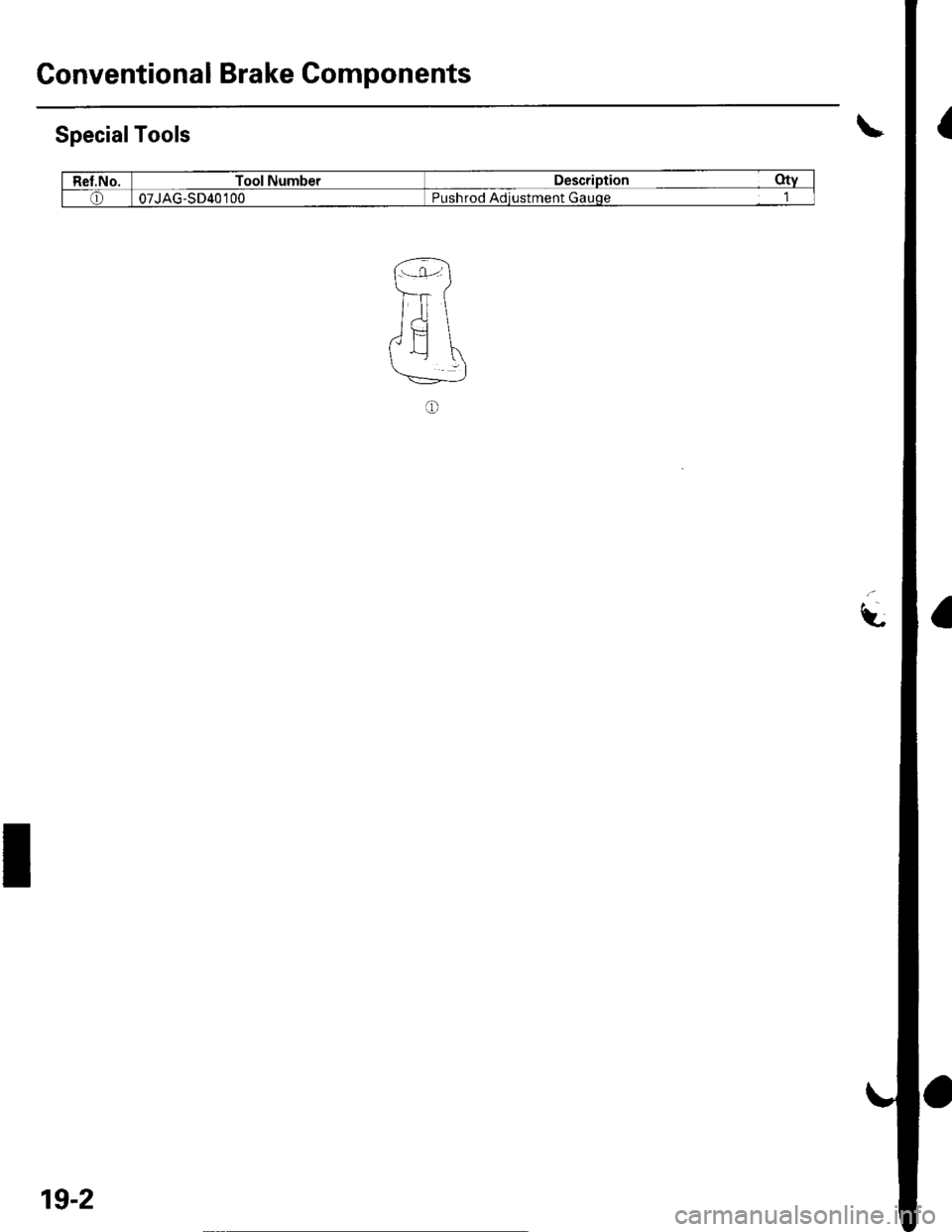
SpecialTools
Ref.No.Tool NumberDescriDtion Qty
o07JAG-SD40 100Pushrod Adiustment Gauoe 1
I
19-2
Page 598 of 1139
Component Location Index
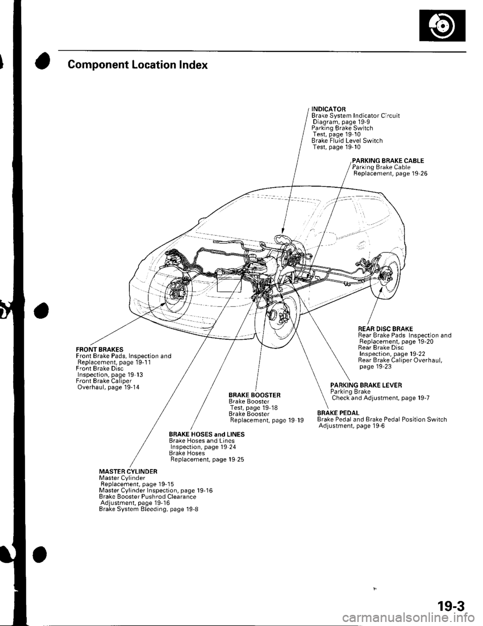
FRONT BRAKESFront Brake Pads, Inspection andReplacement, page 19-1 1Front Brake DiscInspection, page 19'13Front Brake CaliperOverhaul, page 19-14
INDICATORBrake System Indicator CircuitDiagram, page 19-9Parking Brake SwitchTest, page 19 10Brake Fluid Level SwitchTest, page 19-10
BRAKE CABLE
BRAKE BOOSTERBrake BoosterTest, page 19-18Brake EoosterReplacement, page 19 19
Parking Brake CableReplacement, page 19 26
REAR DISC BRAKERear Brake Pads Inspection andReplacement, page l9-20Rear Brake DiscInspection, page 19'22Rear Brake Caliper Overhaul,page 19'23
PARKING BRAKE LEVERParkino BrakeCheck and Adjustment, page 19-7
BRAKE PEDALBrake Pedal and Erake Pedal Position SwitchAdjustment, page l9-6
BRAKE HOSES and LINESBrake Hoses and LinesInspection, page 19 24Brake HosesReplacement, page 19 25
MASTER CYLINDERMaster CylinderFl6^1.^6m6nr ^2^o 1O-18Master Cylinder Inspection, page 19-16Brake Booster Pushrod ClearanceAdjustment, page'19-16Brake System Bleeding, page 19-8
19-3
Page 599 of 1139
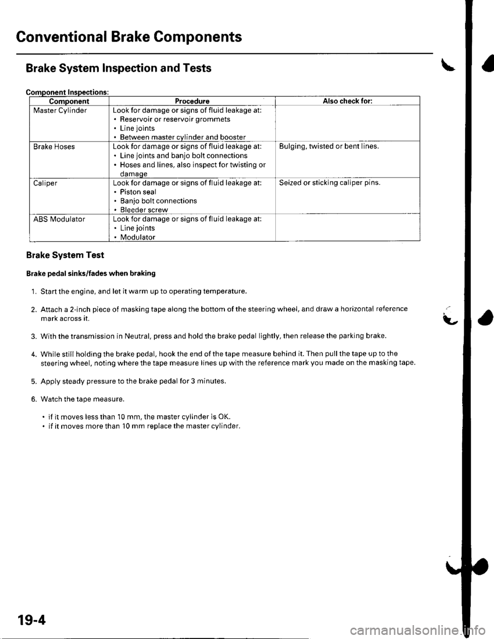
Gonventional Brake Components
ComponentProcedureAlso check for:
l\4aster CylinderLook for damage or signs of fluid leakage at;. Reservoir or reservoir grommets
. Line joints
. Between master cvlinder and booster
Brake HosesLook for damage or signs of fluid leakage at:. Line joints and banjo bolt connections. Hoses and lines. also inspect for twisting or
damaqe
Bulging, twisted or bent lines.
CaliperLook for damage or signs of fluid leakage at:. Piston seal. Banjo bolt connections. Bleeder screw
Seized or sticking caliper pins.
ABS l\ilodulatorLook for damage or signs of fluid leakage at:. Line joints
. Modulator
Brake System Inspection and Tests
Brake System Test
Brake pedal sinks/fades when braking
1. Start the engine, and let it warm up to operating temperature.
2. Attach a 2-inch pieceof masking tape along the bottom of the steering wheel, and draw a horizontal reference
mark across it.
With the transmission in Neutral, press and hold the brake pedal lightly, then release the parking brake.
While still holding the brake pedal, hook the end of the tape measure behind it. Then pull the tape up to the
steering wheel, noting where the tape measure lines up with the reference mark you made on the masking tape.
Apply steady pressure to the brake pedal for 3 minutes.
Watch the tape measure.
. if it moves less than 10 mm, the master cylinder is OK.
. if it moves more than 10 mm replace the master cylinder.
t-
3.
5.
6.
19-4
Page 600 of 1139
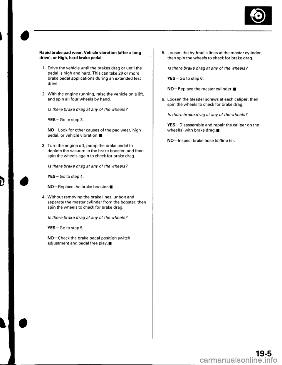
Rapid brake pad wear. Vehicle vibration {after a long
drivel, or High, hard brake pedal
1. Drive the vehicle until the brakes drag or untilthe
pedal is high and hard. This can take 20 or more
brake pedal applications during an extended test
drive.
2. With the engine running, raise the vehicle on a lift,
and spin all four wheels by hand.
ls there btake drag at any of the wheels?
YES Go to step 3.
NO Look for other causes of the pad wear, high
pedal, or vehicle vibration.I
3. Turn the engine off, pump the brake pedal to
deplete the vacuum in the brake booster, and then
spin the wheels again to check for brake drag.
ls therc brake dtag at any ot the wheels?
YES-Go to step 4.
NO Replace the brake booster.I
4. Without removing the brake lines, unbolt and
separate the master cylinder from the booster, then
spin the wheels lo check for brake drag.
ls there btake drag at any of the wheels?
YES Go to step 5,
NO-Check the brake pedal position switch
adjustment and pedal free play.I
5. Loosen the hydraulic lines at the master cylinder,
then spin the wheels to check for brake drag.
ls there brake drag at any of the wheels?
YES Go to step 6.
NO- Replace the master cylinder.l
6. Loosen the bleeder screws at each caliper, then
spin the wheels to check for brake drag.
Is there brake drag at any of the wheels?
YES Disassemble and repair the caliper on the
wheel(s) with brake drag.l
NO Inspect brake hose (s)/line (s).
19-5