check engine HONDA CIVIC 2003 7.G Repair Manual
[x] Cancel search | Manufacturer: HONDA, Model Year: 2003, Model line: CIVIC, Model: HONDA CIVIC 2003 7.GPages: 1139, PDF Size: 28.19 MB
Page 242 of 1139
Evaporative Emission (EVAPI Control
System
Refer to the System Diagram to see the functional
layout of the system.
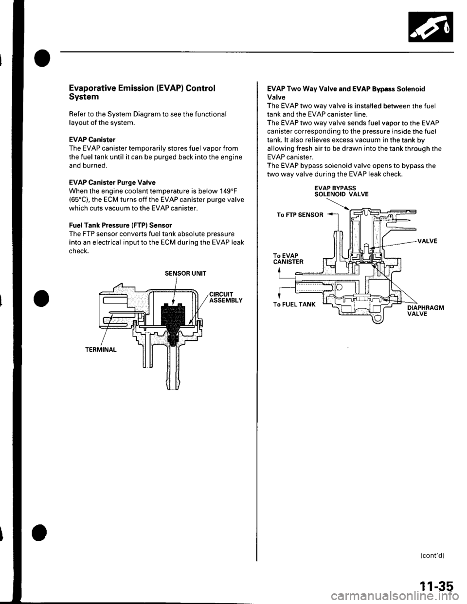
EVAP Canister
The EVAP canister temporarily stores fuel vapor from
the fuel tank until it can be purged back into the engine
and burned.
EVAP Canister Purge Valve
When the engine coolant temperatu re is below 149'F(65'C), the ECM turns off the EVAP canister purge valve
which cuts vacuum to the EVAP canister.
FuelTank Pressure (FTP) Sensor
The FTP sensor converts fueltank absolute pressure
into an electrical inputto the ECM during the EVAP leak
cnecK.
SENSOR UNIT
EVAP Two Way Valve and EVAP Eyp8s Solenoid
Valve
The EVAP two way valve is installed between the fuel
tank and the EVAP canister line.
The EVAP two way valve sends fuel vapor to the EVAP
canister corresponding to the pressure inside the tuel
tank. lt also relieves excess vacuum in the tank by
allowing fresh air to be drawn into the tank through the
EVAP canister.
The EVAP bypass solenoid valve opens to bypass the
two way valve during the EVAP leak check.
EVAP BYPASSSOLENOID VALVE
VALVE
(cont'd)
To FUEL TANK
11-35
Page 253 of 1139
Fuel and Emissions Systems
How to Set Readiness Codes
Malfunction lndicator Lamp (MlL) Indication
(ln relation to Readiness Codesl
The vehicle has certain "readiness codes" that are part
of the on-board diagnostics for the emissions systems.
lf the vehicle's battery has been disconnected or gone
dead, if the DTCS have been cleared, or if the ECM has
been reset, these codes are set to incomplete. In some
states, part of the emission testing is to make su re these
codes are set to complete. lf all of them are not set to
complete, the vehicle may fail the emission test, or the
test cannot be finished.
To check ifthe readiness codes are complete, turn the
ignition switch ON (ll), but do not start the engine. The
MIL will come on for 15 20 seconds. lf it then goes off,
the readiness codes are complete. lf it blinks several
times, one or more readiness codes are not complete.
To set readlness codes from incomplete to complete.
do the procedure for the appropriate code.
11-46
L
Catalytic Converter Monitor and Readiness
Code
NOTE:. Do not turn the ignition switch off during the
procedure.
. All readiness codes are cleared when the battery is
disconnected or when the ECM is cleared with the
OBD ll scan tool or Honda PG lvl Tester.. Low ambient temperatures or excessive slop-and-go
traffic may increase the drive time needed to switch
the readiness code from incomplete to complete.' The readiness code will not switch to com Dlete until
all the enable criteria are met.. lf a fault in the secondary HO2S system caused the
MIL to come on. the readiness code cannot be set to
comDlete until vou correct the fault.
Enable Criteria. ECT at 158"F (70'C) or higher.. Intake air temperature (lAT) at 20"F (-7'C) or higher.. Vehicle speed is steady, and vehicle speed sensor
(VSS) reads more then 25 mph (13km/h).
Procedure
1. Connect the scan tool to the vehicle's data link \
connector (DLCi, and bring up the tool's generic \"
OBD ll mode.
Start the engine.
Test-drive the vehicle under stop-and-go conditions
with short periods of steady cruise. After about
5 miles (3 km), the readiness code should switch
from incomplete to complete.
lf the readiness code is still set to incomplete, check
for a temporary DTC. lf there is no DTC, one or
more of the enable crlteria were probably not met;
2.
3.
Page 254 of 1139
Evaporative Emissions (EVAP) Control
System Monitor and Readiness code
NOTE:
All readiness code are cleared when the batterV is
disconnected or when the ECM is cleared with the
OBD ll scan tool or Honda PGM Tester.
The enable criteria must be repeated if the intake air
temperature (lAT) drops lower than 36'F (20"C) from
its value at engine $an up.
Enable Criteria
At engine start up, ECT and IAT are higher than 32'F(0"C) , but lower than 95'F (35"C).
At engine start up, the ECT and IAT are within 12'F(7'C) of each other.
Procedure
1. Connect the scan tool to the vehicle's data link
connector (DLC), and bring up the tool's generic
OBD ll mode.
2. Start the engine.
3. Test-drive the vehicle under stop-and-go conditions
with short periods of steady cruise. After about
2.5 miles (1.6 km), the readiness code should
switch f rom incomplete to complete.
4. lf the readinesscode isstill setto incomplete, check
for a temporary DTC. lf there is no DTC, one or
more of the enable criteria were probably not met;
repeat the procedure.
Air Fuel Ratio (A/Fl Sensor Monitor and
Readiness Code
NOTE:. Do not turn the ignition switch off during the
orocedure.. All readiness codes are cleared when the baftery is
disconnected or when the ECM is cleared with the
OBD ll scan tool or Honda PGM Tester.
Enable Criteria
ECT at 140'F (60"C) or higher.
Procedure
1. Connect the scan toolto the vehicle's data link
connector (DLC), and bring up the tool's generic
OBD ll mode.
2. Start the engine.
3. Test-drive the vehicle under stop-and-go conditions
with short periods of steady cruise. During the
drive, decelerate (wirh the throttle fully closed) for
5 seconds. After about 3.5 miles (2.2 km). the
readiness code should switch from incomDlete to
complete.
4. lfthereadinesscodeisstill set to incomplete, check
for a temporary DTC. lfthere is no DTC, the enable
criteria was probably not meU repeat the procedure.
Air/Fuel Ratio (A/Fl Sensor Heater Monitor
Readiness Code
NOTE; All readiness codes are cleared when the battery
is disconnected or when the ECM is cleared with the
OBD ll scan tool or Honda PGM Tester,
Procedure'1. Connect the scan tool to the vehicle's data link
connector {DLC), and bring up the tool's generic
OBD ll mode.
2. Start the engine, and let it idle for 1 minute. The
readiness code should switch from incomplete to
comDlete.
3. lf the readiness code is still set to incomplete, check
for a temporary DTC. lf there is no DTC, repeat theproceoure.
(cont'd)
11-47
Page 260 of 1139
DTC P0108: MAP Sensor Circuit High Voltage
'1. Start the engine. Hold the engine at 3,000 rpm with
no load (in neutral) until the radiator fan comes on,
then let it idle.
2. Check the MAP with the scan tool.
le about 101 kPa (780 nmHg, 30 in.Hg) ot highet,
or about 2.9 V or higher indicated?
YES Go to step 3.
NO-lntermittent failure, system is OK at this time.
Check for poor connections or loose terminals at
the MAP sensor and at the ECM.I
3. Turn the ignition switch OFF.
4. Disconnectthe MAP sensor 3P connector.
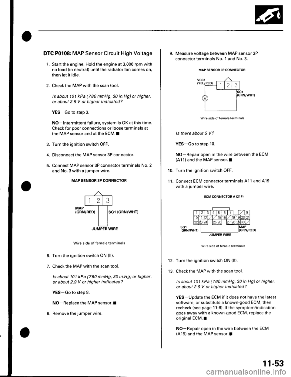
5, Connect MAP sensor 3P connector terminals No. 2
and No. 3 with a jumper wire.
MAP S€NSOR 3P CONNECTOR
MAP{GRN/REO}SG1 (GRN/WHTI
JUMPER WIRE
Wire side of female terminals
6. Turn the ignition switch ON (ll).
7. Check the MAP with the scan tool.
ls about 101 kPa (760 mmHg,30 in.Hg) ot higher,
or about 2.9 V or higher indicated?
YES-Go to step 8.
NO Replace the MAP sensor.I
8. Remove the jumper wire.
123
9. Measure voltage between MAP sensor 3P
connector terminals No. 1 and No. 3.
MAP SENSOR 3PCONNECTOF
vccl{YEL/RED) l,lo cll.l.rl
I lsct
d) l{GRN/wHrr
YIilll
Wire side of female lerminals
ls there about 5 V?
YES Go to step 10.
NO Repair open in the wire between the ECM
(A1 1 ) and the MAP sensor.I
Turn the ignition switch OFF.
Connect ECM connector terminals A11 and A19
with a jumper wire.
ECM CONNECTOR A {31PI
Wire side of fema e te.minals
Turn the ignition switch ON (ll).
Check the MAP with the scan tool.
ls about 101 kPa (760 mmHg, 30 in.Hg) or higher,
or about 2.9 V ot higher indicated?
YES Update the ECM if it does not have the lalest
software, or substitute a known-good ECM, lhen
recheck (see page 1 1-6). lf the symptom/indication
goes away with a known good ECM, replace the
original ECM.I
NO-Repair open in the wire betlveen the ECI\il
(A19) and the MAP sensor.I
10.
11.
JUMPER WIAE
11-53
Page 261 of 1139
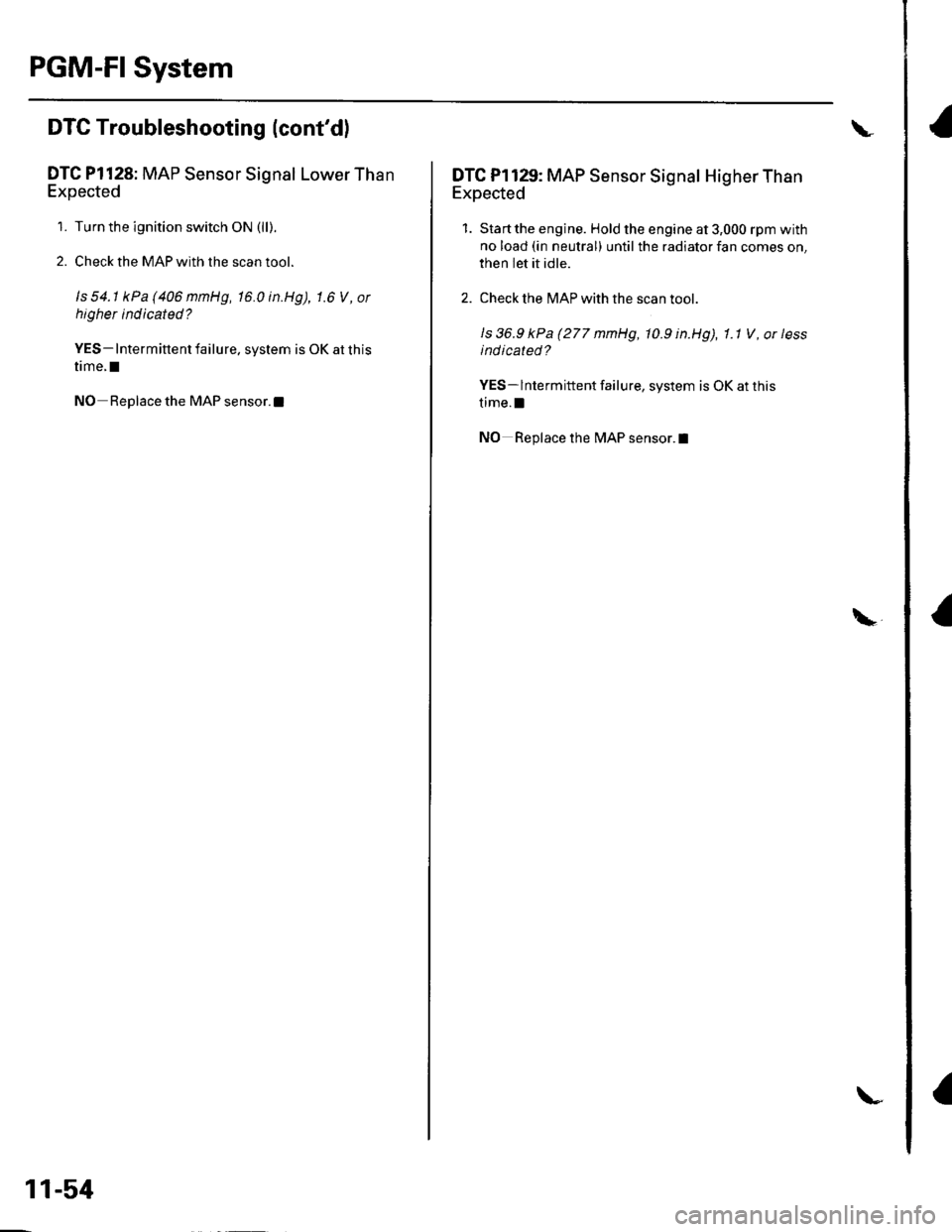
PGM-FI System
a
DTC Troubleshooting (cont'dl
DTC Pl128: MAP Sensor Signal Lower Than
Expected
1. Turn the ignition switch ON (ll).
2. Check the MAP with the scan tool.
ls 54.1 kPa(406mmHg, 16.0in.Hg), 1.6 V, or
higher indicated?
YES- Intermittent failure. system is OK at this
time.I
NO Replace the MAP sensor.l
11-54
\
\
DTC Pl129: MAP Sensor Signal Higher Than
Expected
1. Start the engine. Hold the engine at 3,000 rpm with
no load (in neutral) until the radiator fan comes on,
then Iet it idle.
2. Check the MAP with the scan toot.
ls 36.9 kPa (277 mmHg, 10.9 in.Hg), 1.1 V , or less
indicated?
YES- lntermittent failure, system is OK at this
time.l
NO Replace the MAP sensor.l
\
Page 262 of 1139
4.
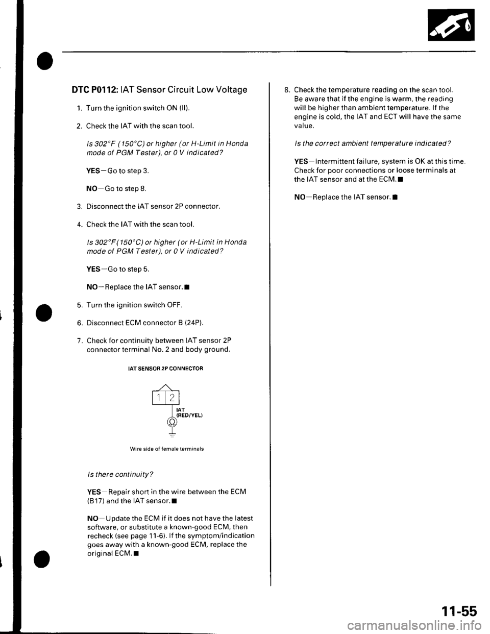
DTC P0112: IAT Sensor Circuit Low Voltage
1. Turn the ignition switch ON (ll).
2. Check the IAT with the scan tool.
ls 302'F (150'C) or highet (or H-Limit in Honda
node of PGM Tester), ot 0 V indicated?
VES-Go to step 3.
NO Go to step 8.
Disconnect the IAT sensor 2P connector.
Check the IAT with the scan tool.
ls 302'F(150'C)or higher (or H-Limit in Honda
mode of PGM Testet), ot 0 V indicated?
YES-Go to step 5.
NO- Replace the IAT sensor.I
Turn the ignition switch OFF.
Disconnect ECM connector B (24P).
Check for continuity between IAT sensor 2P
connector terminal No. 2 and body ground,
IAT SENSOR2P CONNECTOR
,^ ,lr 2lt-l-----Tr---IAT_t{RED/YELI
II
Wire side of female terminais
ls there continuity?
YES Repair shon in the wire between the ECM
(B'17) and the IAT sensor.l
NO Update the ECM if it does not have the latest
software, or substitute a known-good ECM, then
recheck (see page 11-6). lf the symptom/indication
goes away with a known-good ECM, replace the
original ECM.I
5.
6.
7.
8. Check the temperature reading on the scan tool.
Be aware that if the engine is warm, the reading
will be higher than ambient temperature. lI the
engine is cold, the IAT and ECT will have the same
va lue.
ls the correct ambient temperature indicated?
YES lntermittent failure, system is OK at this time
Check for poor connections or loose terminals at
the IAT sensor and at the ECM.I
NO Replace the IAT sensor.l
11-55
Page 264 of 1139
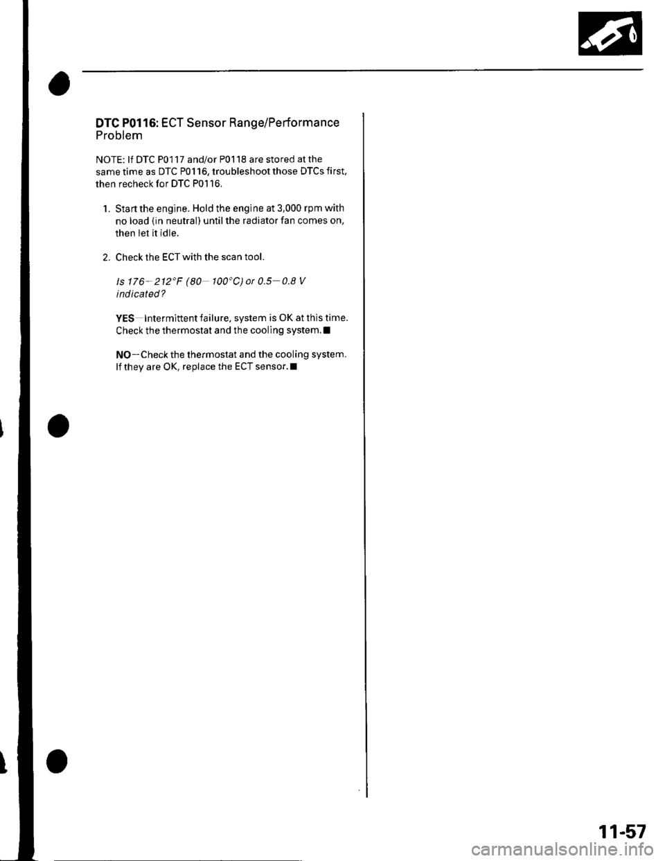
DTC P0116: ECT Sensor Range/Performance
Problem
NOTE: lf DTC P0117 and/or P0118 are stored at the
same time as DTC P0116, troubleshoot those DTCS first,
then recheck for DTC P0116,
1. Stanthe engine. Hold the engine at 3,000 rpm with
no load {in neutral) until the radiator fan comes on,
then let it idle.
2. Check the ECT with the scan tool.
ls 176- 212'F (80 100"C)or0.5 0.8V
indicated?
YES Intermittent failure. system is OK at this time.
Check the thermostat and the cooling system.l
NO-Checkthe thermostat and the cooling system.
lf they are OK, replace the ECT sensor.l
11-57
Page 271 of 1139
PGM-FI System
aDTG Troubleshootang (cont'dl
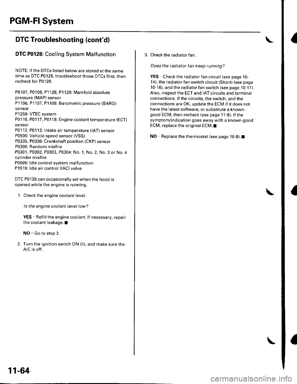
DTC P0128: Cooling System Malfunction
NOTE; lf the DTCS listed below are stored at the same
time as DTC P0128. troubleshoot those DTCS first, thenrecheck for P0128.
P0107, P0108, P1128, P1129: N4anifold absolutepressure (MAP) sensor
P] I06, P1 107, P1 108: Barometric pressure (BARO)
sensor
P1259: VTEC system
P01 16, P01 17, P01 18: Engine coolant temperature (ECT)
sensor
P01 12, P01 13: Intake air temperature (lAT) sensor
P0500: Vehicle speed sensor {VSS)P0335, P0336: Crankshaft position (CKP) sensor
P0300: Random misfire
P0301, P0302, P0303, P0304: No. 1, No. 2, No.3 or No.4
cylinder misfire
P0505: ldle control system malfunction
P1519: ldle air control (lAC)valve
DTC P0128 can occasionally set when the hood is
opened while the engine is running.
1. Check the engine coolant level
Is the engine coolant level low?
VES Refill the engine coolant. lf necessary, repair
the coolant leakage.l
NO Go to step 2.
2. Turn the ignition switch ON (ll), and make sure the
A,/C is off.
11-64
\
3. Check the radiator fan.
Does the tadiator fan keep running?
YES Checkthe rad iato r fan circuit (see page 10-
14), the radiator fan switch circuit (Short) (see page
10-'16), and the radiator fan switch (see page 10-17).
Also, inspect the ECT and IAT circuits and terminal
connections. lf the circuits, the switch, and the
connections are OK, update the ECI\4 if it does not
have the latest software. or substitute a known-good ECM, then recheck (see page 1 1-6). lf the
symptom/indication goes away with a known-good
ECM, replace the original ECM.I
NO Replace the thermostat (see page 10-8).1
Page 272 of 1139
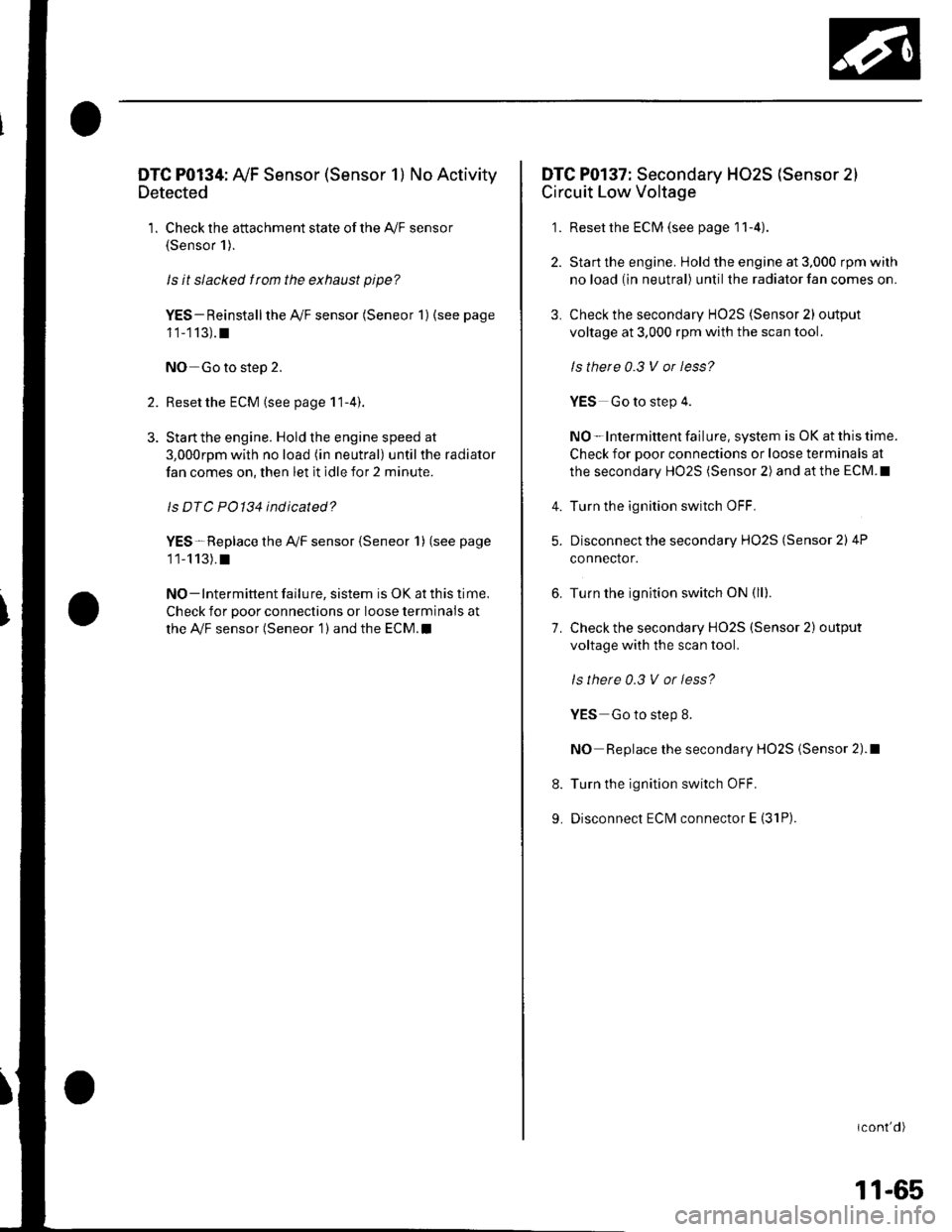
DTC P0134: Ay'F Sensor (Sensor 1) No Activity
Detected
1. Check the attachment state of the A,/F sensor(Sensor 1).
ls it slacked f rom the exhaust pipe?
YES- Reinstall the Ay'F sensor (Seneor 1) (see page
11-113).t
NO-Go to step 2.
2. Reset the ECM (see page 1 1-4).
3. Stan the engine. Hold the engine speed at
3,000rpm with no load (in neutral) until the radiator
fan comes on, then let it idle for 2 minute.
ls DTC PO134 indicated?
YES-Replace the Ay'F sensor {Seneor 1) (see page
11-113).t
NO - Intermittent failu re, sistem is OK at this time.
Check for poor connections or loose terminals at
the Ay'F sensor (Seneor 1 ) and the ECM.I
DTC P0137: Secondary HO2S (Sensor 2)
Circuit Low Voltage
1. Reset the ECM (see page I1-4)
2. Start the engine. Hold the engine at 3,000 rpm wilh
no load (in neutral) until the radiator fan comes on.
3. Check the secondary HO2S (Sensor 2) output
voltage at 3,000 rpm with the scan tool.
ls there 0.3 V or less?
YES Go to step 4.
NO-lntermittent failure, system is OK at this time.
Check for poor connections or loose terminals at
the secondary HO2S (Sensor 2) and at the ECM.I
Turn the ignition switch OFF.
Disconnect the secondary HO2S (Sensor 2) 4P
connector.
Turn the ignition switch ON (ll).
Check the secondary HO2S (Sensor 2) output
voltage with the scan tool.
ls there 0.3 V or less?
YES Go to step 8.
NO Replace the secondary HO2S (Sensor 2).1
Turn the ignition switch OFF.
Disconnect ECM connector E (31P).
icont'd)
4.
5.
6.
7.
8.
9.
11-65
Page 273 of 1139
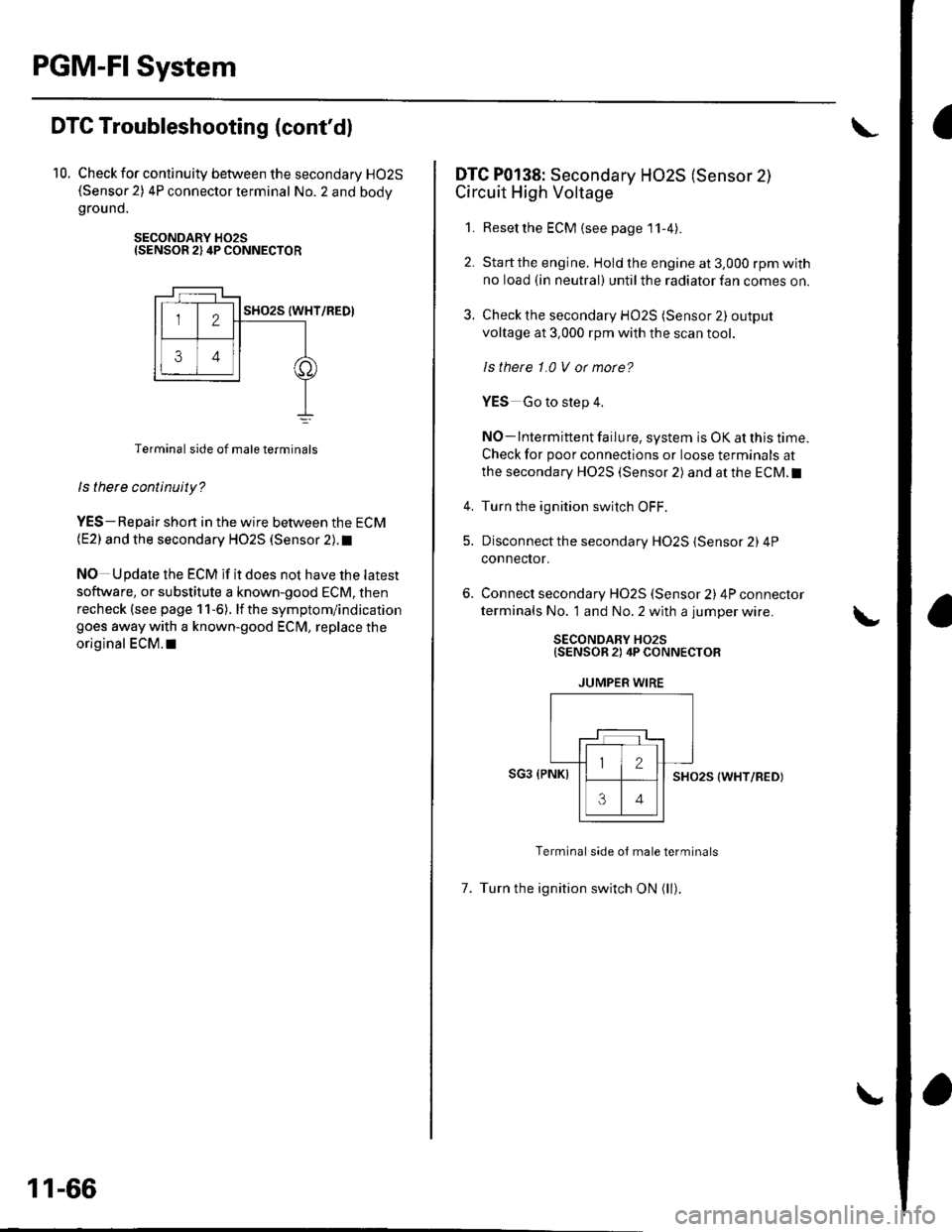
PGM-FISystem
aDTC Troubleshooting (cont'dl
10. Check for continuity between the secondary HO2S(Sensor 2) 4P connector terminal No. 2 and bodygrou nd.
SECONDARY H02SISENSOR 2) 4P CONNECTOR
Terminal side of male terminals
ls there continuity?
YES-Repair shon in the wire between the ECM(E2) and the secondary HO2S (Sensor 2). t
NO Update the ECM if it does not have the latest
software, or substitute a known-good ECM, then
recheck (see page 1 1-6). lf the symptom/indication
goes away with a known-good ECM, replace the
original ECM.I|
11-66
DTC P0138: Secondary HO2S (Sensor 2)
Circuit High Voltage
1. Resetthe ECM {see page'11-4).
2. Startthe engine. Hold the engine at 3,000 rpm with
no load (in neutral) until the radiator fan comes on.
3. Check the secondary HO2S (Sensor 2) output
voltage at 3,000 rpm with the scan tool.
ls thete 1.0 V or morc?
YES Go to step 4.
NO-lntermittent failure, system is OK at this time.
Check for poor connections or loose terminals at
the secondary HO2S (Sensor 2) and at the ECM.I
4. Turn the ignition switch OFF.
5. Disconnect the secondary HO2S (Sensor 2) 4P
connector.
Connect secondary H02S (Sensor 2) 4P connector
terminals No. 1 and No. 2 with a jumper wire.
SECONDARY HO2S{SENSOR 2) 4P CONNECTOR
JUMPER WIRE
SG3 (PNKISHO25 (WHT/RED)
Terminal side oJ male terminals
7. Turn the ignition switch ON (ll).