HONDA CIVIC 2003 7.G Workshop Manual
Manufacturer: HONDA, Model Year: 2003, Model line: CIVIC, Model: HONDA CIVIC 2003 7.GPages: 1139, PDF Size: 28.19 MB
Page 601 of 1139
Conventional Brake Components
Brake Pedaland Brake PedalPosition Switch Adjustment
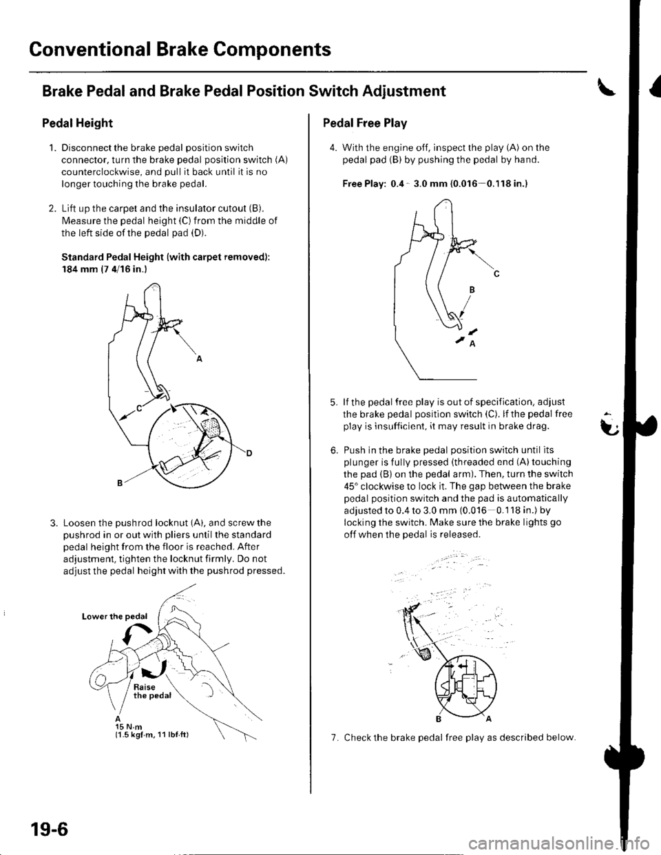
Pedal Height
1.Disconnect the brake pedal position switch
connector, turn the brake pedal position switch (A)
counterclockwise, and pull it back until it is no
longer touching the brake pedal.
Lift up the carpet and the insulator cutout (B).
l\4easure the pedal height (C) from the middle of
the left side of the pedal pad (D).
Standard Pedal Height (with carpet removed):
184 mm (7 4/16 in.)
Loosen the pushrod locknut (A), and screw the
pushrod in or out with pliers until the standard
pedal height from the floor is reached. After
adjustment, tighten the locknut firmly. Do not
adjust the pedal height with the pushrod pressed.
15 N.m(1.5 kgl m. 11 lbl ft)
19-6
7. Check the brake pedal free play as described below.
Pedal Free Play
4. With the engine off, inspect the play (A) on the
pedal pad (B) by pushing the pedal by hand.
Free Play: 0.4- 3.0 mm {0.016 0.'l18in.)
lf the pedal free play is out of specification, adjust
the brake pedal position switch (C). lf the pedal free
play is insufficient, it may result in brake drag.
Push in the brake oedal oosition switch until its
plunger is fully pressed (threaded end (A)touching
the pad (B) on the pedal arm). Then, turn the switch
45" clockwise to lock it. The gap between the brake
pedal position switch and the pad is automatically
adjusted to 0.4 to 3.0 mm (0.016 0.118 in.) by
locking the switch. Make sure the brake lights go
otf when the pedal is released.
t
6.
Page 602 of 1139
Parking Brake Check and Adiustment
Check
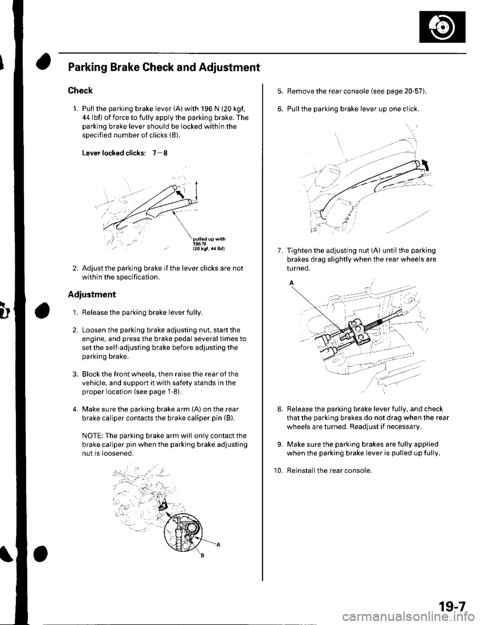
1. Pull the parking brake lever {A) with 196 N (20 kgf,
44 lbf) of force to fully apply the parking brake. The
parking brake lever should be locked within the
specified number of clicks (B).
Lever locked clicks: 7-8
- l2okqf, a4lbl)
2. Adjust the parking brake if the lever clicks are not
within the specification.
Adjustment
1. Release the parking brake lever fully.
Loosen the parking brake adjusting nut, start the
engine, and press the brake pedal several times to
set the self-adjusting brake before adjusting the
parking brake.
Block the front wheels, then raise the rear of the
vehicle, and support it with safety stands in the
proper location (see page 1-8).
Make sure the parking brake arm (A) on the rear
brake caliper contacts the brake caliper pin (B),
NOTE: The parking brake arm will only contact the
brake caliper pin when the parking brake adjusting
nut is loosened.
Remove the rear console {see page 20-57).
Pull the parking brake lever up one click,
7, Tighten the adjusting nut {A} until the parking
brakes drag slightly when the rear wheels are
tu rned.
A/
Release the parking brake lever fully, and check
that the parking brakes do not drag when the rear
wheels are turned. Readjust if necessary.
Make sure the parking brakes are fully applied
when the parking brake lever is pulled up fully.
Reinstall the rear console.
8.
9.
10.
19-7
Page 603 of 1139
Conventional Brake Components
Brake System Bleeding
NOTE:. Do not spill brake fluid on the vehicle; it may damage
the painU if brake fluid does contact the paint. wash it
off immediately with water.. The reservoir on the master cylinder must be at the
MAX (upper) level mark at the start of the bleeding
procedure and checked after bleeding each brake
caliper. Add fluid as required.. Do not reuse the drained fluid.. Always use Honda DOT 3 brake fluid. Non-Honda
brake fluid can cause corrosion and shorten the life of
the system.. Make sure no din or other foreign matter is allowed
to contaminate the brake fluid.
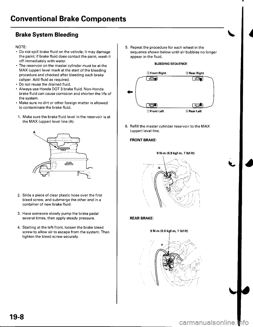
1. Make sure the brake fluid level in the reservoir is at
the MAX (upper) level line (A).
Slide a piece of clear plastic hose over the flrst
bleed screw, and submerge the other end in a
container of new brake fluid.
Have someone slowly pump the brake pedal
severaltimes, then apply steady pressure.
Starting at the left-front, loosen the brake bleed
screw to allow air to escape from the system. Then
tighten the bleed screw securely.
2.
19-8
5. ReDeatthe procedure for each wheel in the
sequence shown below until air bubbles no longer
appear in the fluid.
BLEEDING SEOUENCE:
OFront RightORe.r Right
O Front LeftORoar Loft
Refill the master cylinder reservoir to the MAX
{upper) level line.
FRONT BRAKE:
9 N.m 10.9 kgf.m,7 lbl.ft)
t-
REAR BRAKE:
9 N m 10.9 kgf.m, 7 lbf ft)
Page 604 of 1139
GRN/ORN
,tk ,o"","o ""o*.(b, 3s1E8,.""",,"
I oPEN,Leve,down
I-=:
I
A
YBtK
+csor
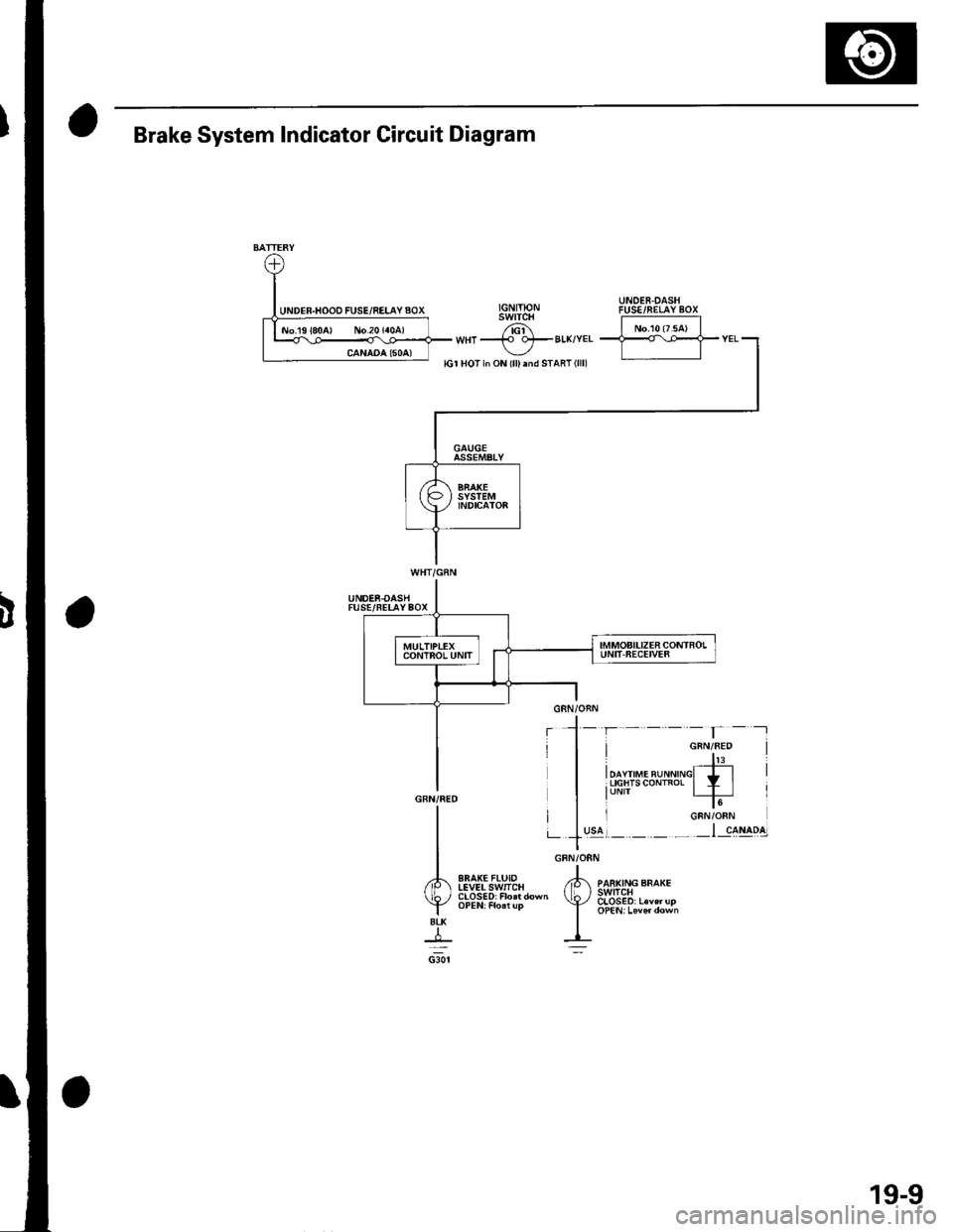
Brake System Indicator Circuit Diagram
UNDER.OASHFUSE/FELAYBOX
EBAK€FLUIDIEVELSwlICH
19-9
Page 605 of 1139
Conventional Brake Components
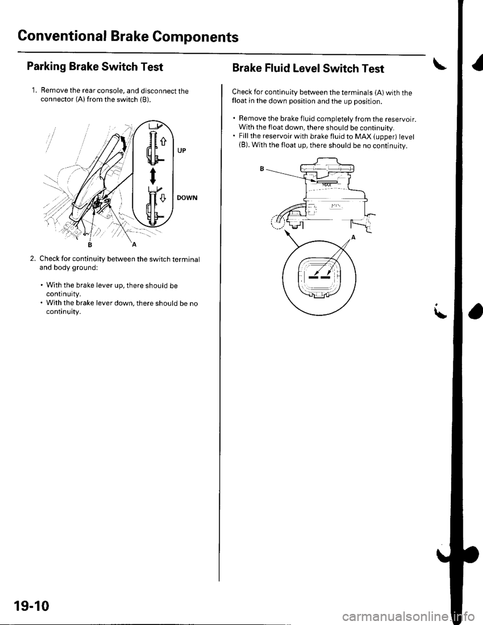
Parking Brake Switch Test
1. Remove the rear console, and disconnect theconnector (A)from the switch (B).
Check for continuity between the switch terminal
and body ground:
. With the brake lever up, there should be
continuity.. With the brake lever down, there should be no
continuity.
R
'dFu\!E!UF-
Y
19-10
Brake Fluid Level Switch Test
Check for continuity between the terminals (A) with thefloat in the down position and the up position.
. Remove the brake fluid completely from the reservoir.
With the float down, there should be continuity.. Fjllthe reservoir with brakefluidto MAX(upper) level(B). With the float up, there should be no continuity.
\
Page 606 of 1139
Frequent inhalation of brake pad dust, regardless of
material composition, could be hazardous to your
Front Brake Pads Inspection and Replacement
. Avoid breathing dust particles.
. Never use an air hose or brush to clean brake
assemblies. Use an OSHA-approved vacuum
cleaner.
lnspection
1. Raise the front of the vehicle, and support it with
safety stands in the proper location {see page 1'8).
Remove the front wheels.
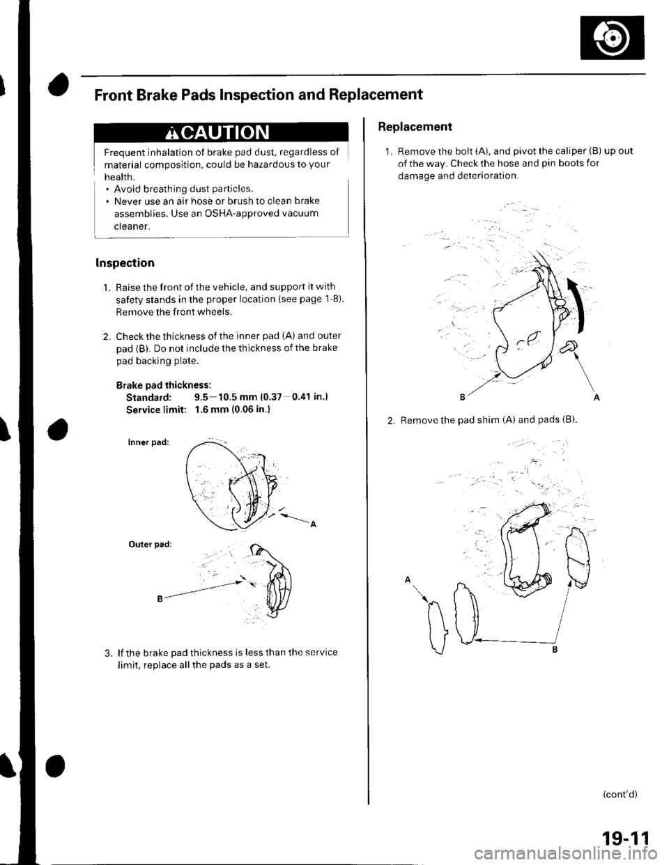
2. Check the thickness of the inner pad iA) and outer
pad {B). Do not include the thickness of the brake
pad backing plate.
Brake pad thickness:
Standard: 9.5 10.5 mm (0.37 0.41 in.l
Service limit: 1.6 mm (0.06 in.)
Inner pad:
Outer pad:
lf the brake Dad thickness is less than the service
limit, replace allthe pads as a set.
Replacement
1. Remove the bolt (A), and pivot the caliper (B) upout
of the way. Check the hose and pin boots for
damage and deterioration.
'..'
, .a
&
\
A
2. Remove the pad shim iA) andpads{B).
.^h v/
\ tJ I
v ."r------B
(cont'd)
19-11
Page 607 of 1139
Conventional Brake Gomponents
Front Brake Pads Inspection and Replacement (cont'dl
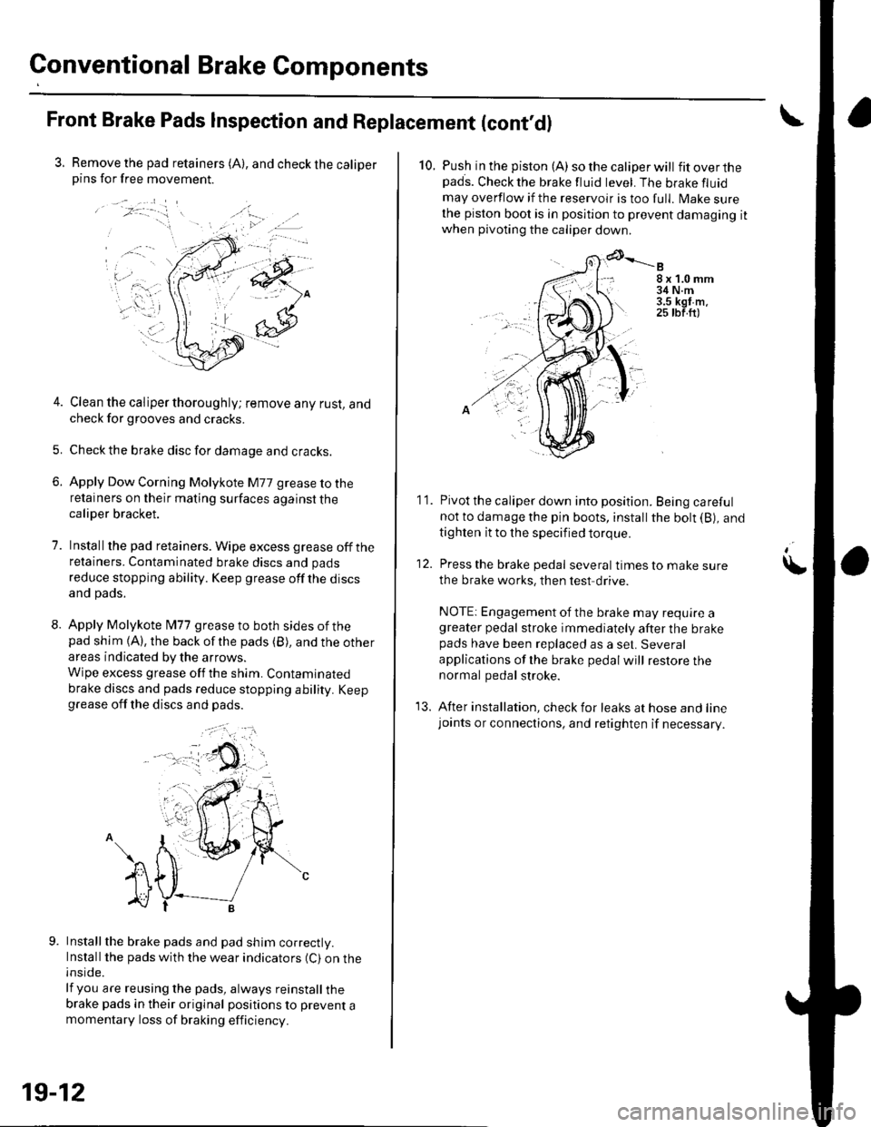
3. Remove the pad retainers (A), and check the caliperpins for free movement.
/:-."
t-... .,.';-iri.: '1=' r
.. a.-
4. Clean the caliper thoroughly; remove any rust, andcheck for grooves and cracks.
5. Checkthe brake disc for damage and cracks.
6. Apply Dow Corning Molykote M77 grease to theretainers on their mating surfaces against thecaliper bracket.
7. Installthe pad retainers. Wipe excess grease offtheretainers. Contaminated brake discs and pads
reduce stopping ability. Keep grease off the discsand pads.
8. Apply Molykote l\477 grease to both sides of thepad shim {A), the back ofthe pads (B), and the other
areas indicated by the arrows.
Wipe excess grease off the shim. Contaminated
brake discs and pads reduce stopping ability. Keepgrease off the discs and pads.
Installthe brake pads and pad shim correctly.Install the pads with the wear indicators (C) on theinside.
lf you are reusing the pads, always reinstall thebrake pads in their original positions to prevent amomentary loss of braking efficiency.
, a .).
19-12
10. Push in the piston (A) so the caliper will fitoverthepads. Check the brake fluid level. The brake fluid
may overflow if the reservoir is too full. lvlake surethe piston boot is in position to prevent damaging itwhen pivoting the caliper down
8x1.0mm34 N.m3.5 kgt m.25 tbf.ft)
11. Pivot the caliper down into position. Being carefulnot to damage the pin boots, install the bolt (B), and
tighten it to the specified torque.
12. Press the brake pedal several timestomakesure
the brake works, then test drive.
NOTE: Engagement of the brake may require agreater pedal stroke immediately after the brakepads have been replaced as a set. Several
applications of lhe brake pedal will restore thenormal pedal stroke.
13. After installation, check for leaks at hose and linejoants or connections, and retighten if necessary.
\
Page 608 of 1139
Front Brake Disc lnspection
Runout
1. Raise the front of the vehicle, and support it with
safety stands in the proper location (see page 1-8).
Remove the front wheels.
2. Remove the brake pads (see page 19-11).
3. Inspect the disc surface for damage and cracks.
Clean the disc thoroughly, and remove all rust
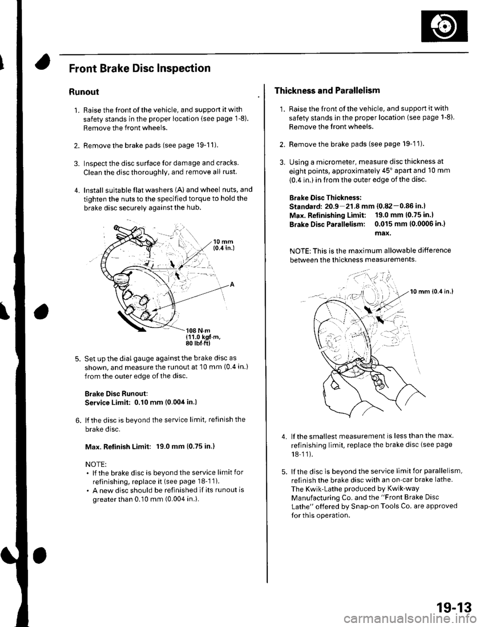
4. lnstall suita ble flat washers (A) andwheel nuts,and
tighten the nuts to the specified torque to hold the
brake disc securely against the hub.
Set up the dial gauge against the brake disc as
shown, and measure the runout at 10 mm (0 4 in.)
from the outer edge of the disc.
Brake Disc Runout:
Service Limit: 0.10 mm (0.00tt in.l
lf the disc is beyond the service limit, refinish the
brake disc.
Max. Retinish Limit: 19.0 mm (0.75 in.)
NOTE:. lf the brakedisc is beyondtheservice limitfor
refinishing, replace it (see page 18-1 1).
. A new disc should be refinished if its runout is
greater than 0.10 mm (0.004 in.).
Thickness and Parallelism
1. Raise the front of the vehicle, and support it with
safety stands in the proper location (see page 1-8).
Remove the front wheels.
2. Remove the brake pads (see page 19-11).
3. Using a micrometer, measure disc thickness at
eight points, approximately 45" apart and 10 mm
{0.4 in.) in from the outer edge of the disc.
Brake Oisc Thickness:
Standard: 20.9 21.8 mm {0.82-0.86 in.}
Max. Refinishing Limit: 19.0 mm 10.75 in.)
Brake Disc Parallelism: 0.015 mm 10.0(X)6 in.)
max.
NOTE: This is the maximum allowable difference
between the thickness measurements
10 mm lo.it in.l
lf the smallest measurement is less than the max.
refinishing limit, replace the brake disc (see page
18-11).
lf the disc is beyond the service limit for parallelism,
refinish the brake disc with an on-car brake lathe.
The Kwik-Lathe produced by Kwik-way
Manufacturing Co. and the "Front Brake Disc
Lathe" offered by Snap-on Tools Co. are approved
for this operation.
4.
': . --'t-'"'-
t,.
19-13
Page 609 of 1139
Conventional Brake Components
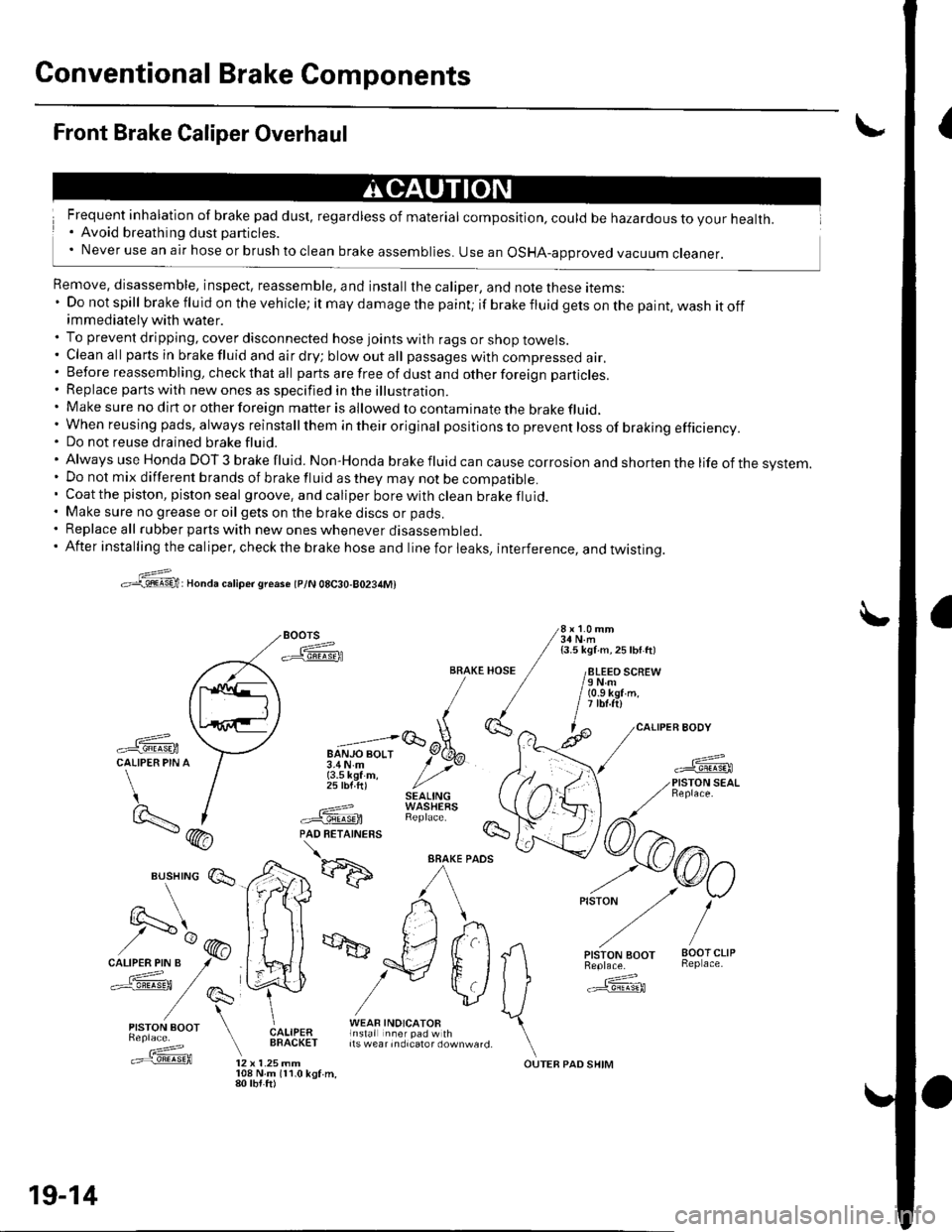
{Front Brake Caliper Overhaul
Frequent inhalation of brake pad dust, regardless of material composition, could be hazardous to your health.. Avoid breathing dust particles.' Never use an air hose or brush to clean brake assemblies. use an osHA-approved vacuum cleaner.
Remove, disassemble, inspect, reassemble, and install the caliper, and note these items:' Do not spill brake fluid on the vehicle; it may damage the paint; if brakefluidgetsonthepaint,washitoffimmediately with water.. To prevent dripping, cover disconnected hose joints with rags or shop towels.. Cleanall partsinbrakefluidandairdry;blowoutall passageswith compressed air.. Before reassembling, check that all parts are free of dust and other foreign particles.. Replace parts with new ones as specified in the illustration.. Make sure no dirt or other foreign matter is allowed to contaminate the brake fluid,' When reusing pads, always reinstallthem in their original pos itio ns to prevent loss of braking efficiency.. Do not reuse drained brake fluid.'AlwaysuseHondaDOT3brakefluid.Non'Hondabrakefluidcancausecorrosionandshortenthelifeofthesvstem.
. Do not mix different brands of brake fluid as they may not be compatible.. Coatthe piston, piston seal groove, and caliper borewithclean brakefluid.. Make sure no grease or oil gets on the brake discs or pads.. Replace all rubber parts with new ones whenever disassembled.. After installing the caliper, check the brake hose and line for leaks, interference, and twistinq.
>:@:Honda caliper sreaso tplN 08C30-80234M)
Boors 3i,l'1.'"
-ffiFA / isli\ii ^ zsw ttt
/paq\tl ll /
,\L,.'iE/ [
-ffi \--l u";;;lqEtCALIPER PIN A / 3.4N.m y' >vr / {3.5 kef m, / ,,' / 25 lbf ft) //'t / SEAL|NG)- I ---=-? WASHEaS
BRAKE HOSE / /8LEEO SCREW/ / /eNm/ / / (o.s kgr'm./ / | itbt.ftl,1(}', ^ l^ /caLl
-ffi \:7 "=;lGoX-
*fL-f
/) I .===? WAStrtXS \t9..- | #.'@ RepracF /7\- (hA PAD RETATNERS !s- / \
*d':ffi
^/rkr) ,-o/
vlJ ffi
Es,lry:' E*,e,a ["fif:i#l1t*"_,,. \.==f@ tz x t.zsmm ourEB paD sHrM
19-14
108 N.m 111.0 kgf.m,80 tbt.ft)
Page 610 of 1139
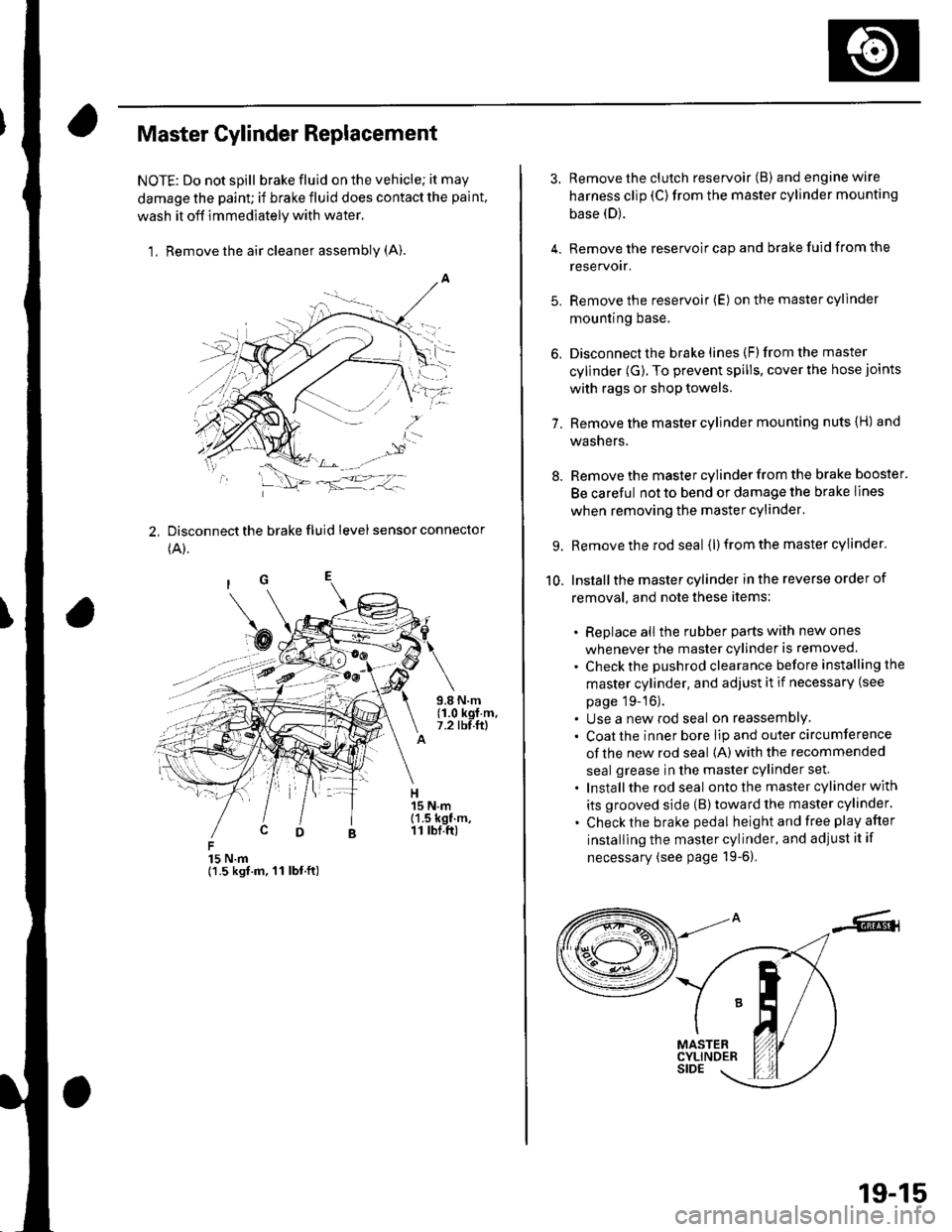
Master Cylinder Replacement
NOTE: Do not spill brake fluid on the vehicle; it may
damage the paint; if brake fluid does contact the paint,
wash it off immediately with water,
1, Remove the air cleaner assembly (A).
2, Disconnect the brake fluid level sensor connector
(A).
15 N.m{1.5 kgt.m, 11 lbt.ft)
3. Remove the clutch reservoir (B) andenginewire
harness clip (C)from the master cylinder mounting
base (D).
4. Remove the reservoir cap and brake fuid from the
reservoir.
5. Remove the reservoir (E) on the master cylinder
mountrng Dase.
6, Disconnect the brake lines (F)from the master
cylinder (G). To prevent spills, cover the hose joints
with rags or shop towels.
7. Remove the master cylinder mounting nuts {H) and
washers.
8. Remove the master cylinder from the brake booster.
Be careful not to bend or damage the brake lines
when removing the master cylinder.
9. Remove the rod seal (l) from the master cylinder.
10. Installthe master cylinder in the reverse order of
removal, and note these items:
. Replace all the rubber parts with new ones
whenever the master cylinder is removed.
. Check the pushrod clearance before installing the
master cylinder. and adjust it if necessary (see
page 19-16).. Use a new rod seal on reassemblY. Coat the inner bore lip and outer circumference
of the new rod seal {A) with the recommended
seal grease in the master cylinder set.
. Installthe rod seal ontothe master cylinder with
its grooved side (B)toward the master cylinder.
. Check the brake pedal height and free play after
installing the master cylinder, and adjust it if
necessary (see page 19-6).
19-15