Engine removal HONDA CIVIC 2003 7.G Workshop Manual
[x] Cancel search | Manufacturer: HONDA, Model Year: 2003, Model line: CIVIC, Model: HONDA CIVIC 2003 7.GPages: 1139, PDF Size: 28.19 MB
Page 36 of 1139
\.
Engine Electrical
Engine Electrical
SpecialTools
Starting System
Comoonent Location Index ...............
Circuit Diagram
Starter Circu it Troubleshooting
Clutch Interlock Switch Test
Starter Solenoid Test ..............
Sta rter Performance Test
Starter Reolacement ...............
Starter Overhaul .......................
lgnition System
Component Location Index ...............
Circuit Diagram
lgnition Timing Inspection
lgnition Coil Removal/1nsta11ation .......................
Spark Plug Inspection
Charging System
Component Location Index .................................. 4-2O
Circuit Diagram ........................... 4-21
Charging Circuit Troubleshooting ....................... 4-22
Drive Belt Inspection ................... 4-26
Drive Beft Replacement .............. 4-26
Drive BeftAuto-tensioner Inspection .................. 4-27
Drive Beft Auto-tensioner Replacement .............. 4-28
Alternator Reolacement ............. 4-29
Alternator Overhaul ................ .... 4-30
Cruise Control
Component Location Index .................................. 4-36
Circuit Diagram ........................... 4-37
Symptom Troubleshooting Index ....................... 4-38
Cruise Control Unit lnDut Test ............................. 4-40
Main Switch TesVReolacement ........................... 4-42
SeVResume/Cancel Switch TesVReplacement .. 4-42
Cruise Control Actuator Test ...... 4-43
Cruise Control Actuator/Cable Replacement ...... 4-44
Actuator Cable Adjustment .................................. 4-45
Clutch Pedal Position Switch Test ....................... 4-45
4-2
4-J
4-4
4-5
4-6
4-7
4-8
4-9
4-10
4-15
4-16
4-17
4-18
4- 19
-+
ENGINE
Page 44 of 1139
Starter Replacement
1. Make sure you have the anti-theft code for the radio.
then write down the frequencies for the radio's
preset buttons.
2. Disconnect the negative cable from the battery first,
then disconnect the positive cable.
3. Disconnect the knock sensor connector.
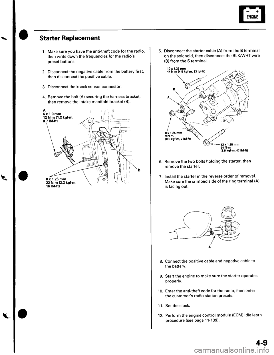
4. Remove the bolt (A) securing the harness bracket,
then remove the intake manifold bracket (B).
A6x1,0mm12 N.m {1.2 kgf.m,8.7 tbt.ft)
8 x 1.25 mm22 N,m 12.2 kgt.m,16 rbf.ftl
L't2.
4-9
5. Disconnect the starter cable (A)from the B terminal
on the solenoid, then disconnect the BLK,/WHT wire
{B) from the S terminal.
10 x 1.25 mm44 N.m {a.5 kgf.m,33lblft)
8 x 1.25 mm9Nm10.9 kgf.m,7 lbl ft)
7.
9.
'10.
11.
2
S'-12x12smm6ilNm{6.5 kgl m,47lbfft)
Remove the two bolts holding the starter, then
remove the starter.
lnstall the starter in the reverse order of removal.
Make sure the crimped side of the ring terminal (A)
is facing out.
Connect the positive cable and negative cable to
the batterY.
Start the engine to make sure the starter operates
propeny.
Enter the anti-theft code for the radio, then enter
the customer's radio station presets.
Set the clock.
Perform the engine control module (EcM) idle learn
procedure (see page 1 '1- 139 ).
I
Page 64 of 1139
l\-Alternator Replacement
1. Make sure you have the anti-theft code for the radio,
then write down the frequencies for the radio'spreset buttons,
2. Disconnect the negative cable from the battery first,
then disconnect the positive cable.
3. Remove the front bumper (see page 20-85).
4. Remove the right side headlight (see page 22-79).
5. Remove the reserve tank from the bracket.
6. Remove the drive belt (see page 4-26).
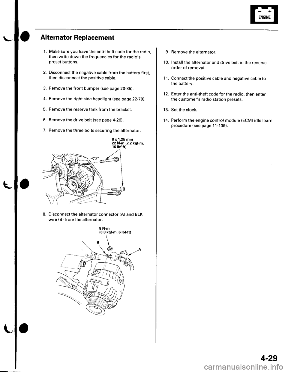
7. Remove the three bolts securing the alternator.
8 x 1.25 mm22 N.n 12.2 kgl.m,
Disconnect the alternator connector (A) and BLK
wire (B) from the alternator.
8 N.m10.8 kgf.m,6lbf.ft)
\
6
'I 1.
9.
10.
13.
14.
Remove the alternator.
Installthe alternator and drive belt in the reverse
order of removal.
Connect the positive cable and negative cable to
the battery.
Enter the anti-theft code for the radio, then enter
the customer's radio station presets.
Set the clock.
Perform the engine control module {ECM) idle learn
procedure (see page 11-139).
tt.
4-29
Page 82 of 1139
Engine Assembly
I
Engine Removal
Special Tools Required
Front subframe adapter EOS02C00001 1
NOTE:. Use fender covers to avoid damaging painted
surfaces.. To avoid damage, unplug the wiring connectors
carefully while holding the connector portion.. Mark all wiring and hoses to avoid misconnection.
Also, be sure that they do not contact other wiring orhoses, or interfere with other parts.
1. Secure the hood in the wide open position (support
rod in the lower hole).
2. Make sure you have the anti-theft code for the radio,
then write down the frequencies for the radio'spreset buttons.
3. Disconnect the negative cable from the battery first,then disconnect the positive cable.
4. Remove the battery.
5. Remove the intake manifold cover.
II
5-2
\,
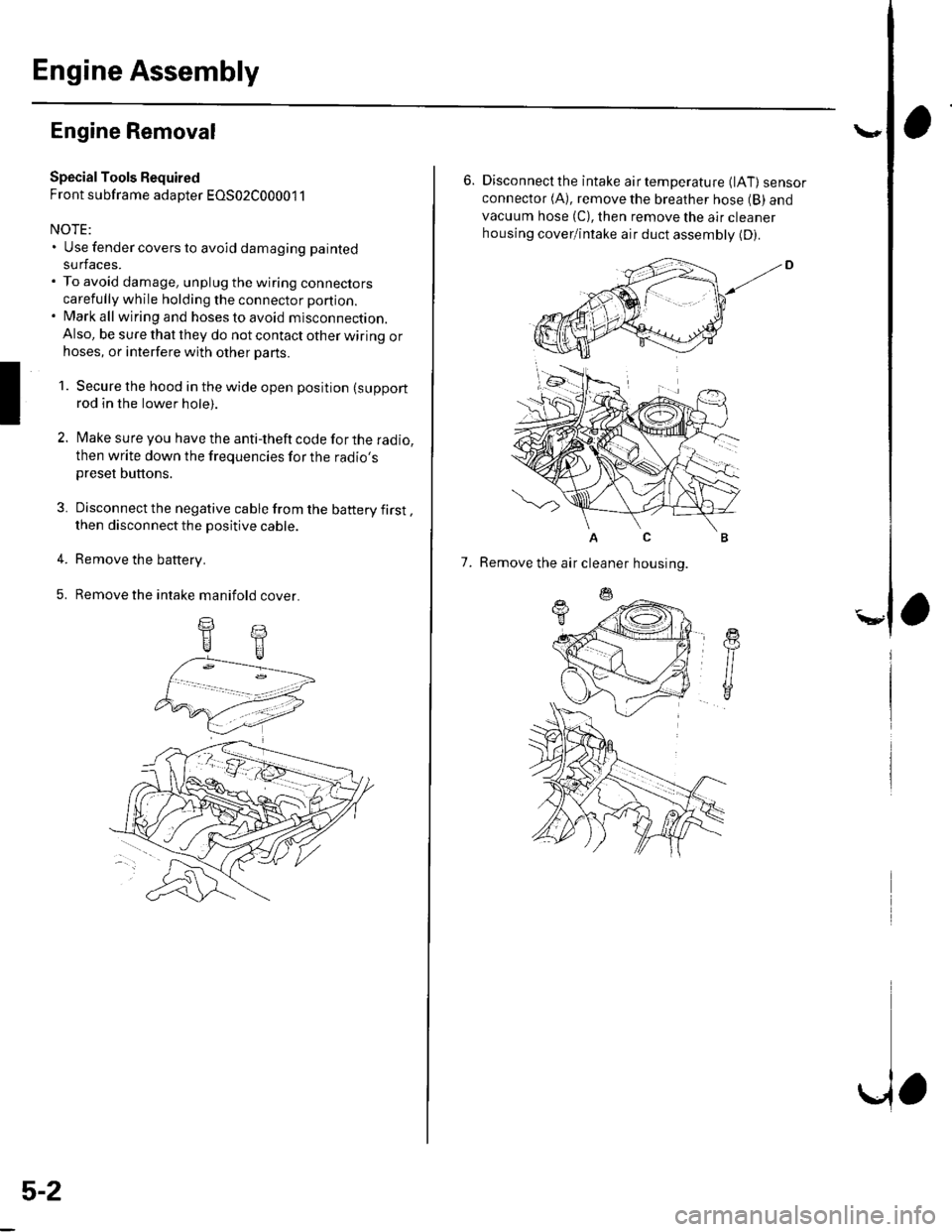
6. Disconnectthe intake airtemperature (lAT) sensorconnector (A), remove the breather hose (B) and
vacuum hose (C), then remove the air cleaner
housing cover/intake air duct assemblv (D).
AC
7. Remove the air cleaner housing.
Page 84 of 1139
Engine Assembly
Engine Removal (cont'dl
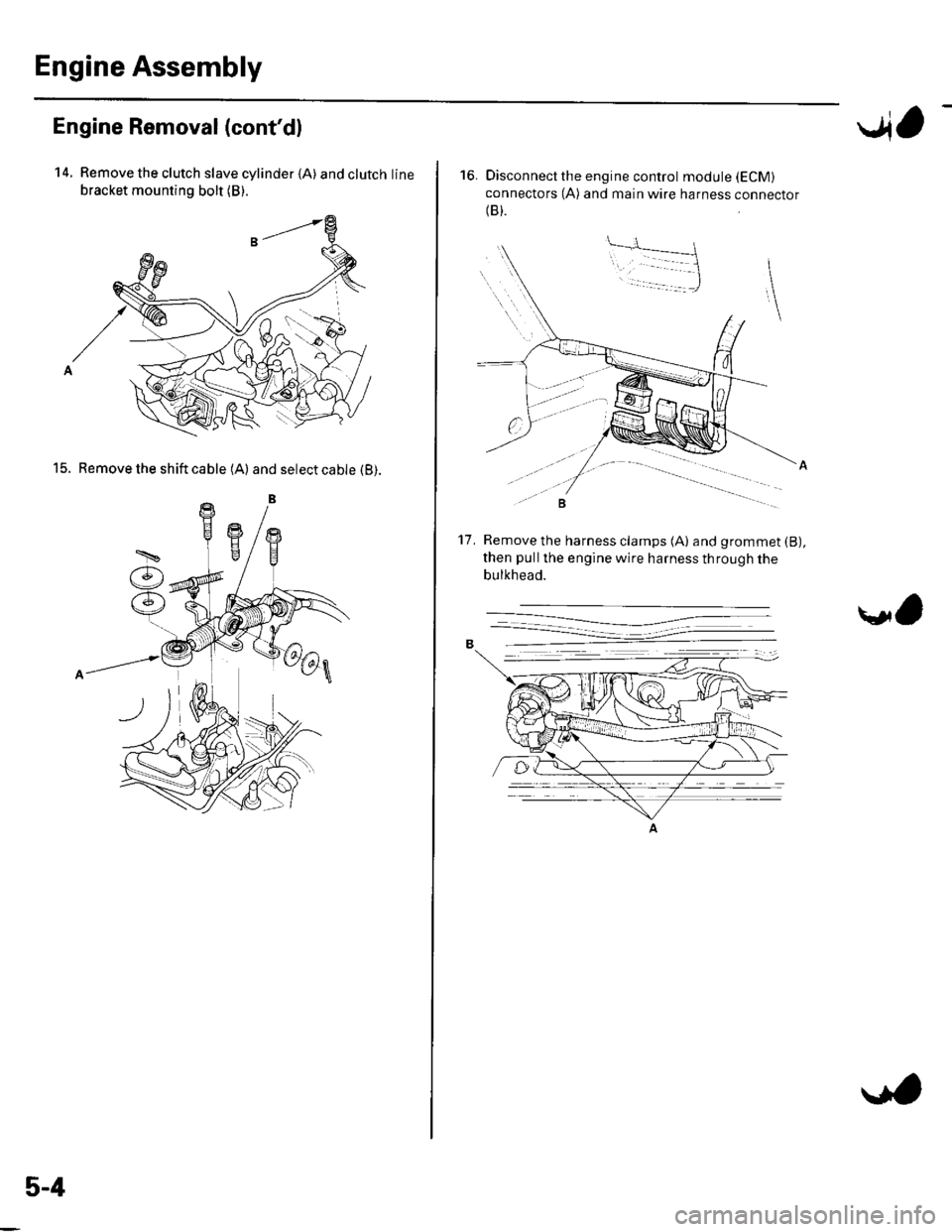
14. Remove the clutch slave cylinder {A) andclutchline
bracket mounting bolt (B).
15. Remove the shift cable (A) and select cable (B).
5-4
..4,
16. Disconnect the engine control module (ECM)
connectors (A) and main wire harness connector(B).
Remove the harness clamps (A) and grommet (B),
then pullthe engine wire harness through the
bulkhead.
't7 .
\l,
Page 86 of 1139
Engine Assembly
Engine Removal (cont'd)
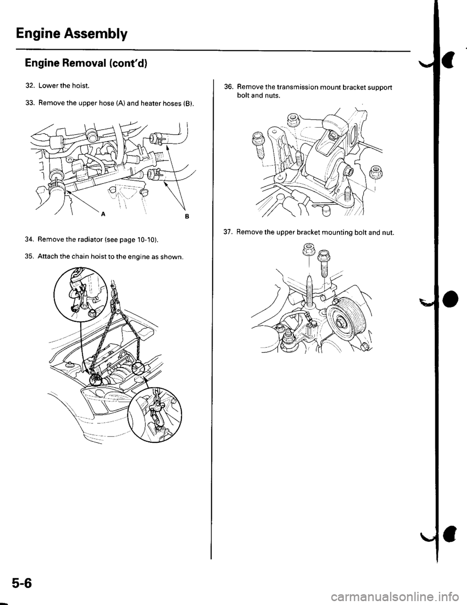
32. Lower the hoist.
33. Remove the upper hose (A)and heater hoses (B).
34. Bemove the radiator (see page 10-10).
35. Attach the chain hoist to the engine as shown.
5-6
36. Remove the transmission mount bracket support
bolt and nuts.
37. Remove the upper bracket mounting bolt and nut.
(.g
\a
Page 88 of 1139
Engine Assembly
Engine Removal (cont'd)
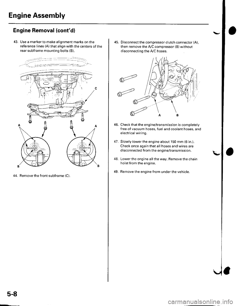
43. Use a marker to make alignment marks on the
reference lines (A) that align with the centers of the
rear subframe mounting bolts (B).
, !:_- _l.= :r -- ---.-','- -
44. Remove the front subframe (C).
5-8
ffi4
ffit'"
45. Disconnect the compressor clutch connector (A),
then remove the Ay'C compressor (B)without
disconnecting the A'./C hoses.
Check that the engine/transmission is completely
free of vacuum hoses, fuel and coolant hoses, and
electrical wiring.
Slowly lower the engine about 150 mm (6 in.).
Check once again that all hoses and wires are
disconnected trom the engine/transmission.
Lower the engine all the way. Remove the chain
hoist from the engine.
Remove the engine from under the vehicle.
46.
47.
48.
49.
Page 96 of 1139
\
Engine Mechanical
Cylinder Head
Special Tools
Comoonent Location Index
Engine Compression Inspection
VTEC Rocker Arm Test ........... ............ 6-7
VTC Actuator Inspection .................... 6-8
Valve Clearance Adjustment ............. 6-9
Crankshaft Pulley Removal and Installation .............. 6-11
Cam Chain Removal ........................... 6-12
Cam Chain Installation ....................... 6-15
Auto-Tensioner Removal/1nsta11ation ......................... 6-19
Chain Case Oil Seal Installation ........ 6-21
Cyf inder Head Cover Removal .......... 6-22
Cylinder Head Removal ..................... 6-23
WC Actuator. Exhaust Camshaft Sorocket
Repf acement .........6-24
Cylinder Head Inspection for Warpage ...................... 6-25
Rocker Arm Assembly Removal ................................. 6-26
Rocker Arms and Shafts
Disassembly/Reassembly .............. 6-27
Rocker Arms and Shafts Inspection ............................ 6-28
Camshaft Inspection .......................... 6-29
Valves, Springs, and Valve Seals Removal ................ 6-31
Valve Insoection ...................... ........... 6-32
Valve Stem-to-Guide Clearance Insoection ............... 6-32
Valve Guide Reolacement ................. 6-33
Valve Seat Reconditioning ................ 6-35
Valves, Springs, and Valve Seals Installation ............ 6-37
Rocker Arm Assemblv Installation .... 6-38
Cvlinder Head Installation ........................................... 6-39
Cylinder Head Cover Installation ...... 6-41
6-2
6-3
b-t'
Page 118 of 1139
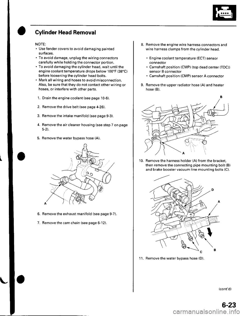
Gylinder Head Removal
NOTE:. Use fender covers to avoid damaging painted
surfaces.
To avoid damage, unplug the wiring connectors
carefully whlle holding the connector portion.
To avoid damaging the cylinder head, wait until the
engine coolant temperature drops below 100'F (38"C)
betore loosening the cylinder head bolts.
Mark all wiring and hoses to avoid misconnection.
Also, be sure that they do not contact other wiring or
hoses, or interfere with other parts.
'1.
2.
3.
Drain the engine coolant (see page 10-6).
Remove the drive belt (see page 4-26).
Remove the intake manifold {see page 9-3).
Remove the air cleaner housing (see step 7 on page
5-2t.
5. Remove the water bypass hose (A).
Remove the exhaust manifold (see page 9-7
Remove the cam chain (see page 6-12).
6.
7.
).
8. Remove the engine wire harness connectors and
wire harness clamps from the cylinder head.
. Engine coolant temperature (ECT) sensor
conneclor. Camshaft position (Cl\4P) (top dead center (TDC))
sensor B connector. Camshaft posilion (CMP) sensor A connector
9. Remove the upper radiator hose (A) and heater
hose (B).
'10. Remove the harness holder (A)from the bracket,
then remove the connecting pipe mounting boh {B)
and brake booster vacuum line mounting bolts {C).
(cont'd)
1 1. Remove the water bvpass hose (D).
6-23
Page 139 of 1139
Engine Mechanical
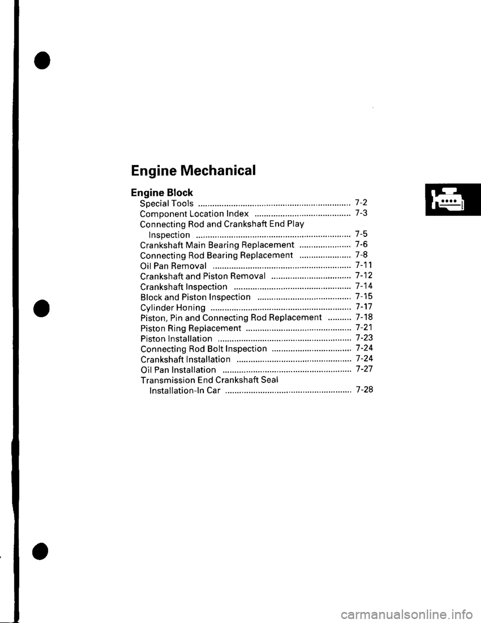
Engine Block
Soecial Tools ............. 7 -2
Comoonent Location Index ......................................... 7-3
Connecting Rod and Crankshaft End Play
InsDection .............. 7-5
Crankshaft Main Bearing Replacement ...................... 7-6
Connecting Rod Bearing Replacement ...................... 7-8
Oil Pan Removal ....................... .......... 7-11
Crankshaft and Piston Removal ........ 7-12
Crankshaft Inspection ........................ 7-14
Block and Piston Insoection ........................................ 7-15
Cyfinder Honing ............ .".................... 7 -'17
Piston, Pin and Connecting Rod Replacement .......... 7-18
Piston Ring Replacement ................... 7 -21
Piston lnstallation .................... ........... 7-23
Connecting Rod Bolt Inspection .......' 7 -24
Crankshaft lnstallation .....................'. 7-24
Oil Pan lnstallation .................. ........... 7 -27
Transmission End Crankshaft Seal
lnstallation-ln Car ................... ........' 7 -28