Socket HONDA CR-V 1997 RD1-RD3 / 1.G Workshop Manual
[x] Cancel search | Manufacturer: HONDA, Model Year: 1997, Model line: CR-V, Model: HONDA CR-V 1997 RD1-RD3 / 1.GPages: 1395, PDF Size: 35.62 MB
Page 88 of 1395
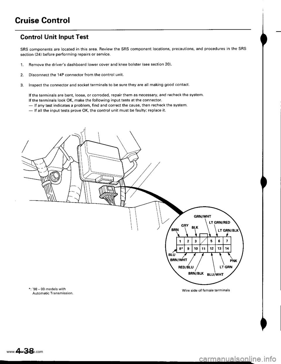
Cruise Control
Control Unit Input Test
SRS components are located in this area. Review the SRS component locations. precautions, and procedures in the SRS
section (241 before performing repairs or seryice.
'1. Remove the driver's dashboard lower cover and knee bolster {see section 20).
2. Disconnect the 'l4P connector from the control unit.
3. Inspect the connector and socket terminals to be sure they are all making good contact
lf the terminals are bent, loose, or corroded, repair them as necessary, and recheck the system.
lf the terminals look OK, make the following input tests at the connector.- lf any test indicates a problem. find and correct the cause, then recheck the system.
- lf all the input tests prove OK, the control unit must be faulty; replace it.
*: '98 - 00 models withAutomatic Transmission.Wire side ol female terminals
4-38
www.emanualpro.com
Page 115 of 1395
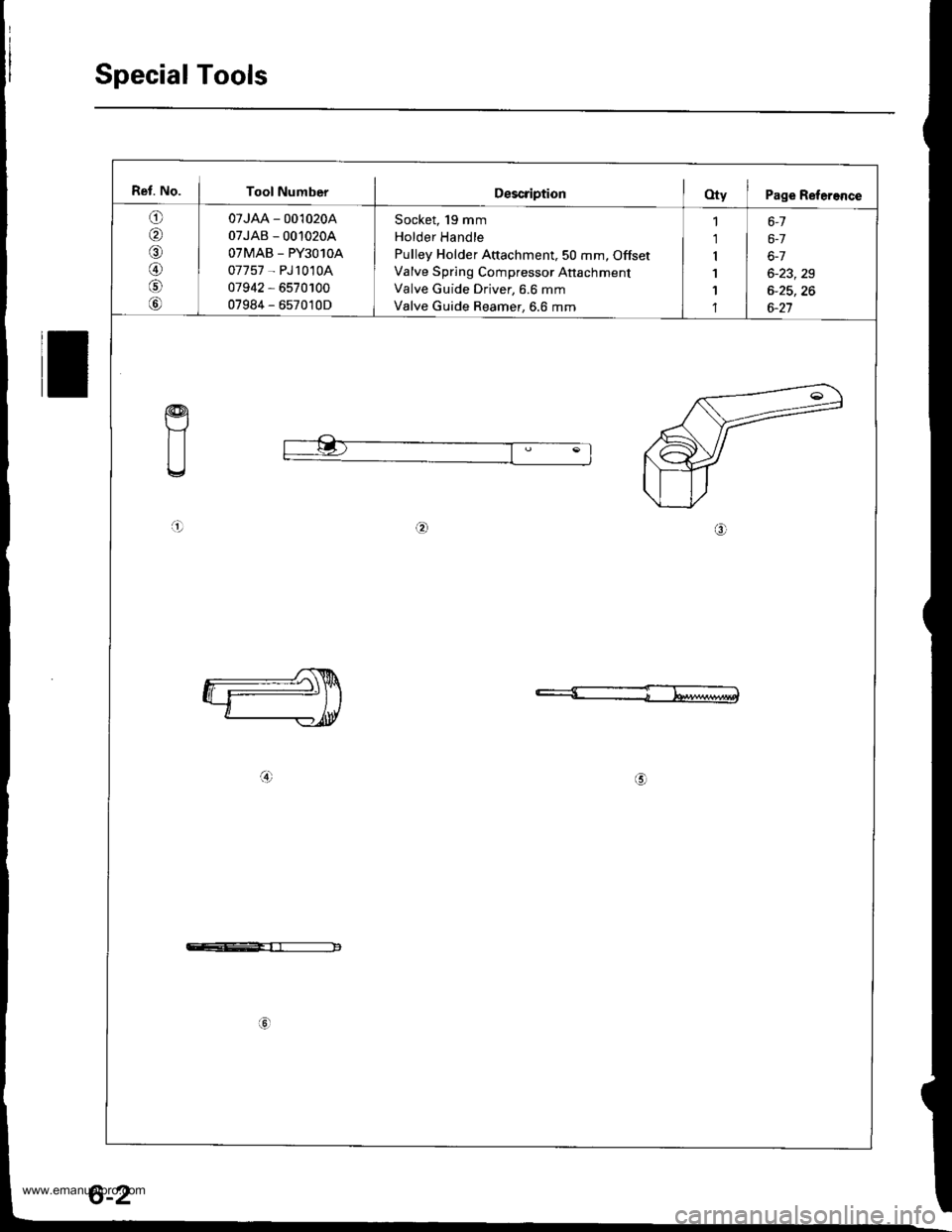
Special Tools
Ref. No. I Tool NumberDescription(Xy I Page Refereflce
o
,61
A)
07JAA - 001020A
07JAB - 00'10204
OTMAB _ PY3O1OA
07757 - PJ1010A
07942 - 6570100
07984 - 657010D
Socket, 19 mm
Holder Handle
Pulley Holder Attachment,50 mm, Offset
Valve Spring Compressor Anachment
Valve Guide Driver, 6.6 mm
Valve Guide Reamer, 6.6 mm
1 6-1
1 | 6-7
r I 6-7
1 6-23,29
1 I 6-25,26'l | 6-27
a!)
a!)
c--E-rr------------
6-2
www.emanualpro.com
Page 120 of 1395
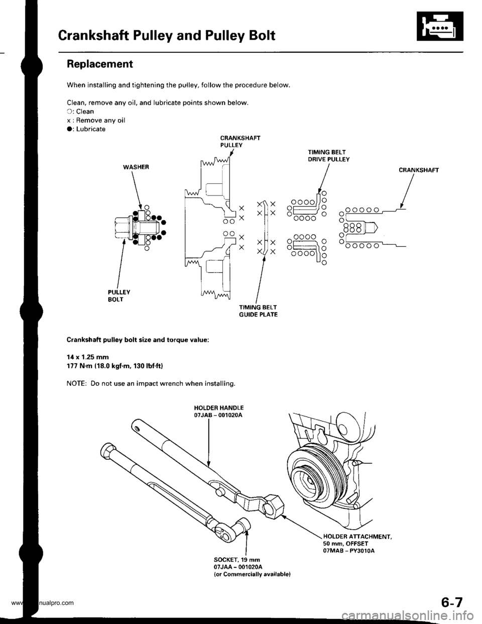
Crankshaft Pulley and Pulley Bolt
Replacement
When installing and tightening the pulley, follow the procedure below.
Clean, remove any oil, and lubricate points shown below.
C: Clean
x I Remove any oil
a: Lubricate
CRANKSHAFTPULLEY
XXX
Xo
X
X
X
X
CRANKSHAFT
oooo
- oooo
oooo
oooo
Crankshaft pulley bolt size and torque value:
14 x 1.25 mm
177 N'm (18.0 kgf.m, 130 lbt.ftl
NOTE: Do not use an impact wrench when installing.
HOLDER ATTACHMENT.50 mm, OFFSETOTMAB - PY3OlOA
SOCKET, 19 mm07JAA - 001020A
{or Commercially available}
WASHER
^ oooo
6r.
Ro".
6-7
www.emanualpro.com
Page 136 of 1395
Valves, Valve Springs
and Valve Seals
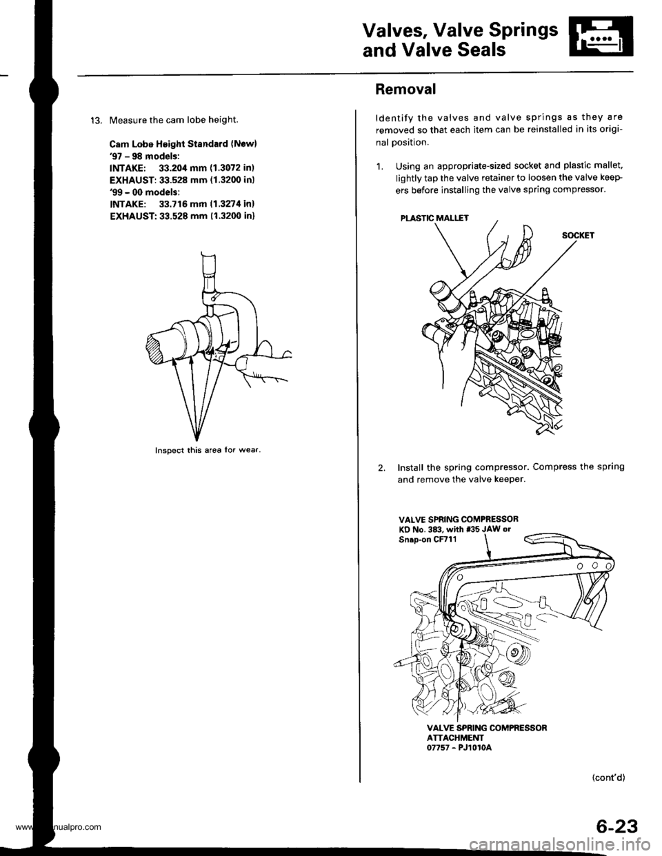
13. Measure the cam lobe height.
Cam Lobe Height Standard (Newl'97 - 98 models:
INTAKE: 33.20,1mm (1.3072 in)
EXHAUST: 33.528 mm (1.3200 inl'99 - 00 models:
INTAKE: 33.716 mm 11.327t1in)
EXHAUST:33.528 mm (1.3200 in)
Inspect this area lor wear.
Removal
ldentify the valves and valve springs as they are
removed so that each item can be reinstalled in its origi-
nal Dosition.
1. Using an appropriate-sized socket and plastic mallet.
lightly tap the valve retainer to loosen the valve keeP
ers before installing the valve spring compressor'
2. Install the spring compressor. Compress the spring
and remove the valve keeper.
VALVE SPRING COMPRESSORKD No. 3&!. whh *'5 JAW o.
VALVE SPRING COMPRESSORATTACHMEUT07757 - PJ1010A
(cont'd)
6-23
www.emanualpro.com
Page 463 of 1395
Mainshaft Assembly
Clearance Inspection
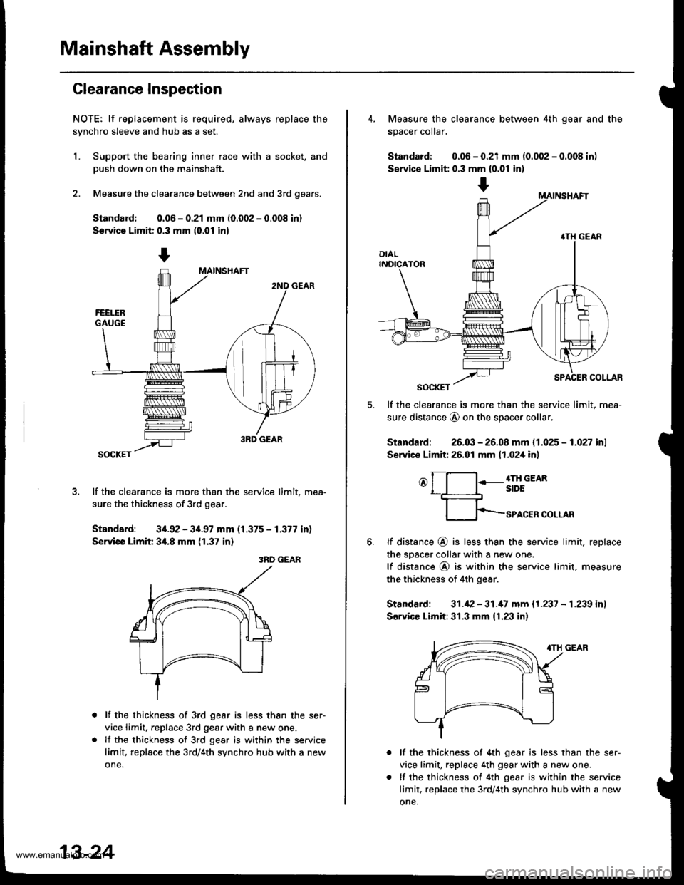
NOTE; lf replacement is required, always replace the
synchro sleeve and hub as a set.
L Support the bearing inner race with a socket. and
Dush down on the mainshaft.
2. Measure the clearance between 2nd and 3rd oears.
Siandard: 0.06 - 0.21 mm 10.002 - 0.008 in)
Servica Limit: 0.3 mm (0.01 in)
lf the clearance is more than the service limit, mea-
sure the thickness of 3rd gear.
Standard: 34.92 - 34.97 mm {1.375 - 1.377 in)
Service Limit 34.8 mm (1.37 in)
3RD GEAR
lf the thickness of 3rd gear is less than the ser-
vice limit, replace 3rd gear with a new one.
lf the thickness of 3rd gear is within the service
limit, replace the 3rd/4th synchro hub with a new
one.
13-24
+
4. Measure the clearance between 4th gear and the
spacer coIar,
Standard: 0.06 - 0.21 mm {0.002 - 0.008 in)
Servic€ Limit: 0.3 mm {0.01 inl
lf the clearance is more than the service limit, mea-
sure distance @ on the spacer collar,
Standard: 26.03 - 26.08 mm {1.025 - 1.027 inl
Service Limit: 26.01 mm {1.02,[ in]
o[-l:-g;;em
fp-rro.ERcoLLAR
6.tf distance @ is less than the service limit, replace
the sDacer collar with a new one.
lf distance @ is within the service limit. measure
the thickness of 4th gear.
Standard: 31.42 - 31.'17 mm 11.237 - L239 inl
Sarvicc Limit:31.3 mm {1.23 in)
lf the thickness of 4th gear is less than the ser-
vice limit, replace 4th gear with a new one.
lf the thickness of 4th gear is within the service
limit, replace the 3rd/4th synchro hub with a new
one,
www.emanualpro.com
Page 464 of 1395
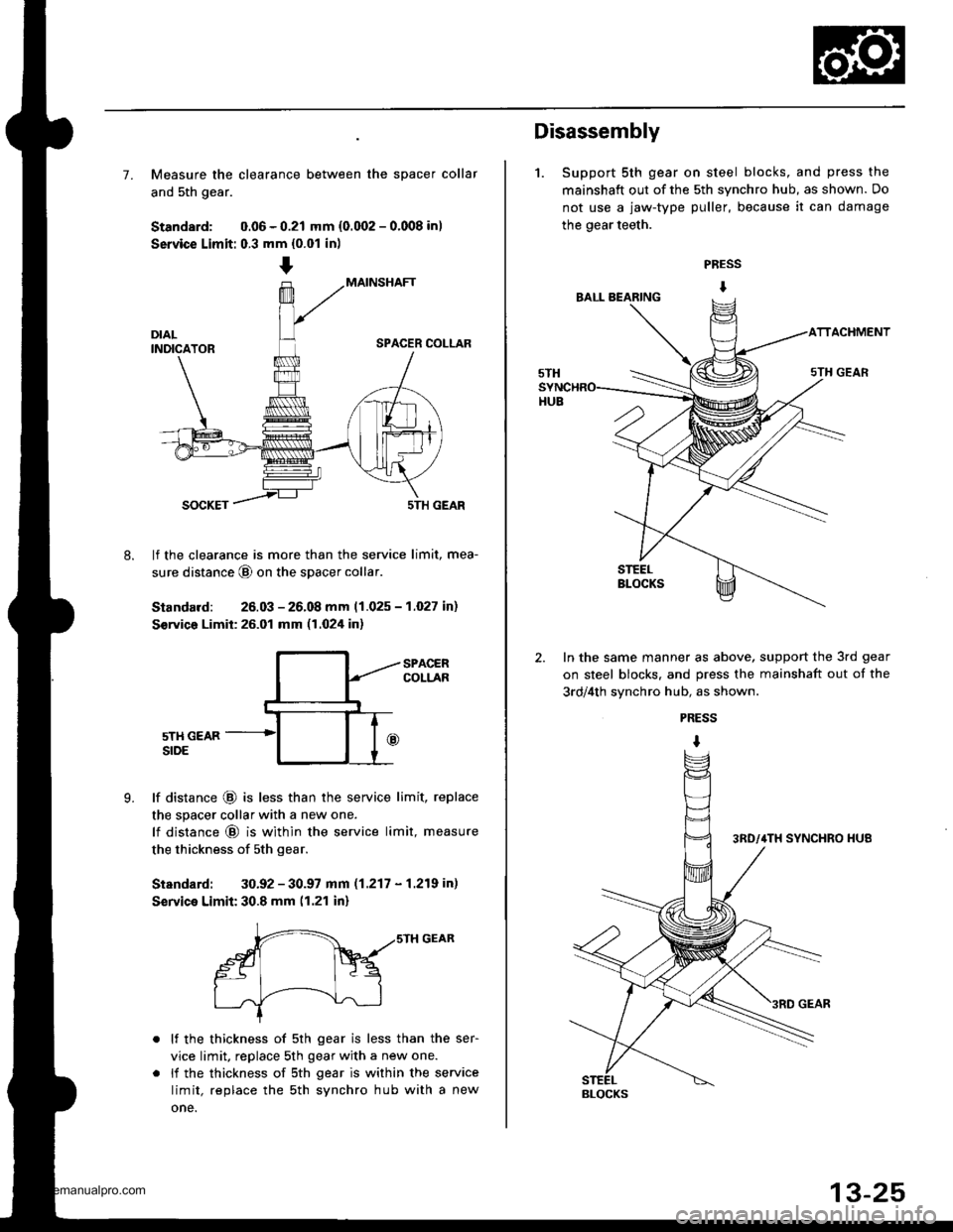
7. Measure the clearance between the spacer collar
and 5th gear.
Standard: 0.06 - 0.21 mm {0.002 - 0.008 in)
Service Limit: 0.3 mm {0.01 in)
MAINSHAFT
SPACER COLLAR
8.
SOCKET5TH GEAR
lf the clearance is more than the service limit, mea-
sure distance @ on the spacer collar
Standard: 26.03 - 26.08 mm 11.025 - 1.027 in)
S€rvico Limit: 26.01 mm (1.024 in)
9.
SPACERCOLLAR
5TH GEARSIDE
lf distance @ is less than the service limit, replace
the spacer collar with a new one.
lf distance @ is within the service limit, measure
the thickness of sth gear.
Standard: 30.92 - 30.97 mm (1.217 - 1.219 in)
Service Limit: 30.8 mm (1.21 in)
r-- ,,srH GEAR
gt Fq
I .J'-----!--\--J-l
lf the thickness of 5th gear is less than the ser-
vice limit, replace 5th gear with a new one.
li the thickness of sth gear is within the service
limit, replace the sth synchro hub with a new
one.
Disassembly
1. Support 5th gear on steel blocks, and press the
mainshaft out of the 5th synchro hub, as shown. Do
not use a jaw-type puller, because it can damage
the gear teeth.
PRESS
I
ACHMENT
In the same manner as above, support the 3rd gear
on steel blocks. and press the mainshaft out of the
3rd/4th svnchro hub, as shown.
PRESS
I
BLOCKS
www.emanualpro.com
Page 470 of 1395
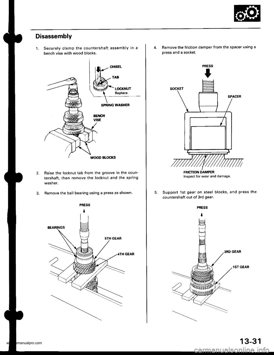
Disassembly
1.
2.
Securely clamp the countershaft assembly in a
bench vise with wood blocks.
SPRIiIG WASHEF
BETICHvtsE
W(X)D BLOCKS
Raise the locknut tab from the groove in the coun-
tershaft, then remove the locknut and the spring
washer.
Remove the ball bearing using a press as shown.
CHISEL
4. Remove the Jriction damper from the spacer using a
press and a socket.
Support lst gear on steel blocks, and press the
countershaft out of 3rd gear.
PRESS
t
5.
PRESS
I
3RD GEAR
1ST GEAR
FRICTION DAMPERInspect lor wear and damage.
13-31
www.emanualpro.com
Page 658 of 1395

A/T Gear Position Indicator
1.
f nput Test -'97 - 98 Models
Remove the gauge assembly from the dashboard (see section 20). and disconnect the 14P connector from the gauge
assemblv (see section 23),
Inspect the connector and socket terminals to be sure they are all making good contact.
. lf the terminals are bent, loose, or corroded, repairthem as necessary, and recheck the system.. lf the terminals look OK, make the following input tests at the 14P connector.- lf I test indicates a problem, find and correct the cause, then recheck the system.- lf all the input tests prove OK, but the indicator is faulty. replace the printed circuit board,
GAUGE ASSEMBLY 14P CONNECTOR
Wire side of female terminals
CavityWirs
ColorTest ConditionTest: Desir€d ResultPossible Cause
{lf rosult is not obtainod)
YEL
lgnition switch ON (ll)Check for voltage to ground:
There should be battery voltage,
. Blown No. 25 (7.5 A) fuse in the
under-dash fuse/relay box. An open in the wire
RE D/BLKCombination light
switch ON and dash
lights brightness con-
trol dial on full bright
Check for voltage between No. 2
and No. 3 terminals;
There should be battery voltage.
Blown No. 47 (7.5 A) fuse in the
under-dash fuse/relay box
Faulty combination Iight switch
Faulty dash iight brightness
controller
An open in the wire
RED
4BLUShift lever in ECheck for continuity to ground:
There should be continuity.
NOTE: There should be no continu-
ity in any other shift lever position.
' Faulty Ay'T gear position switch. An open in the wireBRNShift lever in E
7YELShift lever in @
8BLKUnder all conditionsCheck for continuity to ground:
There should be continuity
. Poor ground {G401). An open in the wire
9GRN/BLK
lgnition switch ON {ll)
and shift lever in any
position except E
Check for voltage to ground:
There should be battery voltage
for two seconds after the ignition
switch is turned ON {ll), and less
than 1 V two seconds later,
' Faulty PCM. An open in the wire
10GRNShift lever in ECheck for continuity to ground:
There should be continuity.
NOTE: There should be no conti-
nuity in any other shift lever posi-
UOn.
. Faulty A,ff gear position switch. An open in the wire1'lREDShift lever in @
12WHTShift lever in E
BLVBLU
Shift lever in ENOTE: Do not push
the brake pedal.
14LT GRN
lgnition switch ON { ll)
and shift lever in any
position except E and
E
Check for voltage to ground:
There should be about 5 V.
. Faulty PCM. An open in the wire
14-142
www.emanualpro.com
Page 659 of 1395

L
Input Test -'99 - 00 Models
Remove the gauge assembly from the dashboard {see section 20), and disconnect the 14P connector from the gauge
assembly (see section 23).
Inspect the connector and socket terminals to be sure they are all making good contact.
a lf the terminals are bent. loose, or corroded. repair them as necessary. and recheck the system.
. lf the terminals look OK, make the following input tests at the 14P connector.- lf a test indicates a problem, find and correct the cause, then recheck the system.- lf all the input tests prove OK, but the indicator is faulty, replace the printed circuit board.
GAUGE ASSEMBLY 14P CONNECTOR
Wire side of female terminals
CavityWire
ColorTest ConditionTest: Desired ResuhPossible Caus6
{lf resutt is not obtainod)
1YEL
lgnition switch ON (ll)Check for voltage to ground:
There should be battery voltage.
. Blown No.25 (7.5 A) fuse in the
under-dash fuse/relay box. An open in the wire
2RE D/BLK
Combination light
switch ON and dash
lights brightness con-
trol dial on full bright
Check for voltage between No. 2
and No.3 terminals:
There should be battery voltage.
Blown No. 47 {7.5 A) fuse in the
under-dash fuse/relay box
Faulty combination light switch
Faulty dash light brightness
controller
An open in the wire
5RED
BRNShift lever in ECheck for continuity to ground:
There should be continuity.
NOTE: There should be no continu-
ity in any other shift lever position.
. Faulty A/T gear position switch. An open in the wire7YELShift lever in E
'10BLUShift lever in E
LT BLU
lgnition switch ON (ll),
shift lever in E. and
Over-Drive is OFF bypressing O/D switch.
Check for continuity to ground:
There should be continuity.
Faulty O/D switch
Faulty A/T gear position switch
Faulty PCM
An open in the wire
8BLKUnder all conditionsCheck for continuity to ground:
There should be continuity
. Poor ground (G401)
. An open in the wire
9a:FI\|/Et| ta
lgnition switch ON (ll)
and shift lever in any
position except E
Check for voltage to groundl
There should be battery voltage
for two seconds after the ignition
switch is turned ON (ll). and less
than 1 V two seconds later.
. Faulty PCM. An open in the wire
11REDShift lever in SCheck for continuity to ground:
There should be continuity.
NOTE: There should be no conti-
nuity in any other shift lever posi-
Iton.
. Faulty A/T gear position switch. An open in the wire12WHTShift lever in E
BLI(BLU
Shift lever in ENOTE: Do not push
the brake pedal.
14LT GRN
lgnition switch ON (ll)
and shift lever in any
position except E and
E
Check for voltage to groundl
There should be about 5 V,
. Faulty PCM. An open in the wire
14-143
www.emanualpro.com
Page 873 of 1395
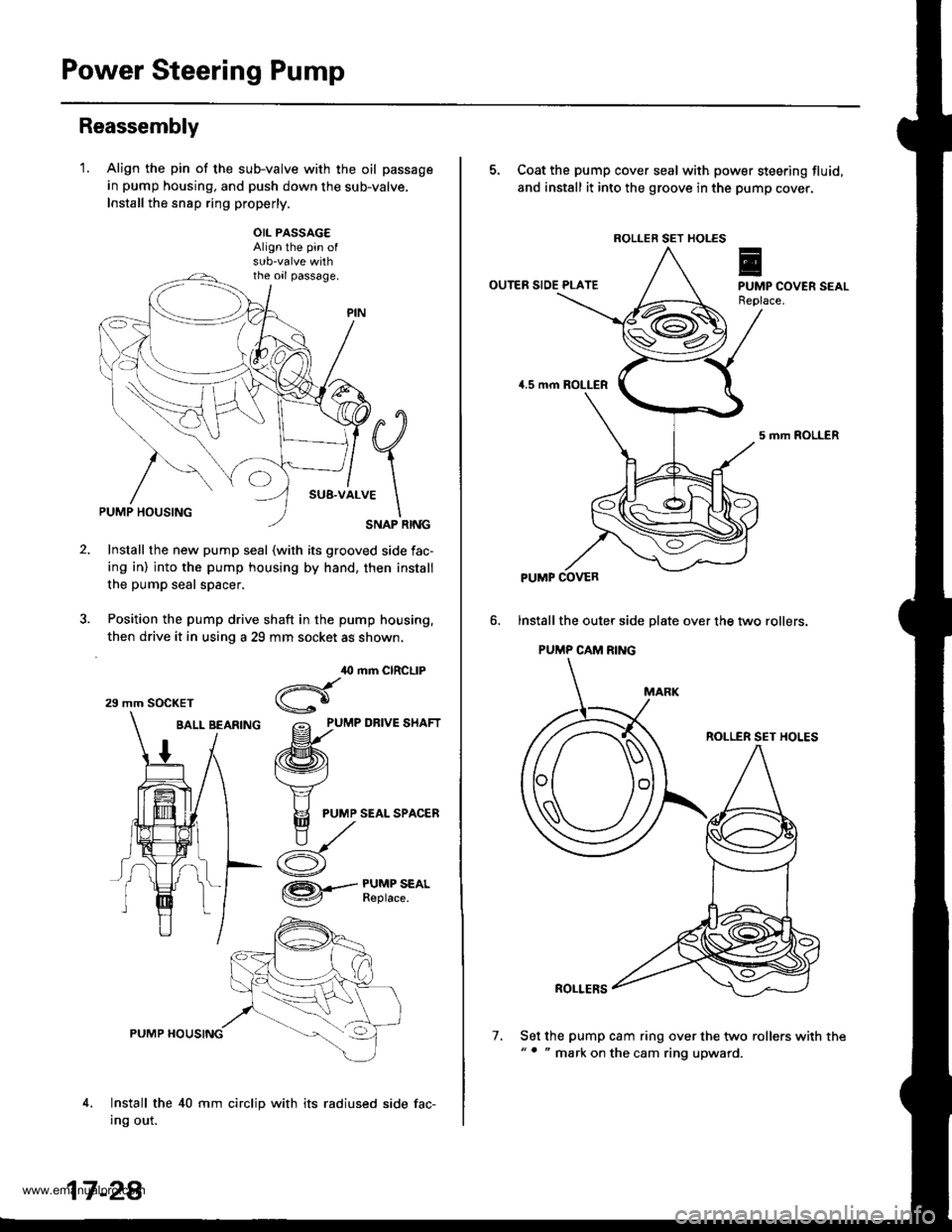
Power Steering Pump
Reassembly
'1.Align the pin of the sub-valve with the oil passage
in pump housing, and push down the sub-valve.
Install the snsp ring properly.
OIL PASSAG€Align the pin of
the oil passage.
#q
;1..*
\SNAP RINGPUMP HOUSING
Install the new pump seal (with its grooved side fac-
ing in) into the pump housing by hand, then install
the pump seal spacer.
Position the pump drive shaft in the pump housing,
then drive it in using a 29 mm socket as shown,
BALL BEARfNG grlu,e un.t
/ /ffi\
1 / t\v4
t/ Y
# I F
PUMP SEALSPAC,ER
ry^
i- d
,O mm CIRCLIP
Hgo
/= PUMP DRIVE SHAFT
@.--#$i":*'
4,
PUMP HOUSING
Install the 40 mm circlip with its radiused side fac-
Ing out.
29 mm SOCKET
17 -2A
7.
5. Coat the pump cover seal with power steering fluid,
and install it into the groove in the pump cover.
OUTER SIDE PLATE
5 mrh ROLLER
lnstall the oute. side plate over the two rollers.
PUMP CAM RING
ROLLER SET HOLES
ROLLERS
Set the pump cam ring over the two rollers with the"' " mark on the cam ring upward.
ROLLER SET HOLES
PUMP COVER
www.emanualpro.com