Pump HONDA CR-V 1998 RD1-RD3 / 1.G Owners Manual
[x] Cancel search | Manufacturer: HONDA, Model Year: 1998, Model line: CR-V, Model: HONDA CR-V 1998 RD1-RD3 / 1.GPages: 1395, PDF Size: 35.62 MB
Page 678 of 1395
Pressure Testing
(cont'd)
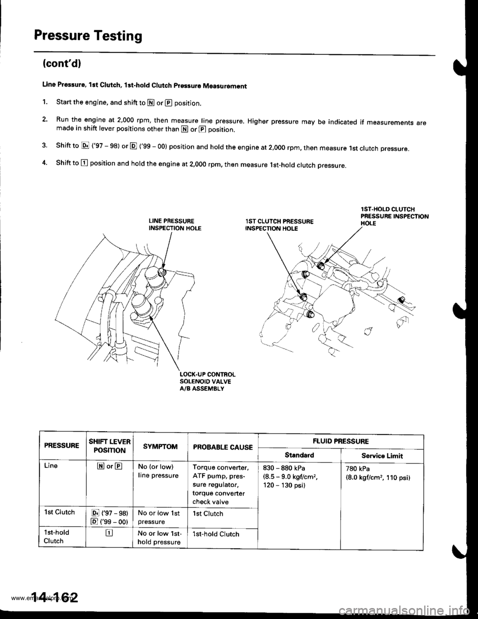
Line Proslure, lst Clutch, lst.hold Clutch prsssuro Measuromont
1. Start the engine, and shift to E or @ position.
2. Run the engine at 2,000 rpm, then measure line pressure. Higher pressure may be indicated if measurements aremade in shift lever positions other than E or @ position.
shift to E ('97 - 98) or E ('99 - oo) position and hold the engine at 2.ooo rpm, then measure 1st clutch pressure.
Shift to E position and hold the engine at 2,000 rpm, then measure lst-hotd ctutch Dressure.
LOCK.UP CONTROLSOLENOID VALVEA/B ASSEMBLY
4.
PRESSURESHIFT LEVER
POSmONSYMPTOMPROBABLE CAUSEFLUID PRESSURE
StandaldService Limit
LineEor@No (or low)
line pressure
Torque converter.
ATF pump, pres-
sure regulator,
torque converter
check valve
830 - 880 kPa(8.5 * 9.0 kgflcm,,
120 - '130 psi)
780 kPa
{8.0 kgf/cm,, 'l10 psi)
1st ClutchE (97 - 98)
E ('se - oo)
No or low 1st
pressurelst Clurch
lst-hold
ClutchtrNo or low lst-
hold pressure1st-hold Clutch
14-162
www.emanualpro.com
Page 695 of 1395
oa;\,6
G)!o,
a@,6
@o(a
@(}
@a@@@@@@@6@@)@@@@@@@@@@@@@
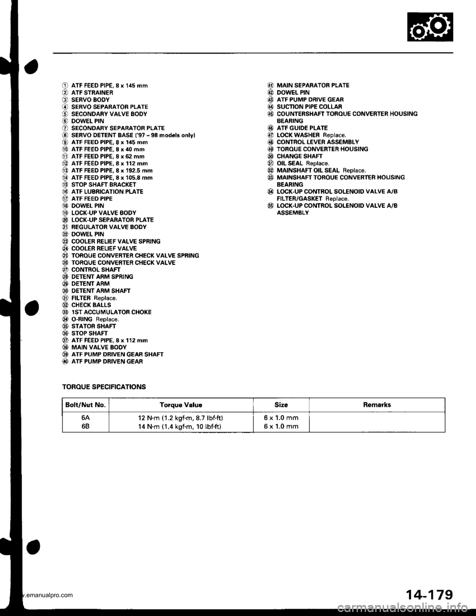
ATF FEED PIPE,8 x 145 mmATF STRAINERSERVO BODYSERVO SEPARATOR PLATESECONDARY VALVE EODYDOWEL PINSECONDARY SEPARATOR PLATESERVO DETENT BASE ('97 - 98 model3 onlylATF FEED PIP€, 8 x 145 mmATF FEED PIPE,8 x 40 mmATF FEED PIPE. 8 x 62 mmATF FEED PIPE.8 x 112 mmATF FEED PIPE, 8 x 192.5 mmATF FEEO PIPE. I x 105.8 mmSTOP SHAFT BRACKETATF LUBRICATION PLATEATF FEEO PIPEDOWEL PINLOCK-UP VALVE EODYLOCK-UP SEPARATOR PLATEREGULATOR VALVE BODYDOWEL PINCOOLER RELIEF VALVE SPRINGCOOLER RELIEF VALVETOROUE CONVERTER CHECK VALVE SPRINGTOROUE CONVERTER CHECK VALVECONTROL SHAFTOETENT ARM SPRINGOETENT ARMDETENT ARM SHAFTFILTER Replace.CHECK BALLSlST ACCUMULATOR CHOKEO"RING Replace.STATOR SHAFTSTOP SHAFTATF FEED PIPE, I x 112 mmMAIN VALVE BOOYATF PUMP DRIVEN GEAR SHAFTATF PUMP DRIVEN GEAR
TOROUE SPECIFICATIONS
MAIN SEPARATOR PLATEDOWEL PINATF PUMP DRIVE GEARSUCTION PIPE COLLARCOUNTERSHAFT TOROUE CONVERTER HOUSINGBEARINGATF GUIDE PLATELOCK WASHER Replace.CONTROL LEVER ASSEMBLYTOROUE CONVERTER HOUSINGCHANGE SHAFTOIL SEAL Reolace.MAINSHAFT OIL SEAL Reolace.MAINSHAFT TOROUE CONVERT€R HOUSINGBEARINGLOCK.UP CONTROL SOLENOID VALVE A/BFILTER/GASKET Replace.LOCK.UP CONTROL SOLENOID VALVE A/BASSEMBLY
@@@@@
@@@@@@@@
@
@
Bolt/Nut No.Torque ValugSizeRomarks
64
6B
12 N'm (1.2 kgf.m,8.7 lbf.ft)
14 N.m (1.4 kgf.m, 10 lbf.ft)
6x1.0mm
6x1.0mm
14-179
www.emanualpro.com
Page 701 of 1395
![HONDA CR-V 1998 RD1-RD3 / 1.G Owners Manual
ai_la2,
(41/4.:4.
\7)
1.0)tl
(3]
t9.1q
oo,ID@,8!Itt\,29
€4
69
aa.21
600toa
04
6!)ent00t.@
ATF FEED PIPE, I x 145 mm
ATF STRAINERSERVO BODYSERVO SEPARATOB PLATESECONDABY VALVE BOOYDOWEL PINSECONDAR HONDA CR-V 1998 RD1-RD3 / 1.G Owners Manual
ai_la2,
(41/4.:4.
\7)
1.0)tl
(3]
t9.1q
oo,ID@,8!Itt\,29
€4
69
aa.21
600toa
04
6!)ent00t.@
ATF FEED PIPE, I x 145 mm
ATF STRAINERSERVO BODYSERVO SEPARATOB PLATESECONDABY VALVE BOOYDOWEL PINSECONDAR](/img/13/5778/w960_5778-700.png)
ai_la2',
(41/4.:4.
\7)
1.0)tl
(3]
t9.1q
oo,ID@,8!Itt\,29
€4
69
aa.21
600toa
04
6!)ent00t.@
ATF FEED PIPE, I x 145 mm
ATF STRAINERSERVO BODYSERVO SEPARATOB PLATESECONDABY VALVE BOOYDOWEL PINSECONDARY SEPARATOR PLATE
SERVO DETENT BASE ('98 model onlvl
ATF FEED PIPE, 8 x 145 mmATF FEED PIPE.8 x 40 mmATF FEED PIPE,8 x 62 mmATF FEED PIPE, I x 112 mm
ATF FEED PIPE, 8 x 192.5 mm
ATF FEED PIPE, 8 x 105.8 mm
STOP SHAFT BRACKETATF LUERICATION PLATEATF FEED PIPEDOWEL PINLOCK-UP VALVE BODYLOCK-UP SEPARATOR PLATE
REGULATOR VALVE BOOYDOWEL PINCOOLER RELIEF VALVE SPRINGCOOLER BELIEF VALVETOROUE CONVERTER CHECK VALVE SPRING
TOROUE CONVERTER CHECK VALVECONTNOL SHAFTDETENT ARM SPRINGDETENT ARMDETENT ARM SHAFTFILTER Replace.CHECK BALLS1ST ACCUMULATOR CHOKEO-RING Replace.STATOR SHAFTSTOP SHAFTATF FEED PIPE. 8 x 112 mmMAIN VALVE BODYATF PUMP DRIVEN GEAR SHAFTATF PUMP DRIVEN GEAR
MAIN SEPARATOR PLATE
DOWEL PINATF PUMP DRIVE GEARSUCTION PIPE COLLARCOUNTEBSHAFT TOROUE CONVERTER HOUSING
BEARINGATF GUIDE PLATEATF MAGNETTOBOUE CONVERTER HOUSINGOIL SEAL Beplace.MAINSHAFT OIL SEAL Replace.MAINSHAFT TOROUE CONVERTER HOUSING
BEARINGLOCK.UP CONTROL SOLENOID VALVE A/B
FILTER/GASKET Replace.LOCK-UP CONTROL SOLENOID VALVE A/B
ASSEMELY
i4ll(4d
@@.!!l
art)@@@@li]t
TOROUE SPECIFICATIONS
Bolt/Nut No.Torque ValueSizeRemarks
12 N.m (1.2 kgim,8.7 lbf'tt)6x1.0mm
14-185
www.emanualpro.com
Page 706 of 1395
Torque Converter Housing/Valve Body
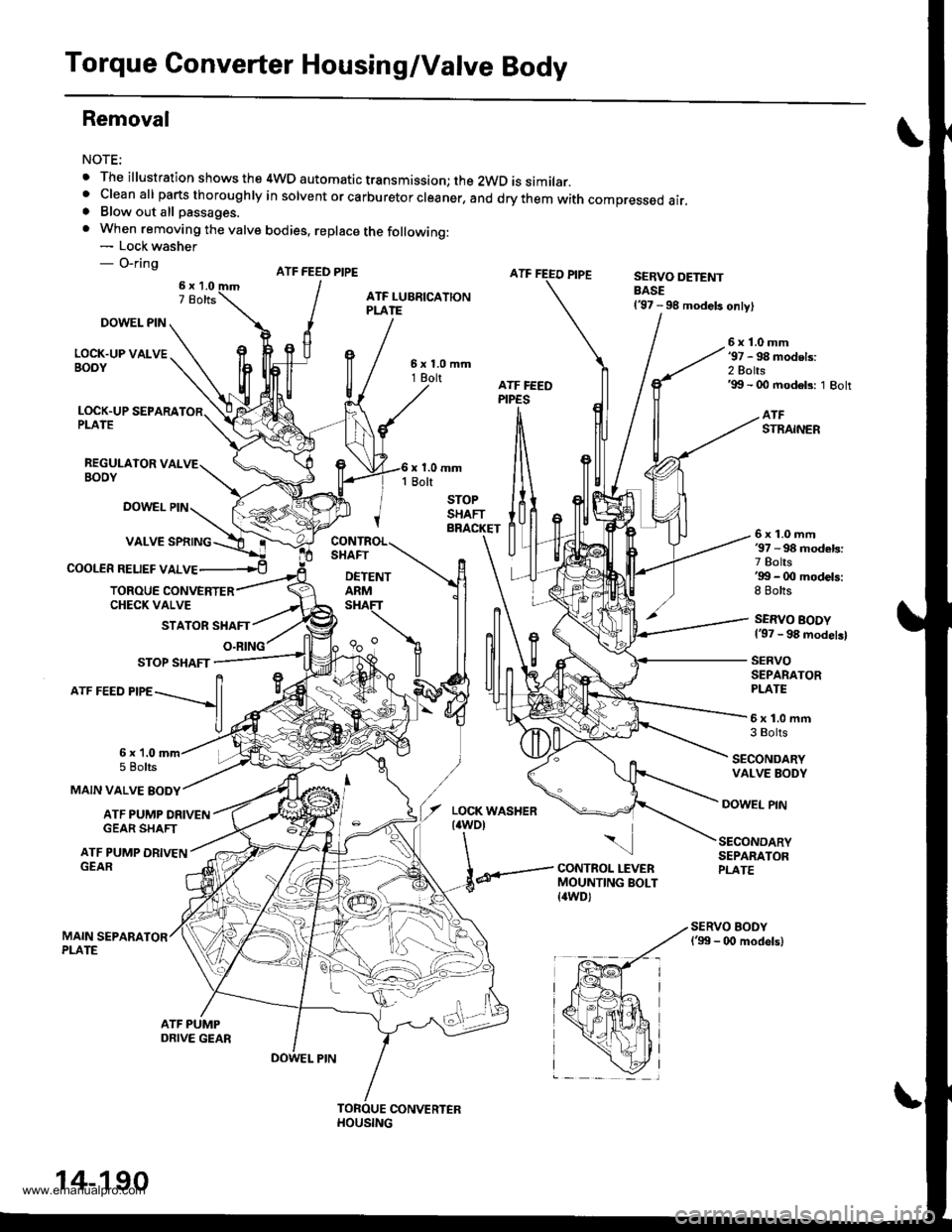
Removal
NOTE:
. The illustration shows the 4WD automatic transmission; the 2WD is similar.' cleanall parts thoroughry in sorvent or carburetor creaner, and drythem with compressed air.. Blow out all passages.
. When removing the valve bodies, replace the following:- Lock washer- O-ringATF FEED PIPESERVO DETENTBASE137 - 98 models only)
DOWEL PIN
LOCK.UP VALVEBOOY
6x1.0mm'97 - 98 models:2 Bolts'99 - 00 modeb: 1 Bolt
LOCK.UP SEPARAPLATE
REGULAIOR VALVEBOOY
ATFSTRAINER
DOWEL PIN
COOLER RELIEF VALVE
6x1.0mm37 - 98 models:7 Bolts'gg - 0O models:8 Bolts
SERVO BODY137 - 98 modelsl
SERVOSEPARATORPLATE
TOROUE CONVERTERCHECK VALVE
STATOR SHAFT
O.RING
5x1.0mfi3 Bolts
SECONDARYVALVE BODY
MAIN VALVE BODY
6x 1.05 Bolts
ATF PUMP ORIVENGEAR SHAFT
DOWEL PIN
ATF PUMP DRIVENGEAR
\
CONTROL LEVERMOUNTING BOLT{awD)
SECONDARYSEPARATORPLATE
14-190
www.emanualpro.com
Page 707 of 1395
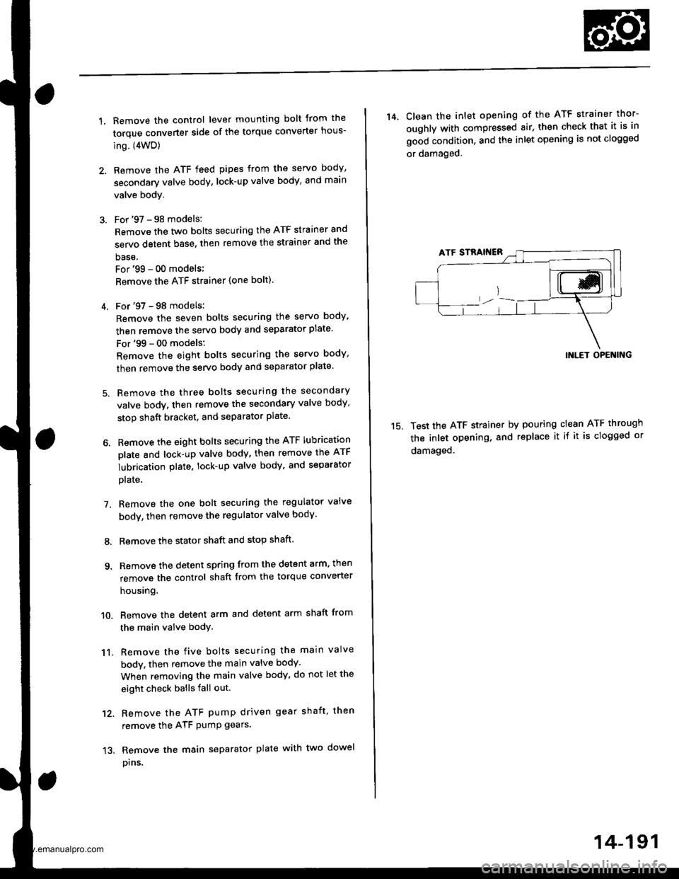
1.Remove the control lever mounting bolt trom the
torque converter side of the torque converter hous-
ing. (4WD)
Remove the ATF feed pipes from the servo body,
secondary valve body, lock-up valve body, and main
valve body.
For '97 - 98 models:
Remove the two bolts securing the ATF strainer and
servo detent base, then remove the strainer and the
base.
For'99 - 00 models;
Remove the ATF strainer {one bolt).
4. For'97 - 98 models:
Remove the seven bolts securing the servo body,
then remove the servo body and separator plate'
For'99 - 00 models:
Remove the eight bolts securing the servo body,
then remove the servo body and separator plate'
5. Bemove the three bolts securing the secondary
valve body, then remove the secondary valve body'
stop shaft bracket, and separator plate.
6. Remove the eight bolts securing the ATF lubrication
plate and lock-up valve body, then remove the ATF
lubrication plate, lock-up valve body' and separator
plate.
7. Remove the one bolt securing the regulator valve
body, then remove the regulator valve body'
8. Remove the stator shaft and stop shaft.
9. Remove the detent spring from the detent arm, then
remove the control shaft from the torque converter
houslng.
10. Remove the detent arm and detent arm shaft from
the main valve body.
11. Remove the five bolts securing the main valve
body, then remove the main valve body.
When removing the main valve body, do not let the
eight check balls fall out.
12. Remove the ATF pump driven gear shaft, then
remove the ATF PumP gears.
13. Remove the main separator plate with two dowel
prns.
14, Clean the inlet opening of the ATF strainer thor-
oughly with compressed air, then check that it is in
good condition, and the inlet opening is not clogged
or damaged.
15.
INLET OPENING
Test the ATF strainer by pouring clean ATF through
the inlet opening, and replace it if it is clogged or
damaged.
14-191
www.emanualpro.com
Page 711 of 1395
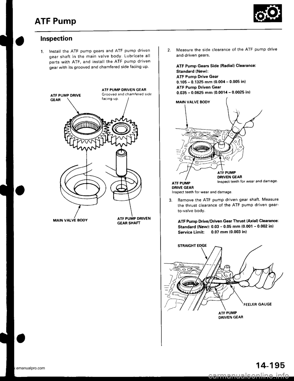
ATF Pump
Inspection
1. Install the ATF pump gears and ATF pump driven
gear shaft in the main valve body Lubricate all
parts with ATF, and install the ATF pump driven
gear with its grooved and chamfered side facing up
MAIN VALVE AOOY
ATF PUMP ORIVE
2. Measure the side clearance of the ATF pump drive
and driven gears.
ATF Pump Gears Side {Radial} Cloarance:
Standard (Newl:
ATF Pump Drive Gear
0.105 - 0.1325 mm {0.004 - 0.005 in}
ATF Pumo Driven Gear
0.035 - 0.0625 mm {0.0014 - 0.0025 in)
MAIN VAI-VE BOOY
fl
L/
ATF PUMPDRIVE GEAR
ATF PUMPDRIVEN GEARInspecl teeth {or wear and damage
Inspect teeth for wear and damage,
3. Remove the ATF pump driven gear shaft Measure
the thrust clearance of the ATF pump driven gear-
to-valve body.
ATF Pumo Drive/Driven Gear Thrust (Axiall Clearance:
Standard (N€w): 0.03 - 0.05 mm {0'001 - 0 002 inl
Service Limit: 0.07 mm 10.003 in)
ATF PUMPORIVEN GEAR
14-195
www.emanualpro.com
Page 766 of 1395
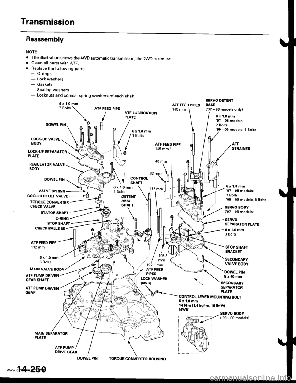
Transmission
Reassembly
NOTE:
. The illustration shows the 4WD automatic transmission; the 2WD is similar.. Clean all parts with ATF.. Replace the following parts:- O-rings- Lock washers- Gaskets- Sealing washers- Locknuts and conical spring washers of each shaft
ATF FEED PIPE
/
ATF FEED PIPES145 mm
SERVO DETENTBASE(37 -98 modeb onlylATF LUBRICATIONPLATE6x1.0mm
2 Bolts'99 - 00 models: 1 Bolts
LOCK.UP VALVEBODY
LOCK.UP SEPARATORPLATE
REGULATOR VALVEBODY
DOWEL PIN
DOWEL PIN
VALVE SPRING
STATOR SHAFT
'-
'112mmll,
rlT
ATFSTRAINER
40 mm
j coNrRoLI SHAFT
COOLER BELIEF VALVE
TOROUE CONVERTERCHECK VALVE
6x1.0mm18olts
DETENTARMSHAFT
6x1,0mm'97 - 98 models:7 Bolts'99 - 00 models:8 Bolts
SERVO BODY('97 - 98 models)
SERVOSEPARATOR PLATE
6x1.0mm3 Bolts
STOP SHAFTBRACKET
SECONDARYVALVE BODY
OOWEL PIN8x40mm
O.RING
STOP SHAFTCHECK BALLS 18'
ATF FEED PIPE112 mm
6x1.0mm5 Eolts
ATF PUMP DRIVENGEAR SHAFT
ATF PUMP DRIVEN
MAIN SEPARATORPLATE
MAIN VALVE EOOY
SECONDARYSEPARATOR
d---.- PLATE--.- CONTROL I.EVER MOUNTING BOLT6x1.0ftm14 N.m (1.4 kgt.m, 10 tbf.ft)(4WD)SERVO BODY('99 - 00 models)
ATF PUMP
6x1.0mm
ATF FEEO PIPE
) / 105.8
/,,!.,::(./ afF FEEO,/ ptpEs
EP,---!ir{+*a r
fpffi4 i
x*hi
_ \zl
14-250
DRIVE GEAR
DOWEL PINTOBOUEHOUSING
www.emanualpro.com
Page 767 of 1395
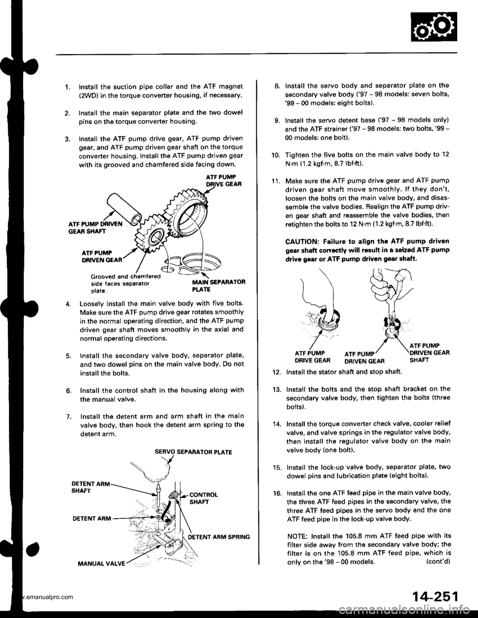
1.Install the suction pipe collar and the ATF magnet
{2WD) in the torque converter housing, if necessary.
lnstall the main seDarator Dlate and the two dowel
pins on the torque converter housing,
Install the ATF pump drive gear. ATF pump driven
gear, and ATF pump driven gear shaft on the torque
converter housing. Installthe ATF pump driven gear
with its grooved and chamfered side facing down.
ATF PUMPGEAR
ATF PUMP D{IVEf{GEAR SHAFT
ATF PUi'PORIVEN GEAR
Grooved and chamteredside faces separatorplate.
MAIN S€PAR/ATORPLATE
5.
o.
Loosely install the main valve body with five bolts.
Make sure the ATF pump drive gear rotates smoothly
in the normal operating direction, and the ATF pump
driven gear shaft moves smoothly in the axial and
normal operating directions.
Install the secondary valve body, separator plate,
and two dowel pins on the main valve body. Do not
installthe bolts.
Install the control shaft in the housing along with
the manual valve.
lnstall the detent arm and arm shaft in the main
valve body, then hook the detent arm spring to the
detent arm.
SEBVO SEPARATOR PLATE
7.
DETENT ARMSHAFT
OETENT ARM
CONTROLSHAFT
MANUAL VAIVE
OETENT ARM SPRING
onlv on the '98 - 00 models,
14-251
1l.
9.
8.
10.
Install the servo body and separator plate on the
secondary valve body ('97 - 98 models: seven bolts,'99 - 00 models: eight bolts).
lnstall the servo detent base ('97 - 98 models only)
and the ATF strainer ('97 - 98 models: two bolts,'99 -
00 models: one boltl.
Tighten the five bolts on the main valve body to 12
N'm (1.2 kgf.m, 8.7 lbf.ft).
Make sure the ATF pump drive gear and ATF pump
driven gear shaft move smoothly. lf they don't,
loosen the bolts on the main valve body, and disas-
semble the valve bodies. Realign the ATF pump driv-
en gear shaft and reassemble the valve bodies, then
retighten the bolts to 12 N.m (1.2 kgim, 8.7 lbf.ft).
CAUTION: Failure to align the ATF pump driven
gear shaft corroctly will rosult in a seizsd ATF pump
drive gear or ATF pump drivon gear shaft.
ATF PUMP ATFGEARDRIVE GEAR DBIVEN GEARSHAFT
Install the stator shaft and stop shaft
Install the bolts and the stop shaft bracket on the
secondary valve body, then tighten the bolts (three
bolts).
Install the torque converter check valve, cooler relief
valve, and valve springs in the regulator valve body,
then install the regulator valve body on the main
valve body {one boltl.
Install the lock-up valve body, separator plate, two
dowel pins and lubrication plate (eight bolts).
Installthe one ATF feed pipe in the main valve body,
the three ATF feed pipes in the secondary valve, the
three ATF feed pipes in the servo body and the one
ATF feed pipe in the lock-up valve body.
NOTE: lnstall the 105.8 mm ATF feed pipe with its
filter side away from the secondary valve body; the
filter is on the 105.8 mm ATF feed pipe, which is(cont'd)
13.
14.
15.
16.
www.emanualpro.com
Page 791 of 1395
Differential
Rear Differential
Special Tools .......... ...........15-2
Description
Rear Differential ................................. 15-4
Hydraulic Flow ............ ,.. 15-6
Real-time 4WD-Dual Pump System
Troub|eshootin9 ................................. 15-10
Rear Differential Assembly
Troubleshooting ................................. 15-13
Maintenance
Differential Fluid ........... . 15-14
Rear Differential Assembly
lllustrated Index .......... .. 15-15
Removal/lnstallation .... 15-16
Differential Carrier Assembly
Leak Repair .................... 15-18
OilSeals
Replacement ...,................................... 15-19
Rear Differential Assembly
Disassembly ..........,......., 15-20
Reassembly .................... 15-23
www.emanualpro.com
Page 794 of 1395

Description
Rear Differential
Outline
The Real-time 4WD-Dual Pump System model has a hydraulic clutch and a differential mechanism in the rear differential
assembly. Under normal conditions, the vehicle is driven by the front wheels. However, depending on to the driving force
of the front wheels and the road conditions. the system instantly transmits appropriate driving force to the rear wheels
without requiring the driver to switch between 2WD (tront wheel drive) and 4WD (four wheel drive). The switching mecha-
nism between 2WD and 4WD is integrated into the rear differential assembly to make the system light and compact.
ln addition, the dual-pump system switches off the rear-wheel-drive force when braking in a forward gear. This allows the
braking system to work properly on models equipped with an Anti-lock Braking System (ABS).
Construction
The rear differential assembly consists of the torque control differential case assembly and the rear differential carrier
assembly. The torque control differential case assembly consists of the differential clutch assembly, the companion
flange, and the oil pump body assembly. The rear differential carrier assembly consists of the differential mechanism. The
differential drive and driven gears are hypoid gears.
The oil pump body assembly consists of the front oil pump, the rear oil pump, the hydraulic control mechanism, and the
clutch piston. The clutch piston has a disc spring that constantly provides the differential clutch assembly with a preset
torque to Drevent abnormal sound.
The clutch guide in the differential clutch assembly is connected to the propeller shaft via the companion flange, and it
receives the driving force lrom the transfer assembly. The clutch guide rotates the clutch plate and the front oil pump in
the oil pump body.
The clutch hub in the differential clutch assembly has a clutch disc that is splined with the hypoid drive pinion gear. The
hypoid drive gear drives the rear oil pump.
The front and rear oil pumps are trochoidal pumps. The rear oil pump capacity is 2.5 percent larger that the front oil pump
to handle the rotation difference between the front and rear wheels caused by worn front tires and tight corner braking.
The oil pumps are designed so the fluid intake works as a fluid discharge when the oil pumps rotate in reverse. Genuine
Honda CVT fluid is used instead of differential fluid.
Operation
When there is a difference in rotation speed between the front wheels (clutch guide) and rear wheels (hypoid driven gear),
hydraulic pressure from the front and rear oil pumps engages the differential clutch, and drive force from the transler
assembly is applied to the rear wheels.
The hydraulic pressure control mechanism in the oil pump body selects 4WD mode when the vehicle is started abruptly,
or when accelerating in a forward or reverse gear (causing rotation difference between the front and rear wheels). or
when braking in reverse gear {when decelerating). lt switches to 2WD mode when the vehicle is driven at a constant speed
in forwar! or reverse gear (when there is no rotation difference between the front and rear wheels), or when braking in a
fo rwa rd gear (when decelerating).
To protect the system, the differential clutch assembly is lubricated by hydraulic pressure generated by the oil pumps in
both 4WD and 2WD modes. Also, the thermal switch relieves the hydraulic pressure on the clutch piston and cancels 4WD
mode if the temDerature of the differential fluid rises above normal.
www.emanualpro.com