Pump HONDA CR-V 1998 RD1-RD3 / 1.G Workshop Manual
[x] Cancel search | Manufacturer: HONDA, Model Year: 1998, Model line: CR-V, Model: HONDA CR-V 1998 RD1-RD3 / 1.GPages: 1395, PDF Size: 35.62 MB
Page 795 of 1395
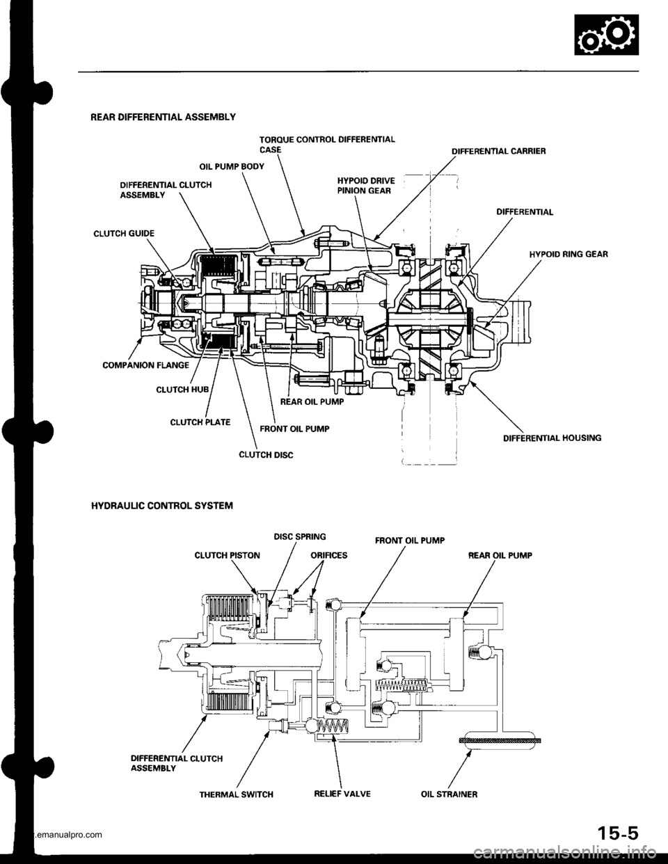
TOROUE CONTROL OIFFERENTIAL
REAR DIFFERENTIAL ASSEMBLY
OIL PUMP BODY
OIFFERENTIAL CLUTCHHYPOID DRIVEPINION GEAR
OIFFERENTIAL CARRIER
DIFFERENTIAL
HYPOID RING GEAR
DIFFERENTIAI- HOUSING
REAR OII- PUMP
ASSEMBLY
CLUTCH GUIDE
COMPANION FLANG€
CLUTCH HUB
CLUTCH PLATE
HYDRAULIC CONTROL SYSTEM
CLUTCH PISTON
CLUTCH DISC
REAR OIL PUMP
FRONT OIL PUMP
DISC SPRINGFRONT OIL PUMP
DIFFEREMT|AL CLUTCHASSEMBI-Y
THERMAL SWITCHRELIEF VALVEOIL STRAINER
15-5
www.emanualpro.com
Page 796 of 1395
Description
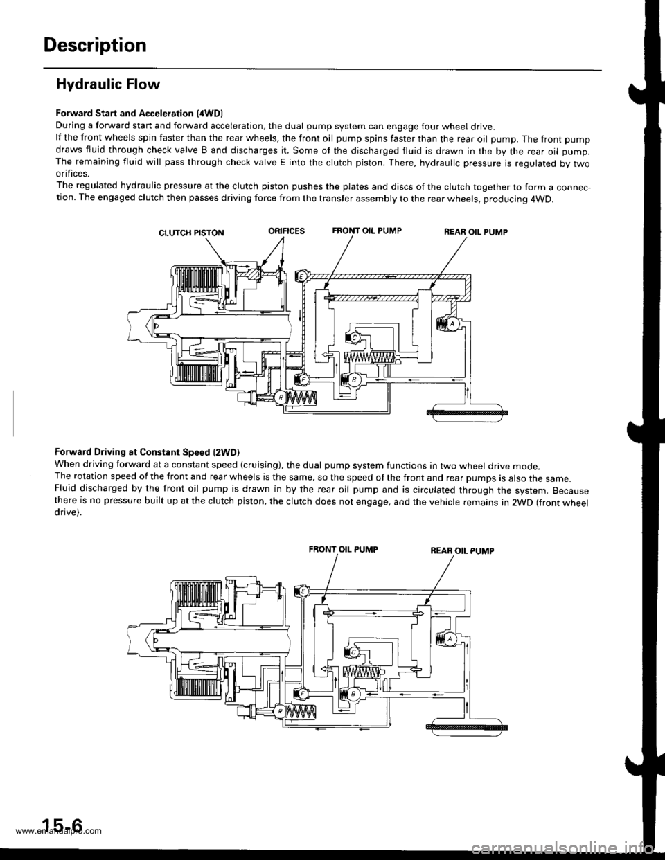
Hydraulic Flow
Forward Start and Acceleration l4WD)During a forward start and forward acceleration, the dual pump system can engage four wheel drive.lf the front wheels spin faster than the rear wheels, the front oil pump spins faster than the rear oil pump. The front pump
draws fluid through check valve B and discharges it. Some of the discharged fluid is drawn in the by the rear oil pump.The remaining fluid will pass through check valve E into the clutch piston. There, hydraulic pressure is regulated by twoorifices.
The regulated hydraulic pressure at the clutch piston pushes the plates and discs of the clutch together to form a connec-tion. The engaged clutch then passes driving force from the transfer assembly to the rear wheels, producing 4WD.
oRrFtcEsFRONT OIL PUMPREAR OIL PUMP
Forward Driving at Constant Speed lzWD)When driving forward at a constant speed (cruising), the dual pump system functions in two wheel drive mode.The rotation speed of the front and rear wheels is the same, so the speed of the front and rear pumps is also the same.Fluid discharged by the front oil pump is drawn in by the rear oil pump and is circulated through the system. Becausethere is no pressure built up at the clutch piston, the clutch does not engage, and the vehicle remains in 2WD (front wheeldrive).
FRONT OIL PUMP
15-6
www.emanualpro.com
Page 797 of 1395
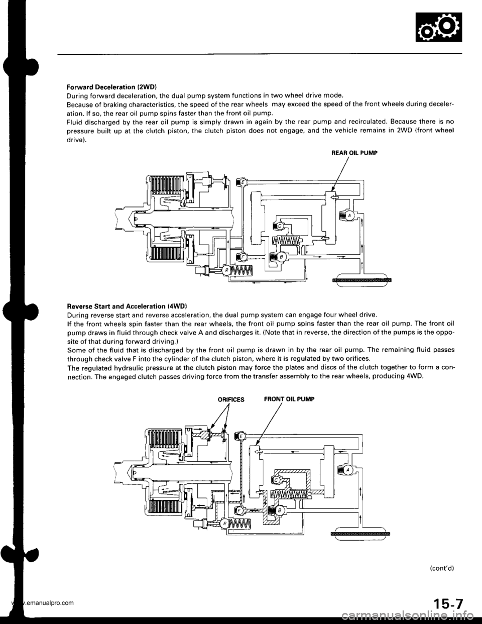
Forward Deceleration l2WDl
During forward deceleration, the dual pump system functions in two wheel drive mode.
Because of braking characteristics, the speed of the rear wheels may exceed the speed ol the front wheels during deceler-
ation. lf so, the rear oil pump spins faster than the front oil pump.
Fluid discharged by the rear oil pump is simply drawn in again by the rear pump and recirculated. Because there is no
pressure built up at the clutch piston. the clutch piston does not engage, and the vehicle remains in 2WD (front wheel
drive).
Reverse Start and Acceleration (4WD)
During reverse start and reverse acceleration, the dual pump system can engage four wheel drive.
lf the front wheels spin faster than the rear wheels, the front oil pump spins faster than the rear oil pump. The front oil
pump draws in fluid through check valve A and discharges it. {Note that in reverse, the direction of the pumps is the oppo-
site of that during forward driving.)
Some of the fluid that is discharged by the front oil pump is drawn in by the rear oil pump. The remaining fluid passes
through check valve F into the cylinder of the clutch piston, where it is regulated by two orifices.
The regulated hydraulic pressure at the clutch piston may force the plates and discs of the clutch together to form a con-
nectlon. The engaged clutch passes driving force from the transfer assembly to the rear wheels, producing 4WD.
oRtFtcEsFRONT OIL PUMP
{cont'd)
15-7
REAR OIL PUMP
www.emanualpro.com
Page 798 of 1395
Description
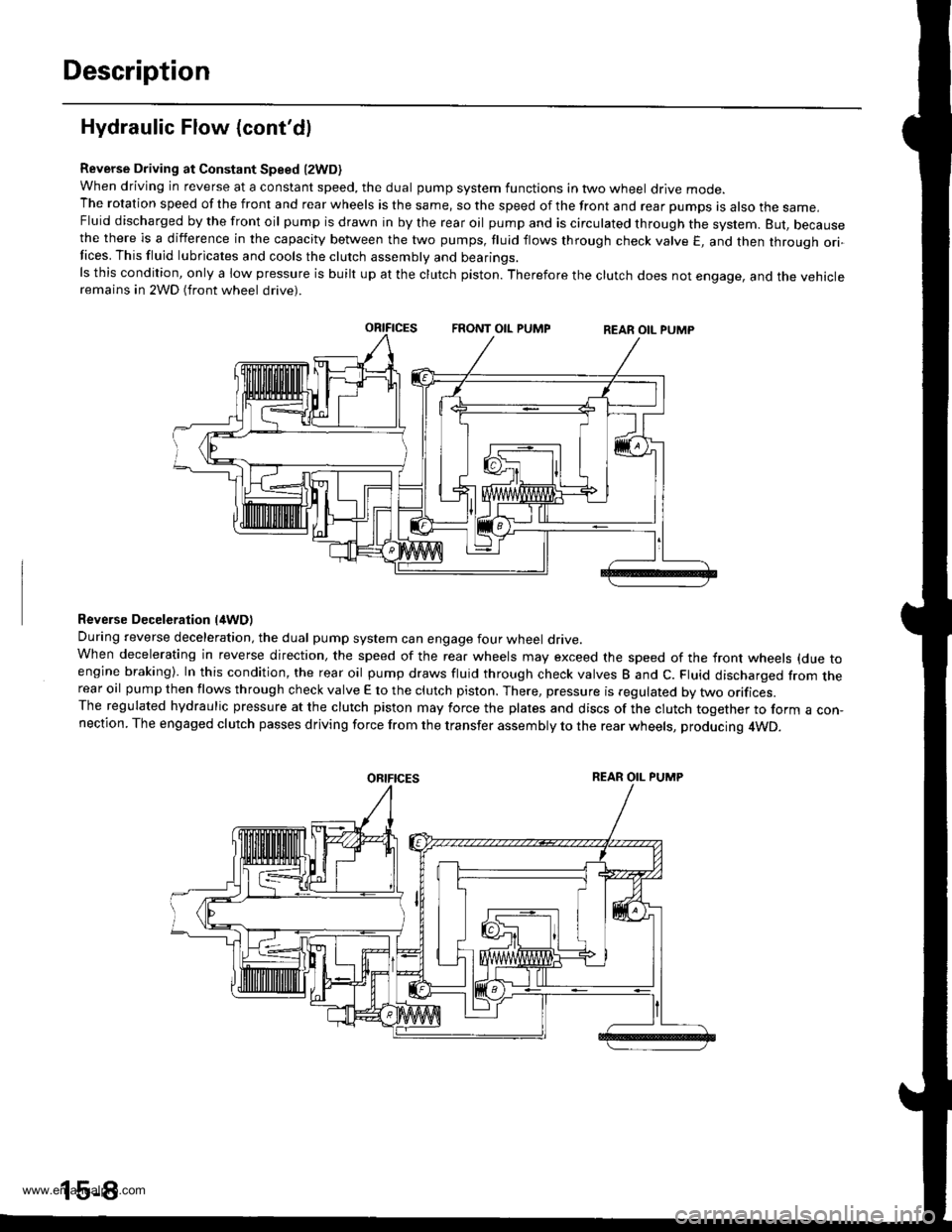
Hydraulic Flow (cont'dl
Reverse Driving at Constant Speed l2WD)when driving in reverse at a constant speed, the dual pump system functions in two wheel drive mode.The rotation speed of the front and rear wheels is the same, so the speed of the front and rear pumps is also the same,Fluid discharged by the front oil pump is drawn in by the rear oil pump and is circulated through the system. But, becausethe there is a difference in the capacity between the two pumps, fluid flows through check valve E, and then through ori-Iices. This fluid lubricates and cools the clutch assembly and bearings.ls this condition, only a low pressure is built up at the clutch piston. Therefore the clutch does not engage, and the vehicleremains in 2WD (front wheel drive).
Reverse Deceleration l/tWDl
During reverse deceleration, the dual pump system can engage four wheel drive.When decelerating in reverse direction, the speed of the rear wheels may exceed the speed of the front wheels (due toengine braking). In this condition, the rear oil pump draws fluid through check valves B and C. Fluid discharged from therear oil pump then flows through check valve E to the clutch piston. There, pressure is regulated by two orifices.The regulated hydraulic pressure at the clutch piston may force the plates and discs of the clutch together to form a con,nection. The engaged clutch passes driving force from the transfer assembly to the rear wheels, producing 4WD.
oRtFtcEsREAR OIL PUMP
www.emanualpro.com
Page 800 of 1395
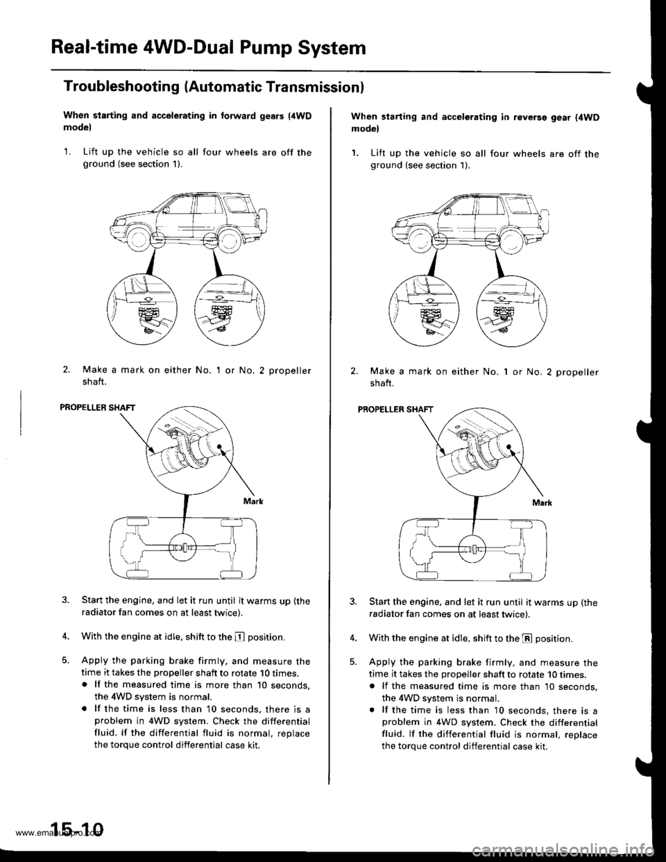
Real-time 4WD-Dual Pump System
Troubleshooting (Automatic Transmissionl
When starting and accelerating in forward gesrs {4WDmodel
1. Lift up the vehicle so all four wheels are off theground (see section 1).
2. Make a mark on either No.
shaft.
'I or No.2 propeller
PROPELLER SHAFT
Start the engine, and let it run until it warms up (the
radiator fan comes on at least twice).
With the engine at idle. shift to the E position.
Apply the parking brake firmly. and measure thetime it takes the propeller shaft to rotate 10 times.. lf the measured time is more than 10 seconds,
the 4WD system is normal.
. lf the time is less than 10 seconds, there is aproblem in 4WD system. Check the differential
fluid. lf the differential fluid is normal, replace
the torque control differential case kit.
15-10
When starting and accelerating in revGrsg gear {4WDmodel
1. Lift up the vehicle so all four wheels are off theground (see section 1).
Make a mark on either No.
shaft.
1 or No. 2 propeller
PROPELLER SHAFT
Start the engine. and let it run until it warms up (the
radiator fan comes on at least twicei.
With the engine at idle, shift to the E position.
Apply the parking brake firmly, and measure the
time it takes the proDeller shaft to rotate 10 times,. lf the measured time is more than 10 seconds,
the 4WD system js normal.. lf the time is less than 10 seconds, there is aproblem in 4WD system. Check the differential
fluid. lf the differential fluid is normal, reolace
the torque control differential case kit.
www.emanualpro.com
Page 802 of 1395
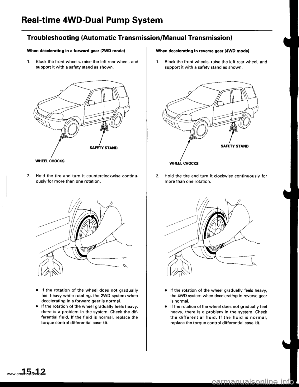
Real-time 4WD-Dual Pump System
Troubleshooting (Automatic Transmission/Manual Transmission)
Whon d6c6l6rating in a torward gear {2WD mode}
1. Block the front wheels, raise the left rear wheel. and
support it with a safety stand as shown.
Hold the tire and turn it counterclockwise continu-
ouslv for more than one rotation.
lf the rotation of the wheel does not gradually
feel heavy while rotating, the 2WD system when
decelerating in a forward gear is normal.
lf the rotation of the wheel gradually feels heavy,
there is a problem in the system. Check the dif-
ferential fluid, lf the fluid is normal, reDlace the
toroue control differential case kit.
WHEEL CHOCKS
15-12
When decelerating in reverse gear (4WD mod€)
1. Block the front wheels. raise the left rear wheel, and
suppo( it with a safety stand as shown.
Hold the tire and turn it clockwise continuouslv for
more than one rotation.
lf the rotation of the wheel gradually feels heaw.
the 4WD system when decelerating in reverse gear
is normal,
lf the rotation of the wheel does not gradually feel
heavy, there is a problem in the system. Check
the differential fluid. lf the fluid is normal.
reolace the torque control differential case kit,
WHEEL CHOCKS
www.emanualpro.com
Page 805 of 1395
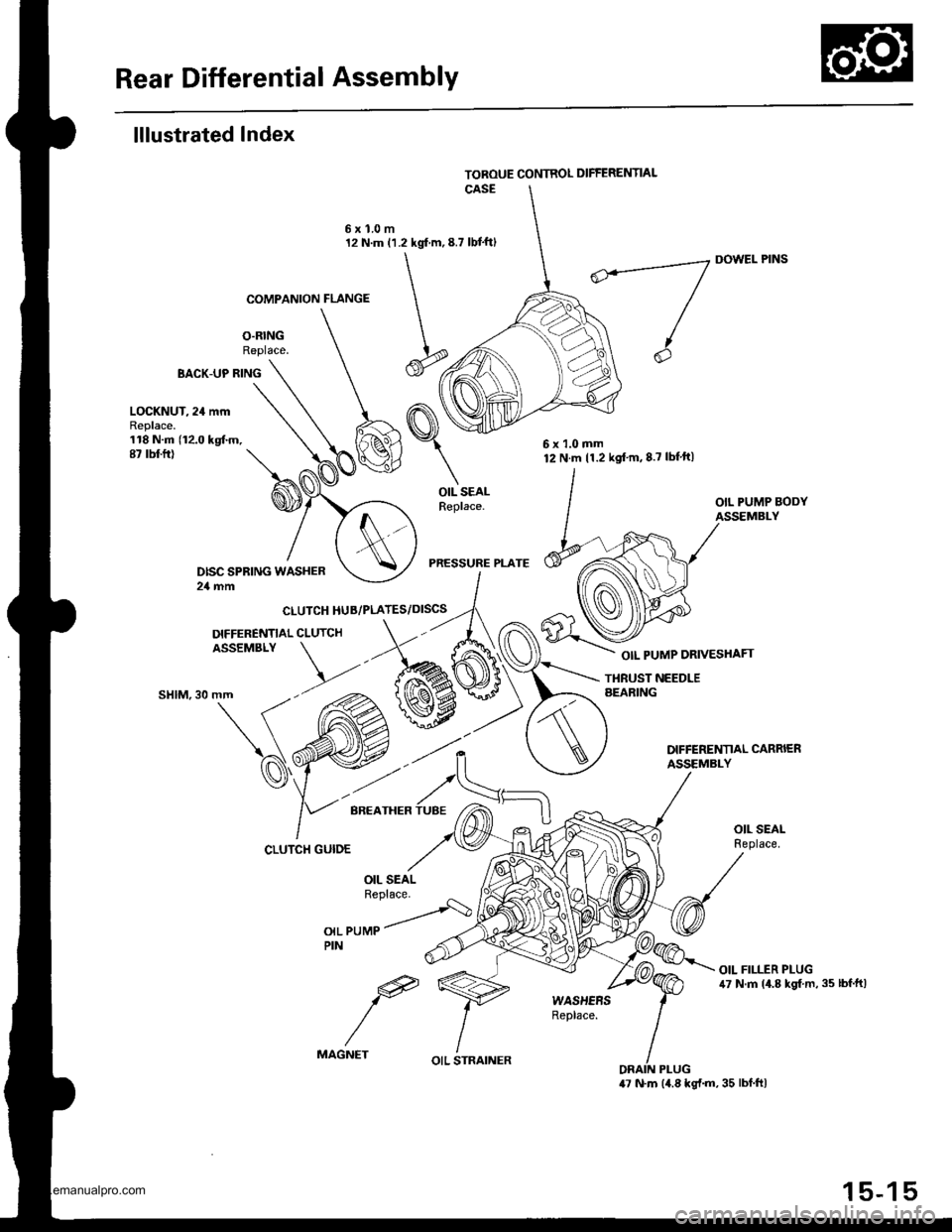
Rear Differential Assembly
lllustrated Index
O.RINGReplace.
6xl.0m12 N.m (1.2 kgf m,8.7 lbt'ftl
BACK-UP RING
COMPANION FLANGE
CLUTCH HUB/PLATES/DISCS
DIFFERENNAL CLUTCHASSEMBLY
DOWEL PINS
OIL PUMP DRIVESHAFT
LOCKNUT, 24 mmReplace.118 N.m (12.0 kgtm.87 rbt ft)
OIL SEALReplace.
PRESSURE PLATE
THBUST NEEDLEAEARING""t",at\(
'd'
CLUTCH GUIDE
OIL PUMPPIN
e
MAGNET
6x1.0mm12 N.m 11.2 kgt'm,8.7 lbf'ft|
OIL STRAINER
15-15
www.emanualpro.com
Page 812 of 1395
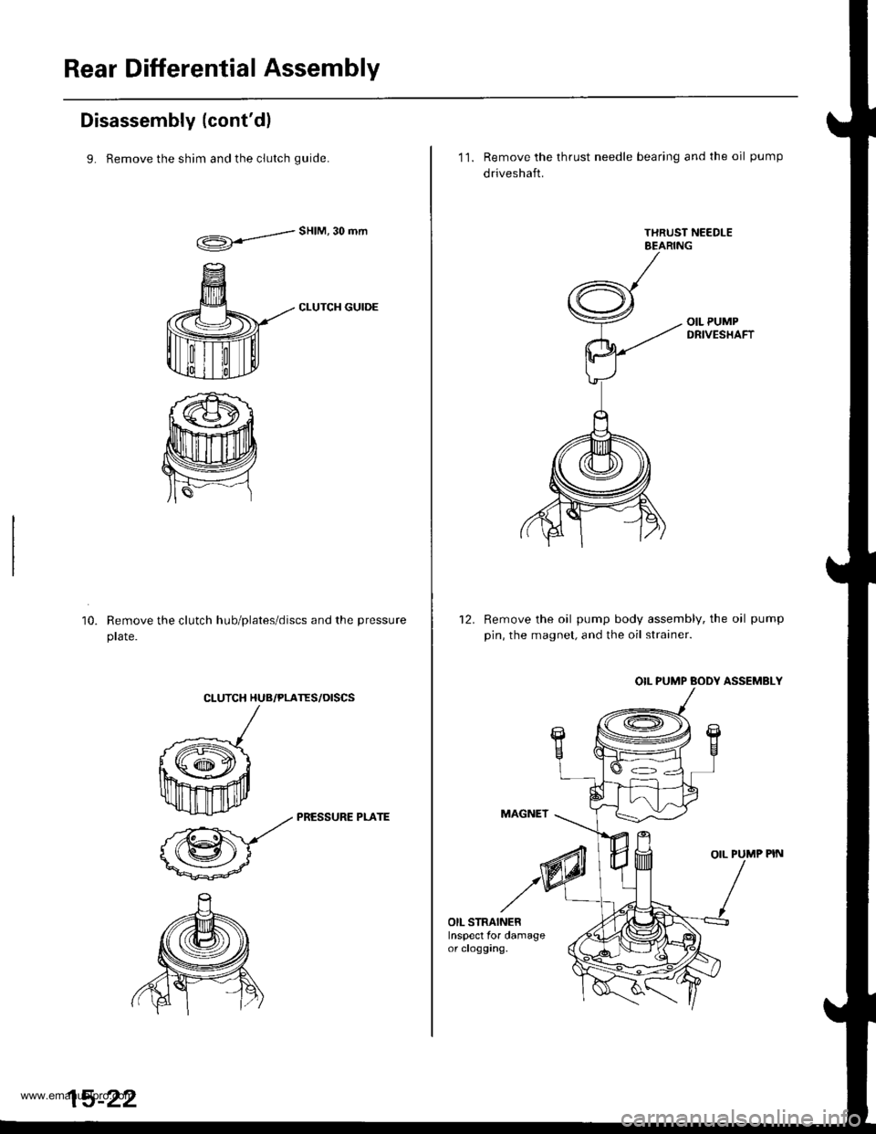
Rear Differential Assembly
Disassembly (cont'dl
9. Remove the shim and the clutch quide.
d"HIM'30mm
CLUTCH GUIDE
Remove the clutch hub/plates/discs and the pressure
prare.
10.
CLUTCH HUB/PLATES/OISCS
k
ffi-:*
_zz PRESSURE PLArE
@-
15-22
11. Remove the thrust needle bearing and the oil pump
driveshaft.
Remove the oil pump body assembly, the oil pump
pin, the magnet, and the oil strainer.
OIL PUMP BODY ASSEMBLY
MAGNET
OIL PUMP PIN
12.
OIL STRAINERInspect for damageor clogging.
www.emanualpro.com
Page 813 of 1395
![HONDA CR-V 1998 RD1-RD3 / 1.G Workshop Manual
Reassembly
1. Apply CVT fluid to the rubber of the oil strainer, then
install the oil strainer, the magnet, and the oil pump
pin to the differential carrier.
OIL PUMP PIN
DIFFERE]TTIAL CARRIERASSEMBL HONDA CR-V 1998 RD1-RD3 / 1.G Workshop Manual
Reassembly
1. Apply CVT fluid to the rubber of the oil strainer, then
install the oil strainer, the magnet, and the oil pump
pin to the differential carrier.
OIL PUMP PIN
DIFFERE]TTIAL CARRIERASSEMBL](/img/13/5778/w960_5778-812.png)
Reassembly
1. Apply CVT fluid to the rubber of the oil strainer, then
install the oil strainer, the magnet, and the oil pump
pin to the differential carrier.
OIL PUMP PIN
DIFFERE]TTIAL CARRIERASSEMBLY
Align the oil pump pin with the groove of the rear oil
pump in the pump body assembly, then install the oil
pump body assembly to the differential carrier assem-
oty.
-n
CWfluid
2.
MAGNET
OIL PUMP BODY ASSEMBLY
3. Tighten the oil pump body assembly mounting
bolts.
4. Install the oil pump driveshaft by aligning the pro-
jection of the oil pump driveshaft with the groove of
the front oil pump in the oil pump body assembly.
lnstall in this direction.
Projection
6x1.0mm12 N.m 11.2 kg{.m,8.7 lbl.ft}
Install the thrust needle bearing.
Install the pressure plate assembly by aligning the
projection of the pressure plate with the groove of
the oil pump driveshaft.
5.
OIL PUMPDRIVESHAFT
(cont'd )
15-23
THRUST NEEDLE BEABING
PRESSURE PLATE
www.emanualpro.com
Page 846 of 1395

Steering
Special Toofs ............. 17-2
Component Locations
Index ................ ....... 17-3
Troubleshooting
General Troubleshooting ................ 1 7-4
Noise and Vibration ......................... 17-8
Fluid Leaks ............. 17-10
Inspection and Adiustment
Steering Operation .......................... 17-12
Power Assist Check
With Vehicle Parked ....................
Steering Linkage and Gearbox .......
Pump Belt
Rack Guide Adjustment ...................
Fluid Rep|acement ...................,,.,....
Pump Pressure Check .................,,...
*Steering Wheel
Removal ................. 17-18
*Steering Column
Removal/lnstallation ................ ....... 17 -2O
lnspection .............. 17-21
Steering Lock Replacement ............ 17 -22
Power Steering Hoses, Lines
Ffuid Leakage Inspection ................. 17 -23
Repfacement .......... 17-23
Power Steering Pump
Repfacement .......... 17-24
Disassembly ...........17-25
fnspection .............. 17-26
Reassembly ............ 17-28
Power Steering Gearbox
Removal ................. 17-31
Disassembly ........... 17-34
Reassembly ............ 17-40
Ball Joint Boot Replacement .......... 17-50
Installation ............. 17-51
17-12
17-13
17-14
l7-15
17-15
17-16
Disassembly/Reassembly............... 17-18
4'%/b.......... -r'-7--a/
SUPPLEN\EN AL RES\RA(N SYSTES{ (SRS\
This model has an SRS which includes a driver's airbag in the steering wheel hub. a passenger's airbag in the dashboardabove the glove box ('97 - 00 models), and seat belt tensioners in the seat belt retractors ('98 - 00 models). Informationnecessary to safely service the SRS is included in this Service Manual. ltems marked with an asterisk (*) on the contentspage include, or are located near, SBS components. Servicing. disassembling or replacing these items will require specialprecautions and tools, and should only be done by an authorized Honda oearer.
To avoid rendering the SRS inoperative, which could lead to peFonal iniury or death in the event of a sevore trontalcollision. allSRS service work must be performod by an authorized Honda dealer.lmproper service procedurgs, including incorrect removal and installalion of the SRS, could lead to personal iniurycaused by unintontional deployment of th€ airbags {'97 - 00 models), and seat belt tensioners ('98 - 00 modelsl.Do not bump the SRS unit. Otherwise, the system may lail in case ot a collision, or the airbags may deploy when theignition switch is ON (lll.
SRS electrical wiring harnesses are identitied by yellow colof coding. Ralated components are located in the steeringcolumn, front console, dashboard, dashboard lower panel, and in the dashboard above the glove box. Do not use elec-trical test equipment on these cilcuits,
www.emanualpro.com