end HONDA CR-V 1998 RD1-RD3 / 1.G Workshop Manual
[x] Cancel search | Manufacturer: HONDA, Model Year: 1998, Model line: CR-V, Model: HONDA CR-V 1998 RD1-RD3 / 1.GPages: 1395, PDF Size: 35.62 MB
Page 852 of 1395
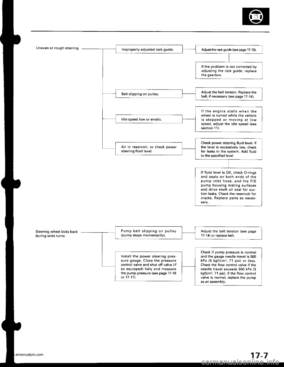
Uneven or rough steering.Ad,ust the rack gu ide (see page 17- 15).
ll the problem is not corrected byadjusting the rack guide, replacethe gearbox.
Adjust the belttension. Replace thebelt, if necessary (see page 17-14).Belt slipping on pulley.
lf the engine stalls when thewheel is turned while the vehicleis stopped or moving at lowspeed, adjust the idle speed (seesection 111.
ldle speed low or erratic.
Check power steering lluid level. lfthe level is excessively low checkfor leaks in the system. Add fluidto the specified level.
Air in reservoir, or check powersteering tluid level.
lf fluid level is OK, check O-ringsand seals on both ends of thepump inlet hose, and the P/Spump housing mating surlacesand drive shaft oil seal for suction leaks. Check the reservoir forcracks, Replace parts as neces-
Pump belt slipping on pulley(pump stops momentarily).Adjust the belt tension (see page17-14) or replace belt.
Check if pump pressure is normaland the gauge needle travel is 500kPa (5 kgl/cm,, 71 psi) or less.Check the flow control valve if theneedle travel exceeds 500 kPa (5kgflcm', 71 psi). lI the flow controlvalve is normal, replace the pumpas an assembly,
Install the power steering pres-sure gauge, Close the pressurecontrol valve and shut off valve (if
so equipped) fully and measurethe pump pressure (see page 17-16ot 17 17).
Steering wheel kicks backduring wide turns.
7-7
www.emanualpro.com
Page 855 of 1395
Troubleshooting
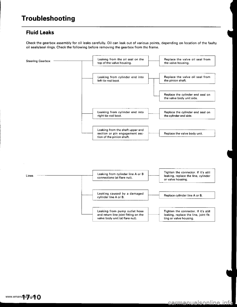
Fluid Leaks
Check the gearbox assembly for oil leaks carefully. Oil can leak out ot various points, depending on location of the faulty
oil seals/seal rings. Check the following before removing the gearbox from the frame.
Steering GearboxLeaking from the oil seal on thetop of the valve housing.Replace the valve oil seal fromthe valve housing.
Leaking from cylinder end intoleft tie rod boot.Replace the valve oil seal fromthe pinion shaft.
Replace the cylinder end seal onthe valve body unit side.
Leaking from cylinder end intoright tie-rod boot.Replace the cylinder end seal onthe cylinder end side.
Leaking lrom the shaft upper endsection or pin engagement sec-tion of the pinion shaft.Replace the valve body unit.
Tighten the connector. It it's stillleaking, replace the line, cylinderor valve housing.
Leaking from cylinder line A or Bconnections (at tlare nut).
Leaking caused by a damagedcylinder line A or B.Replace cylinder line A or B.
Leaking from pump outlet hoseand return line joint fitting on thevalve body unit {at tlare nut}.
Tighten the connector. ll it's stillleaking, replace the line, joint fit-ting or valve housing,
17-10
www.emanualpro.com
Page 858 of 1395
Steering Linkage and Gearbox
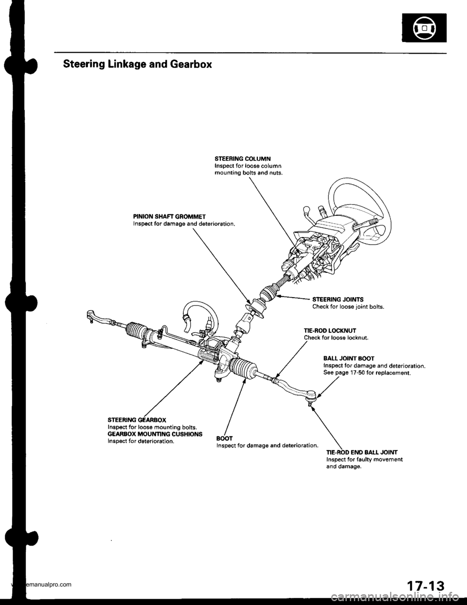
PINION SHAFT GROMMETInspoct for damage and deterioration.
STEERING JOINTSCheck for loose joint bolts.
NE-ROD LOCKNUTCheck Ior loose locknut.
Inspect for loose mounting bolts.GEARBOX MOUNTING CUSHIONSlnsp6ct for dgterioration.BOOTlnspect for damag€ and d€terioration.
BALL JONT AOOTInspoct lor damage and deterioration.S€e page 17-50 for replacemont.
END AAtL JOINTInspect for faulty movementano oamag€.
17-13
www.emanualpro.com
Page 860 of 1395
Rack Guide Adjustment
1.
6.
7.
5.
4.
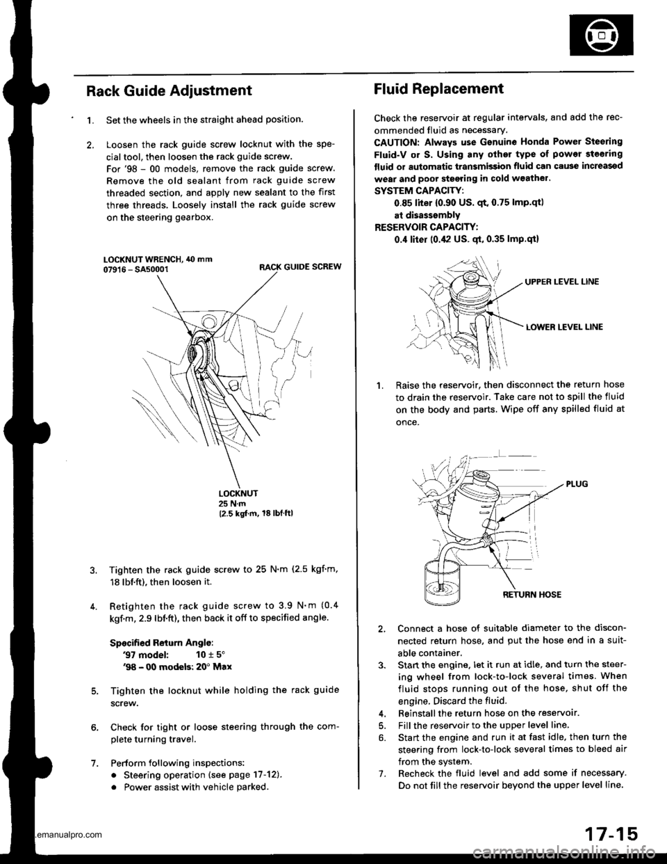
Set the wheels in the straight ahead position.
Loosen the rack guide screw locknut with the spe-
cialtool, then loosen the rack guide screw.
For'98 - 00 models, remove the rack guide screw.
Remove the old sealant from rack guide screw
threaded section, and apply new sealant to the first
three threads. Loosely install the rack guide screw
on the steering gearbox.
RACK GUIDE SCREW
LOCKNUT25 N.m
12.5 kgt m, 18lbtftl
Tighten the rack guide screw to 25 N.m (2.5 kgf'm,
18 lbf.ft), then loosen it.
Retighten the rack guide screw to 3.9 N'm (0.4
kgf.m, 2.9 lbf.ft), then back it off to specified angle.
Specified Return Anglo:
37 model: 10 r 5"'98 - 00 modeb: 20' Max
Tighten the locknut while holding the rack guide
screw.
Check for tight or loose steering through the com-
plete turning travel.
Perform following inspections:
. Steering operation (see page 17-12).
. Power assist with vehicle parked
Fluid Replacement
Check the reseryoir at regular intervals, and add the rec-
ommended fluid as necessary.
CAUTION: Always use Gsnuine Honda Power Steering
Fluid-V or S. Using any other type of power steering
tluid or automatic transmission fluid can cause increassd
wear and poor steering in cold w3athel.
SYSTEM CAPACITY:
0.85 liter {0.90 US. qt. 0.75 lmp.qtl
at disasssmbly
RESERVOIR CAPACITY:
0.,1 liter (0.42 US. gt, 0.35 lmp.qi)
UPPEN LEVEL LINE
LOWER LEVEL LINE
1.Raise the reservoir. then disconnect the return hose
to drain the reservoir. Take care not to spill the fluid
on the body and parts. Wipe off any spilled fluid at
once.
2, Connect a hose of suitable diameter to the discon-
nected return hose, and put the hose end in a suit-
able container.
3. Stan the engine. let it run at idle, and turn the steer-
ing wheel from lock-to-lock several times. When
fluid stops running out of the hose, shut off the
engine. Discard the fluid.
4. Beinstallthe return hose on the reservoar.
5. Fill the reservoir to the upper level line,
6. Start the engine and run it at fast idle. then turn the
steering from lock-to-lock several times to bleed air
from the system.
7. Recheck the fluid level and add some if necessary.
Do not fill the reservoir beyond the upper level line.
www.emanualpro.com
Page 866 of 1395
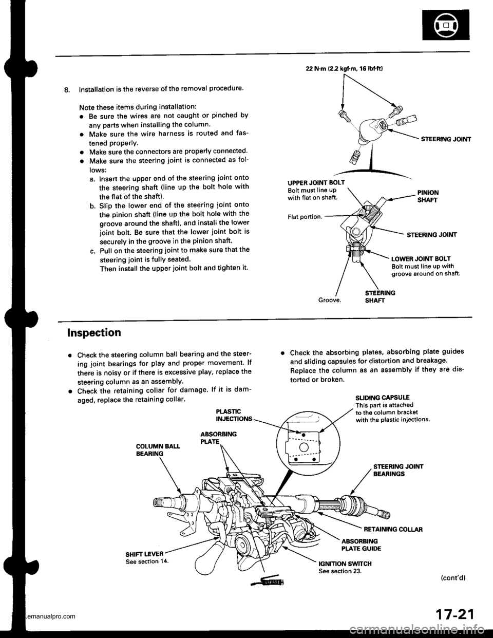
8. Installation is the reverse ofthe removal procedure.
Note these items during installation:
. Be sure the wires are not caught or pinched by
any parts when installing the column.
a Make sure the wire harness is routed and fas-
tened properly.
. Make sure the connectors are properly connected.
. Make sure the steering joint is connected as fol-
lows:
a. lnsert the uDper end of the steering joint onto
the steering shaft (line up the bolt hole with
the flat ot the shaft).
b. Slip the lower end of the steering ioint onto
the Dinion shaft (lins up the bolt hole with the
groove around the shaft). and installthe lower
ioint bolt. Be sure that the lower joint bolt is
securely in the groove in the pinion shaft'
c. Pull on the steering joint to make sure that the
steering joint is JullY seated.
Then install the upper joint bolt and tighten it.
22 N.m (2.2 kgf.m, 16lbt.ftl
UPPER JOINT BOLT
Bolt must Iine uPwith fl6t on shaft.
Flat ponion.
SIEERING JOIMT
STECRING JOINT
LOWER JOINT BOLTBolt must line up withgroove around on shaft,
Inspection
Check the steering column ball bearing and the steer-
ing joint bearings for play and proper movement. lf
there is noisy or if there is excessive play, replace the
steering column as an assemblY
Check the retaining collar for damage. lf it is dam-
aged, replace the retaining collar.
PLASl'tCINJECTIONS
ABSOBBINGPLATE
SHIFT I.EVER
. Check the absorbing plates, absorbing plate guides
and sliding capsules Jor distortion and breakage.
ReDlace the column as an assembly if they are dis-
torted or broken.
SLIDING CAPSUIIThis part is attachedto the column bracketwith the plastic injections.
FETAINING COLLAR
ABSORBINGPLATE GUIDE
|GNMON SWTTCHSee section 23.(cont'd)
17-21
See section 14.
www.emanualpro.com
Page 867 of 1395
Steering Column
Inspection (cont'dl
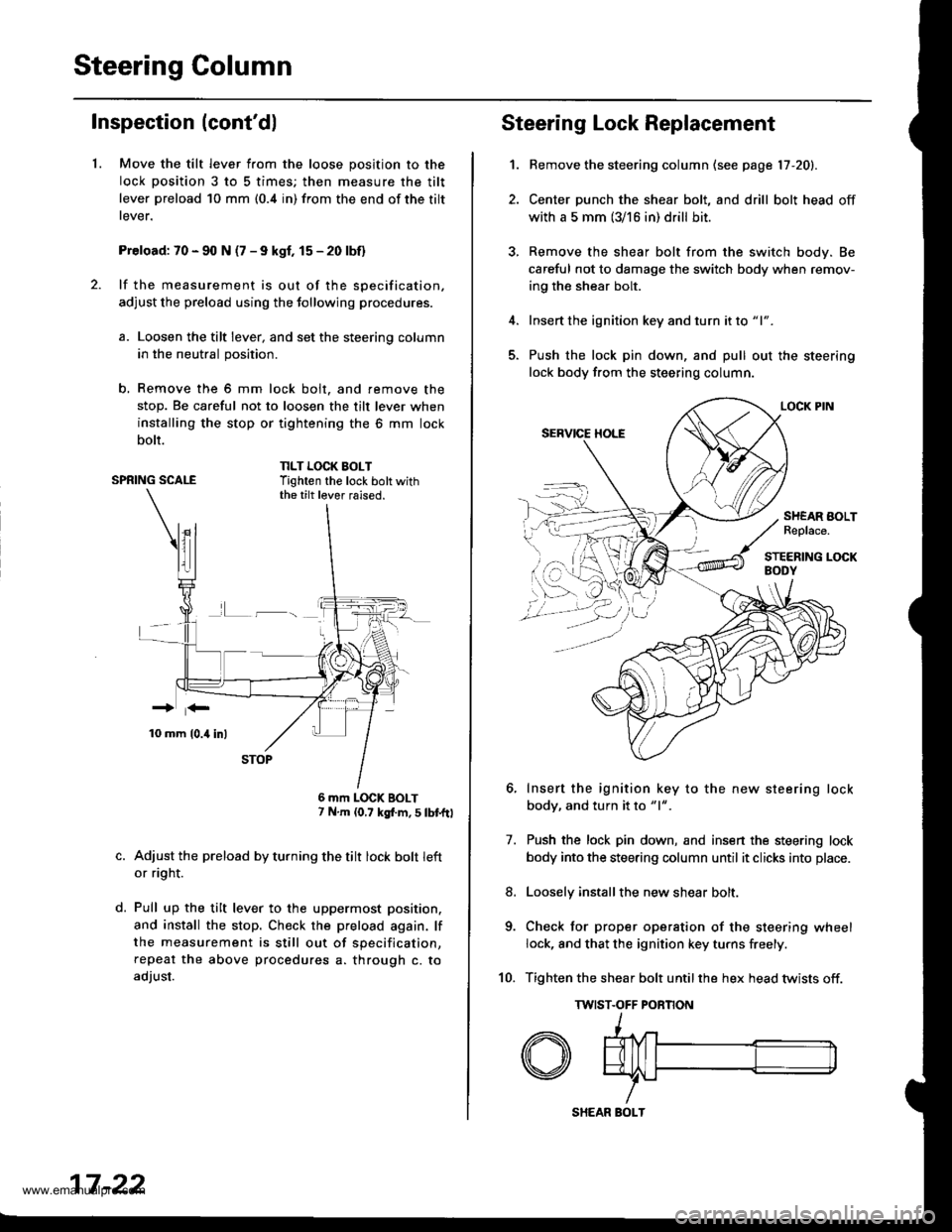
1.Move the tilt lever from the loose position to the
lock position 3 to 5 times; then measure the tilt
lever preload 10 mm (0.4 in) from the end of the tilt
rever.
Preload: 70 - 90 N (7 - 9 kgf, 15 - 20 lbf)
lf the measurement is out of the specification.
adjust the preload using the tollowing procedures.
a. Loosen the tilt lever, and set the steering column
in the neutral position.
b, Remove the 6 mm lock bolt. and remove the
stop. Be careful not to loosen the tilt lever when
installing the stop or tightening the 6 mm lock
bolt.
SPRING SCALENLT LOCK BOLTTighten the lock bolt withthe tilt lever raised.
L-_
d.
6 mm LOCK BOLT7 N.m (0,7 kgf.m, S tbtftl
Adjust the preload by turning the tilt lock bolt left
or ri9ht.
Pull up the tilt lever to the uppermost position.
and install the stop. Check the preload again. lf
the measurement is still out of specification,
repeat the above procedures a. through c. to
adjust.
17 -22
SHEAR BOLT
Steering Lock Replacement
1.
7.
Bemove the steering column (see page 17 -20).
Center punch the shear bolt, and drill bolt head off
with a 5 mm (3/16 in) drill bit.
Remove the shear bolt from the switch body. Be
careful not to damage the switch body when remov-
ing the shear bolt.
Insert the ignition key and turn it to "1".
Push the lock pin down, and pull out the steering
lock body from the steering column.
Insert the ignition key to the new steering lock
body, and turn it to "1".
Push the lock pin down, and insen the steering lock
body into the steering column until it clicks into place.
Loosely installthe new shear bolt.
Check tor proper operation of the steering wheel
lock, and that the ignition key turns freely.
Tighten the shear bolt untilthe hex head twists off.
TWIST.OFF PORNON
8.
10.
SHEAR BOLTReplace.
www.emanualpro.com
Page 868 of 1395
Power Steering Hoses, Lines
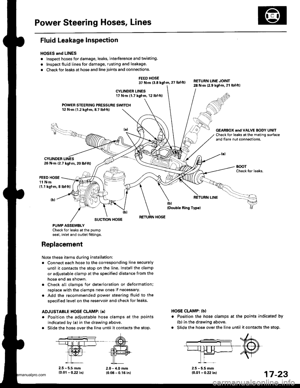
Fluid Leakage Inspection
HOSES and LINES
. lnspect hoses for damage. leaks. interference and twisting
. Inspect fluid linesfor damage, rusting and leakage.
. Check for leaks at hose and line joints and connections.
FEED HOSE37 N.m 13.8 kgf.m, 27 lbtft)RETURN LINE JOINT28 N.m (2.9 kgf.m.21 lbf.ftl
CYLINDER LINES17 N.m (1.7 kgf.m. 12 lbf.ftl
FOWER STEERING PRESSURE SWITCH12 N.m (1.2 kgf.m,8.7 lbtft)
26 N.m (2.7 kgf.m, 20 lbf.ft)
GEARBOX .nd VALVE BODY UNllCheck for leaks at the mating surfaceand flare nut connections.
CYLINDER
FEED HOSE11 N.m('1.1 kgt.m, 8 lbf.ftl
SUCTION HOSE
PUMP ASSEMBLYCheck for leaks atthe pump
seal. inlet and outlet fittings.
Note these items during installation:
. Connect each hose to the corresponding line securely
until it contacts the stop on the line. Install the clamp
or adjustable clamp at the specified distance from the
hose end as shown.
. Check all clamDs for deterioration or deformation;
replace with the clamps new ones if necessary.
. Add the recommended power steering fluid to the
specified level on the reservoir and check for leaks.
ADJUSTABLE HOSE CLAMP: la)
. Position the adjustable hose clamps at the points
indicated by (a) in the drawing above.
. Slide the hose over the line until it contacts the stop.
HOSE CLAMP: lbl
. Position the hose clamps at the
(b) in the drawing above.
. Slide the hose over the line until
Replacement
10.01 - 0.22 in)
points indicatsd by
it contacts the stop,
2.0 - 4.0 mm10.08 - 0.16 inl2.5 - 5.5 mm{0.01 - 0.22 in}17 -23
www.emanualpro.com
Page 870 of 1395
Disassembly
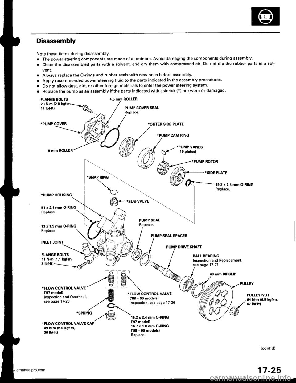
Note these items during disassembly:
. The power steering components are made of aluminum, Avoid damaging the components during assembly.
. Clean the disassembled parts with a solvent, and dry them with compressed air. Do not dip the rubber parts in a sol-
vent.
. Always replace the O-rings and rubber seals with new ones before assembly.
. Apply recommended power steering fluid to the parts indicated in the assembly procedures.
. Do not allow dust, dirt, or other foreign materials to enter the power steering system.
. Replace the pump as an assemblyif the parts indicated with asterisk(*) areworn ordamaged.
FLANGE BOLTS20 N.m 12.0 kgt'm,
1a tbf,ft)
.PUMP COVER
ROLLER
PUMP COVER SEAL
*PUMP HOUSING
5l x 2.4 mm O-RINGRepiace.
13 x 1.9 mm O-RINGReplace.
INLET JOINT
*OUTER SIDE PLATE
.PUMP CAM RING
PUMP SEAL SPACER
PUMP DRIVE SHAFT
FLANGE BOLTS11 N.m 11.1 kgt m,8 tbf.ft)
PULI.-EY NUTfl N.m (6.5 kgf.m,/r7 lbf.ftl
(cont'd)
17 -25
www.emanualpro.com
Page 871 of 1395
Power Steering Pump
Disassembly (cont'dl
1.
7.
9.
10.
Drain the fluid from the pump.
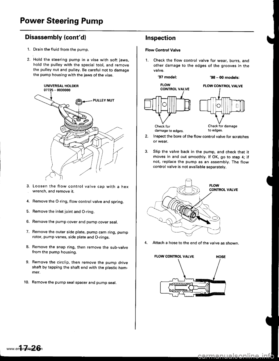
Hold the steering pump in a vise with soft jaws.
hold the pulley with the special tool, and remove
the pulley nut and pulley. Be careful not to damagethe pump housing with the jaws of the vise.
UNIVERSAL HOLDER07725 - 0030000
Loosen the flow control valve cap with a hexwrench, and remove it.
Remove the O,ring, flow control valve and spring.
Remove the inlet joint and O-ring.
Remove the pump cover and pump cover seal.
Remove the outer side plate, pump cam ring, pump
rotor, pump vanes, side plate and O-rings.
Remove the snap ring, then remove the sub-valvefrom the pump housing.
Remove the circlip, then remove the pump driveshaft by tapping the shaft end with the ptastic ham-mer.
Remove the pump seal spacer and pump seal.
17-26
Inspection
Flow Control Valve
1. Check the flow control valve for wear, burrs, and
other damage to the edges of the grooves in thevalve.
'97 model:
FLOWCONTROL VALVE
Check fordamage to edges.
'98 - 0O mod€ls:
FLOW CONTBOL VALVE
Check for damageto edges.
Insp€d the bore of the flow control valve tor scratchesor wear.
Slip the valve back in the pump, and check that itmoves in and out smoothly. lf OK, go to step 4; ifnot, replace the pump as an assembly. The flowcontrolvalve is not available separately.
CONTROL VALVE
4. Attach a hose to the end of the valve as shown.
FLOW CONTROL VALVE HOSE
www.emanualpro.com
Page 872 of 1395
5. Submerge the valve in a container of power steer-
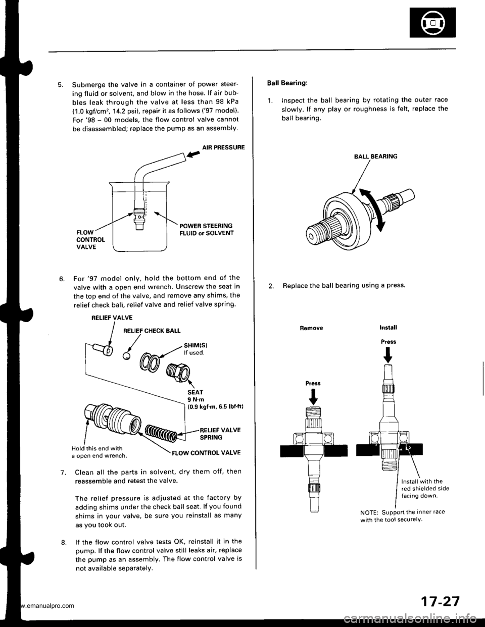
ing fluid or solvent, and blow in the hose. lf air bub-
bles leak through the valve at less than 98 kPa
(1.0 kgflcm', 14.2 psi), repair it as follows ('97 model).
For'98 - 00 models, the flow control valve cannot
be disassembled; replace the pump as an assembly
AIR PRESSURE
POWER STEENINGFLUID or SOLVENT
6.For'97 model only, hold the bottom end of the
valve with a open end wrench. Unscrew the seat in
the top end of the valve, and remove any shims, the
reliel check ball, relief valve and relief valve spring.
RELIEFALVE
RELIEF CHECK BALL
{w@r
7.
SEAT9 N.m(0.9 kgf.m, 6.5 lbfft)
RELIEF VALVESPRING
FLOW CONTBOL VALVE
Clean all the parts in solvent, dry them otf, then
reassemble and retest the valve.
The relief pressure is adjusted at the factory by
adding shims under the check ball seat lf you found
shims in your valve, be sure you reinstall as many
as you took out.
lf the flow control valve tests OK, reinstall it in the
pump. It the flow control valve still leaks air, replace
the pump as an assembly. The flow control valve is
not available separately.
8,
Hold this end witha open eno wrencn.
Ball Bearing:
'1. Inspect the ball bearing by rotating the outer race
slowly. lf any play or roughness is felt, replace the
ball bearing.
2. Replace the ball bearing using a press.
Removelnstall
Press
I
Press
I
lnstall with thered shaelded sidefacing down.
NOTEr SuPPort the inner race
with the tool securelY-
BALL EEARING
17-27
www.emanualpro.com