end HONDA CR-V 1998 RD1-RD3 / 1.G Workshop Manual
[x] Cancel search | Manufacturer: HONDA, Model Year: 1998, Model line: CR-V, Model: HONDA CR-V 1998 RD1-RD3 / 1.GPages: 1395, PDF Size: 35.62 MB
Page 938 of 1395
Master Cylinder
I nspection/Disassembly
CAUTION: Do not spill brake fluid onthe vehicle; it may
damsge the paint; il brake fluid does contact th6 paint.
wash it off immodiately with water.
NOTE:
. Before reassembling, check that all parts are free of
dust and other foreign particles.
. Do not try to disassemble the master cylinder assem-
bly. Replace the master cylinder assembly with a new
pan it necessary,
. Make sure no dirt or other foreign matter is allowed
to contaminate the brake fluid.
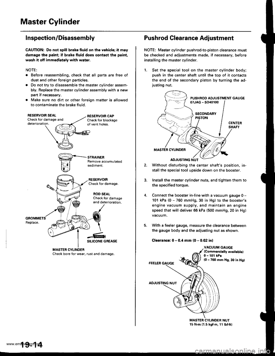
RESERVOIR SEALCheck for damaoe anddeterioration,
RESERVOIRCheck for damage.
ROD SEALCheck for damageand deterioration.
-€-1SILICONE GREASE
MASTER CYLINOERCheck bore for wear, rust and damage.
19-14
Pushrod Clearance Adjustment
NOTE: Master cylinder pushrod-to-piston clearance must
be checked and adjustments made, if necessary. before
installing the master cylinder.
1. Set the special tool on the master cylinder body;
push in the center shaft until the top ot it contacts
the end of the secondary piston by turning the ad-justing nut.
PUSHROD ADJUSTMENT GAUGE07JAG - SD{o100
SECONDARY
MASTER CYLINDER
ADJUSTING NUT
Without disturbing the center shaft's position, in-
stallthe special tool upside down on the booster.
Install the master cylinder nuts, and tighten them to
the sDecified toroue.
Connect the booster iniine with a vacuum gauge 0 -
101 kPa (0 - 760 mmHg, 30 in Hg) to the booster's
engine vacuum supply, and maintain an engine
speed that will deliver 66 kPa (500 mmH9, 20 in Hg)
vacuum.
With a feeler gauge, measure the clearance between
the gauge body and the adiusting nut as shown.
Clearanco: 0 - 0.4 mm (0 - 0.02 inl
VACUUM GAUGElCommo.cidly 6vailablcl0 - 101 kPtl0 - 760 mm Hg, 30 in Hgl
MASTER CYLINDER NUT15 N.m 11.5 kgt m, 11 lbt.ftl
www.emanualpro.com
Page 943 of 1395
10.
11,
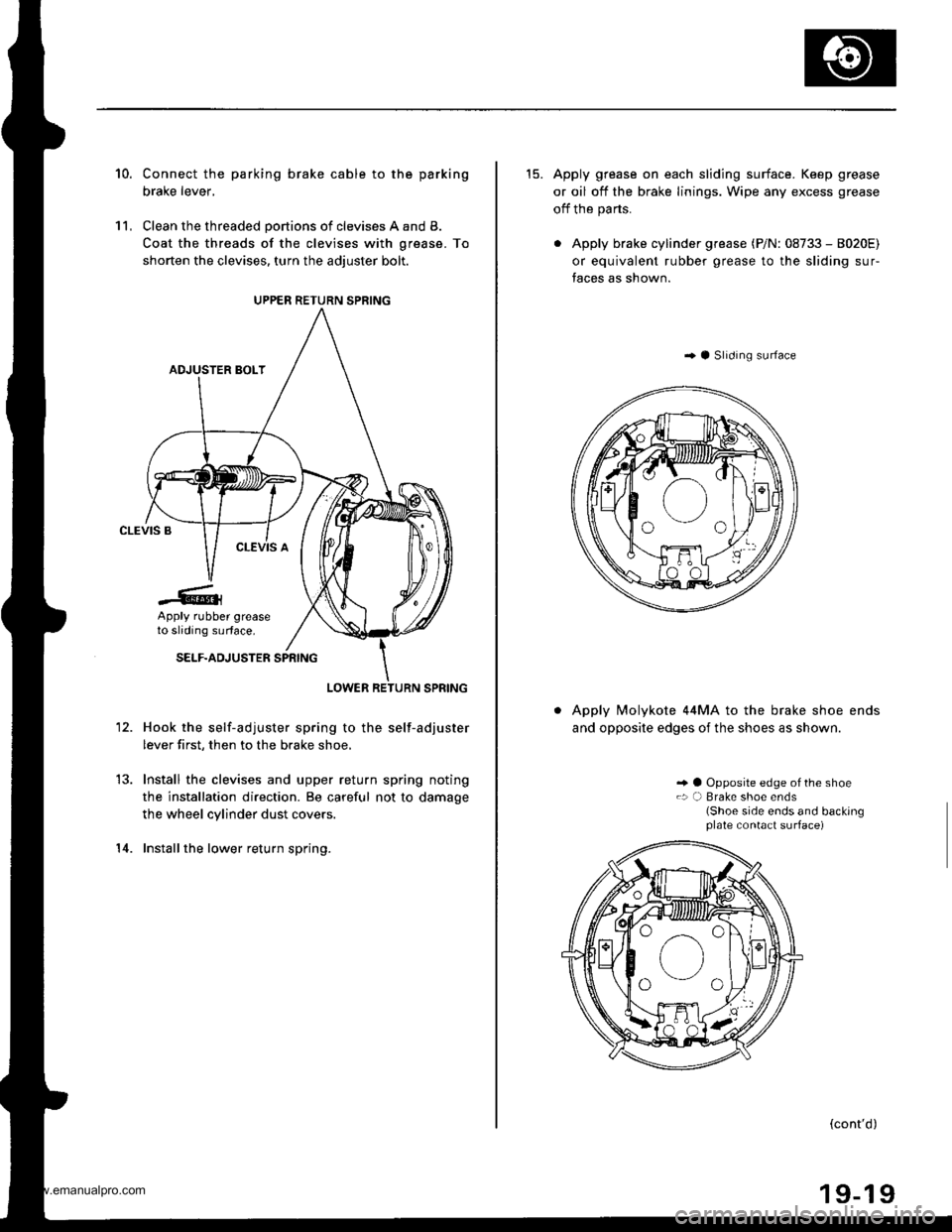
Connect the parking brake cable to the parking
brake lever,
Clean the threaded portions of clevises A and B.
Coat the threads of the clevises with grease. To
shorten the clevises, turn the adiuster bolt.
Hook the self-adjuster spring to the self-adjuster
lever first, then to the brake shoe,
Install the clevises and upper return spring noting
the installation direction. Be careful not to damage
the wheel cylinder dust covers.
Installthe lower return spring.
12.
14.
UPPER RETURN SPRING
Apply rubber greaseto sliding surface.
15. Apply grease on each sliding surface. Keep grease
or oil off the brake linings. Wipe any excess grease
off the parts.
. Apply brake cylinder grease (P/N: 08733 - 8020E)
or equivalent rubber grease to the sliding sur-
faces as shown.
..4 Slrdrng surface
Apply Molykote 44MA to the brake shoe ends
and opposite edges of the shoes as shown.
.. a Opposite edge of the shoe.: a) Brake shoe ends(Shoe side ends and backingplate contact surface)
(cont'd)
www.emanualpro.com
Page 953 of 1395
Anti-lock Brake System (ABS)
Features/Gonstruction (cont'd)
ABS Modulator
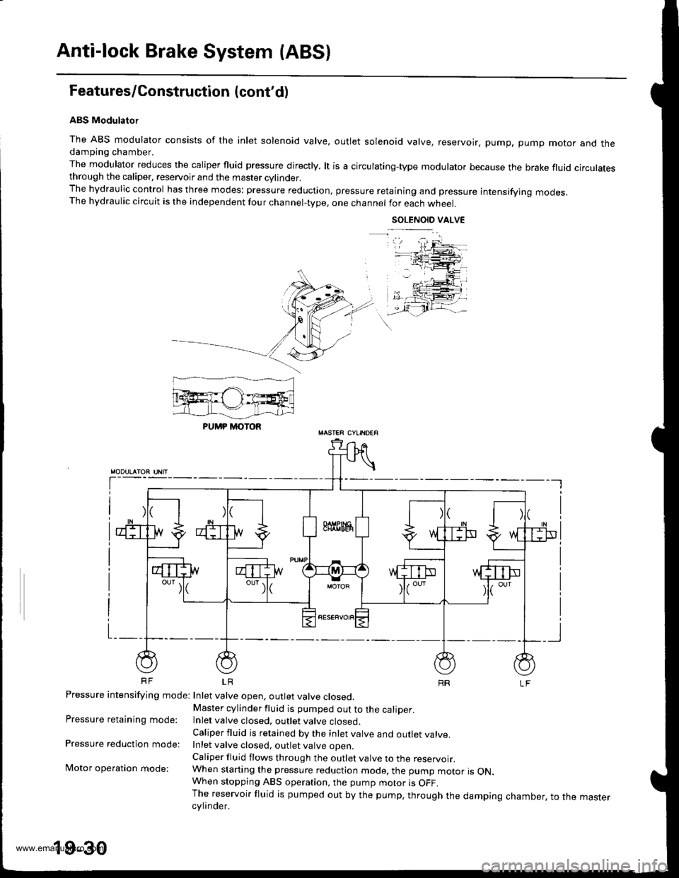
The ABS modulator consists of the inlet solenoid valve, outlet solenoid valve, reservoir, pump, pump motor and thedampjng chamber.
The modulator reduces the caliper fluid pressure directly. lt is a circulating-type modulator because the brake fluid circulatesthrough the caliper, reservoir and the master cylinder.The hydraulic control has three modes: pressure reduction, pressure retaining and pressure intensifying modes.The hydraulic circuit is the independent four channel-type, one channel for each wheel.
SOLENOID VALVE
t-
Pressure intensifying mode: Inlet valve open, outlet valve closed,
Pressure retaining mode:
Pressure reduction mode:
Motor operation mode:
Master cylinder fluid is pumped out to the caliper.Inlet valve closed, outlet valve closed.
Caliper fluid is retained by the inlet valve and outlet valve.Inlet valve closed, outlet valve ooen
Caliper fluid flows through the outlet valve to the reservoir.When starting the pressure reduction mode. the pump motor is ON.When stopping ABS operation, the pump motor is OFF.The reservoir fluid is pumped out by the pump, through the damping chamber, to the mastercylinder.
PUMP MOTOR
19-30
www.emanualpro.com
Page 959 of 1395
Troubleshooting Precautions
ABS lndicalor
1 lf the system is oK, the ABS indicator goes off two seconds after turning the ignition switch oN 1l) wathout staningthe engine, and then comes on again and goes off after two seconds. This occurs because the ABS control unit isturned on by the lG2 power source.2. The ABS indicator comes on when the ABS control unit detects a problem in the system. However, even thouoh thesystem is operating properly, the ABs indicator will come on too, under the following conditions:. Signal disturbance
. Wheel spin
. Only drive wheels rotate. Battery voltage fluctuates
To determine the actual cause of the problem, question the customer about the problem, taking these conditions intoconsideration:
3 When a problem is detected and the ABS indicator comes on, the indicator can stay on until the ignition switch isturned OFF, or it can automatically go off, depending on the mode.. Indicator stays on untilthe ignition switch is turned off: When the system is in the system down mode.. Indicator automatically goes off: When the system is in the control inhibition mode.4 The ABS indicator stays on when the system is reactivated without erasing the DTC, but it goes off after starting thevehicle.
When the wheel sensor system is faulty and the ABS indicator comes on. the algorithm of the system automatically turnsoff the ABS indicator after the wheel speed signal returns to the normal speed. Also, when the DTc is erased, the cpu isreset and the ABS indicator goes off when the system checked out normal by the initial diagnosis.Therefore, test-drive the vehicle after servicing the wheel sensor system. and be sure that the ABS indicator does notcome on.
5 When the ABS control unit outputs battery voltage to the gauge assembly, the ABS indicator ooes off.
Diagnostic Trouble Code (DTCI
1. The diagnostic trouble code (DTc) is memorized when a problem is detected and the ABS indicator does not go off,or when the ABS indicator comes on.The DTc is not memorized when the ABS indicator comes on unress the cpu is activated,2 The memory can hold any number of DTCs. However, when the same DTc is detected twice or more, the tater one iswritten over the old one.
Therefore, when the same problem is detected repeatedly, it is recorded as one DTC.3. The DTCs are indicated in the order of ascending number, not in the order they occur.4. The DTCS are memorized in the EEPROM (non-volatile memorv).Therefore, the memorized DTcs cannot be canceled by disconnecting the battery. perform the specified procedures toerase the DTCS.
Self-diagnosis
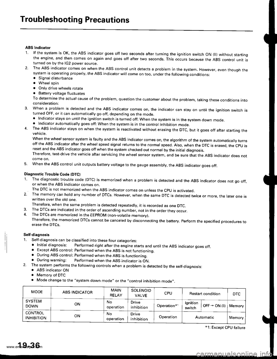
1. Self-diagnosis can be classified into these four categories:' Initial diagnosis: Performed right after the eng ine starts and untir theABS indicator goes off.. Except ABS control: Performed when the ABS is not functioning.. During ABS control: Performed when the ABS is functioning.. During warning: Performed when the ABS indicator is ON.2. The system performs the fo|owing contrors when a probrem is detected by the serf-diagnosis:. ABS indicator ON. Memorv of DTC. Mode changetothe "system down mode,, or the ,,control inhibition mode,,.
MODEABS INDICATORMAIN
RELAY
SOLENOID
VALVECPURestart conditionDTC
SYSTEM
DOWNONNo
operation
Drive
inhibitionOperation*rlgnition
switchoFF - ON l)Memory
CONTROL
INHIBITIONONNo
operal|on
Drive
inhibitionOperationAutomaticlMemory
*1: Except CPU failure
19-36
www.emanualpro.com
Page 979 of 1395
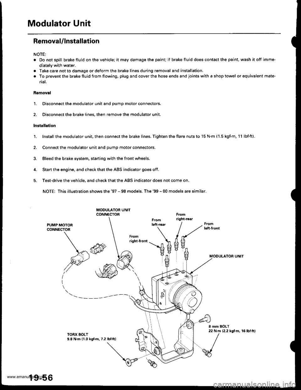
Modulator Unit
Removal/lnstallation
NOTE:
. Do not spill brake fluid on the vehicle; it may damage the painu if brake fluid does contact the paint, wash it off imme-
diately with water.
a Take care not to damage or deform the brake lines during removal and installation.
. To prevent the brakefluidfrom flowing, plug and coverthe hose ends and joints with a shop towel or equivalent mate-
rial,
Romoval
1. Disconnect the modulator unit and Dump motor connectors.
2. Disconnect the brake lines, then remove the modulator unit.
lnstallation
1. Install the modu lator u nit. then con nect the brake lines. Tighten the flare nuts to 15 N.m ( 1.5 kgf.m, 1 1 lbf.ft).
2. Connect the modulator unit and oumo motor connectors.
3. Bleed the brake system, staning with the front wheels.
4. Start the engine, and check that the ABS indicator goes off.
5. Test-drive the vehicle, and check that the ABS indicator does not come on,
NOTE: This illustration shows the '97 - 98 models. The'99 - 00 models are similar.
PUMP MOTORCONNECTOR
MODULATON UNIT\*\
,@
I
TORX EOLT9.8 N,m (1.0 kgf.m.7.2lbf ftl
19-56
www.emanualpro.com
Page 982 of 1395
Body
Bumpers
Front Bumper Removal and
fnstaflation .........20-72
Rear Bumper Removal and
fnstaflation .........20-74
'Dashboard
lnstrument Panel Removal and
lnstallation .........20-47
Driver's Dashboard Lower Cover and
Knee Bolster Removal and
Installation .........20-48
Glove Box Removal and
lnstallation .........20-49
Center Pocket Removal and
lnstallation .........20-49
Center Dashboard Lower Cover
Removal and lnstallation ............ 20-50
Center Panel Removal and
lnstallation .........20-50
Power Window Switch Removal and
lnstallation .........20-51
Center Air Vent Removal and
lnstallation .........20-51
Side Air Vent Removal and
fnstallation .........20-52
Side Defogger Trim Removal and
fnstallation .........20-52
Dashboard Removal and
lnstallation .........20-53
Dashboard Frame Replacement ..... 20-55
Doors
Component Location Index
Front Door ,,...,,,,20-2
Rear Door ...........20-4
Tailgate Door ................................ 20-6
Fenderwell
Front Wheelwell Protector
Replacement .....20-89
Inner Fender Replacement .,.....,.,.... 20-89
Rear Wheelwell Protectol
Replacement .....20-90
Fuel Pipe Protector Replacement ... 20-90
Rear Air Outlet Replacement .......... 20-91
*Frame Repair Chart .............................. 20-106
Front Grille
Repf acement .........20-77
Glass
Component Location Index ............ 20-29
Hood
Replacement ......,,,20-75
Adjustment ............20-76
*lnterior Trim
Component Location Index ............ 20-40
Mirrors
Component Location Index .........,,, 20-26
Moldings
Roof Molding Replacement ............ 20-84
Door Moldings Replacement .......... 20-85
Openers
Component Location Index ............ 20-92
Rear Hatch Glass
Replacement .........20-74
Disassembly and Reassembly ........ 20-79
Adiustment ............20-81
Rear Weatherstrip Replacement .... 20-83
Seats
Component Location Index ............ 20-56
Side Sill Panel
Repfacement .........20-87
Spare Tire Cover
Emblem Installation ........................ 20-88
Sub-frame ..................20-104
Wiper/Washer
Component Location lndex ,,,,,....... 20-97
www.emanualpro.com
Page 988 of 1395
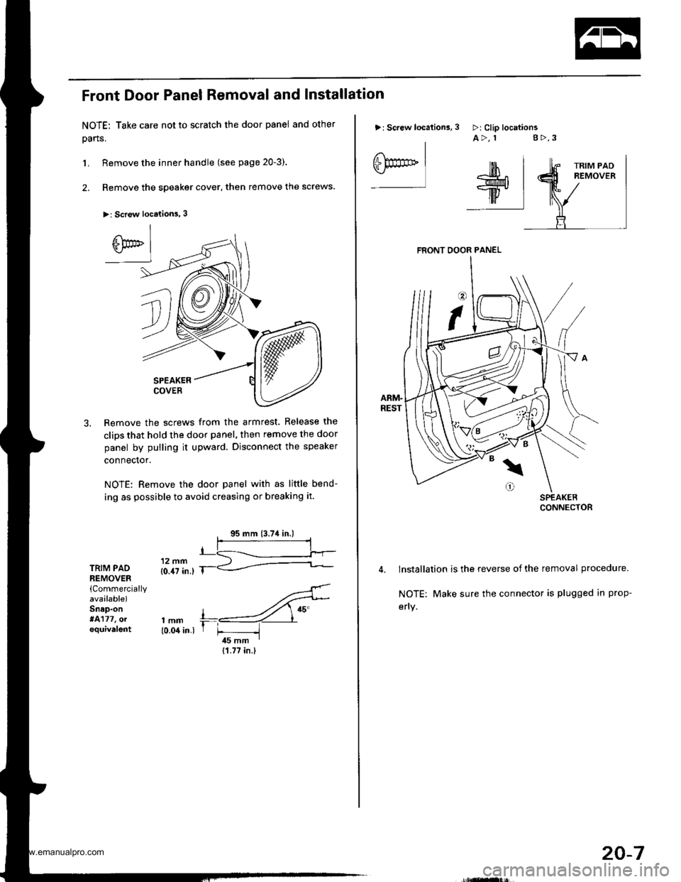
Front Door Panel Removal and Installation
NOTE: Take care not to scratch the door panel and other
pans.
L Remove the inner handle (see page 20-3).
2. Remove the speaker cover, then remove the screws.
>: Scr€w locations, 3
SPEAKERCOVER
Remove the screws from the armrest. Release the
clips that hold the door panel, then remove the door
panel by pulling it upward. Disconnect the speaker
connector.
NOTE: Remove the door panel with as little bend-
ing as possible to avoid creasing or breaking it.
TRIM PADREMOVER(Commercially
avaalable)Snap-on*4177, olequivalent
'..4'
,mm +,----ZY"{0.04 in.) r F -i45 mm I
{1.77 in.}
>: Screw location3,
I
eF** Iffil$;^r*l-w.
ttv IilF:I
3 >:Clip locttionsA>, 1 g>,3
FRONT OOOR PANEL
lnstallation is the reverse of the removal procedure.
NOTE: Make sure the connector is plugged in prop-
efly.
20-7
www.emanualpro.com
Page 989 of 1395
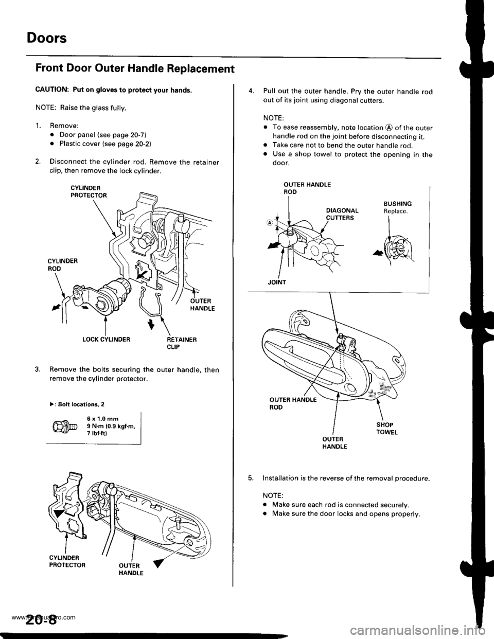
Doors
Front Door Outer Handle Replacement
CAUTION: Put on gloves to protect your hands.
NOTE; Raise the glass fully.
2.
1.Removel
. Door panel (see page 20-7). Plastic cover {see page 2O-2)
Disconnect the cylinder rod. Remove the retainer
clip, then remove the lock cylinder.
5.
6 x'1.0 mmI N.m {0.9 kgt.m,7 rbf.ftl
LOCK CYLINDER
Remove the bolts securing the
remove the cylinder protector.
>: Eolt locations,2
RETAINEBCLIP
outer handle, then
HANDLE
20-8
4. Pull out the outer handle, Pry the outer handle rod
out of its joint using diagonal cutters.
NOTE:
. To ease reassembly, note location @ ofthe outerhandle rod on the joint before disconnecting it.. Take care not to bend the outer handle rod.. Use a shop towel to protect the opening in the
door.
OUTEBHANDLE
5. Installation is the reverse of the removal procedure.
NOTE:
. Make sure each rod is connected securely.. Make sure the door locks and opens properly.
www.emanualpro.com
Page 990 of 1395
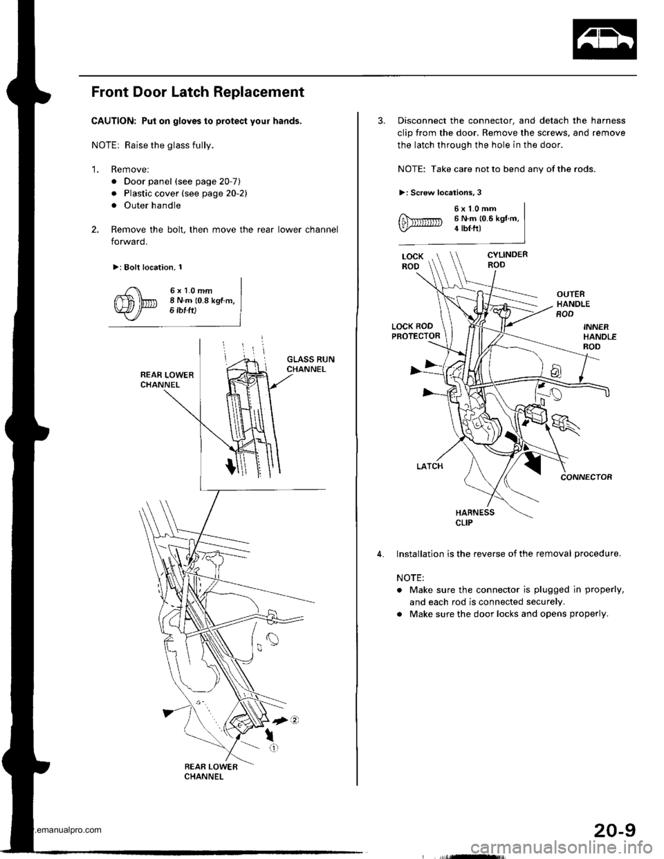
Front Door Latch Replacement
CAUTION: Put on gloves to protect your hands,
NOTEr Raise the glass fully.
'1. Remove:
. Door panel (see page 20-7)
. Plastic cover (see page 20-21
. Outer handle
2. Remove the bolt, then move the rear lower channel
forward.
>: Bolt location, 1
6xl.0mm8 N.m (0.8 kgf m,6 tbf ft)
3. Disconnect the connector, and detach the harness
clip from the door. Remove the screws, and remove
the latch through the hole in the door.
NOTE: Take care not to bend any of the rods.
>: Screw locations,3
6x1.0mm6 N.m 10.6 kgt m,4 tbf.ft)
CYLINDERROD
OUTERHANDLEROD
LOCK RODPROTECTOR
CONNECTOR
HARNESS
Installation is the reverse of the removal procedure.
NOTE:
. Make sure the connector is plugged in properly,
and each rod is connected securely.
a Make sure the door locks and opens properly.
CLIP
20-9
www.emanualpro.com
Page 992 of 1395
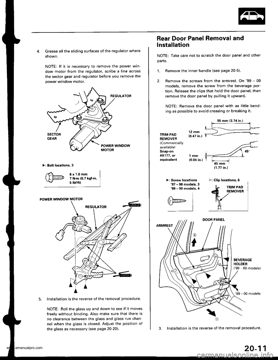
4. Grease all the sliding surfaces of the regulator where
shown.
NOTE: lf it is necessary to remove the power wrn-
dow motor from the regulator, scribe a line across
the sector gear and regulator before you remove the
power window motor.
R€GULATOF
>: Boh locations,3
6x1.0mm7 N.m lo.t kgf.m,5 tbf.ftl
POWER WINOOW MOTOR
REGULATOR
Installation is the reverse of the removal procedure.
NOTEi Rollthe glass up and down to see if it moves
freely without binding. Also make sure that there is
no clearance betlveen the glass and glass run chan
nel when the glass is closed. Adjust the position of
the glass as necessary (see page 20-20).
4
A
m^i
A
Rear Door Panel Removal and
lnstallation
NOTE: Take care not to scratch the door panel and other
parts.
1. Remove the inner handle (see page 20-5).
2. Remove the screws from the armrest. On '99 - 00
models, remove the screw from the beverage por-
tion. Release the clips that hold the door panel, then
remove the door panel by pulling it upward.
NOTE: Remove the door panel with as little bend-
ing as possible to avoid creasing or breaking it.
TBIM PADREMOVER(Commercially
available)Snap-on#4177, orequivalentlmm{0.04 in.)
>: Screw locelions'97 - 98 models. 3'99 - 00 modols, 4
11.77 in.)
DOOB PANEL
ARMREST
o
i
'99 - 00 models:
3. Installation is the reverse of the removal procedure.
\(,1
t_
T r-----/t5 mm I
EEVERAGEHOLDEN('99 00 modelsi
>i Clip locations,6
20-11
www.emanualpro.com