end HONDA CR-V 1998 RD1-RD3 / 1.G Workshop Manual
[x] Cancel search | Manufacturer: HONDA, Model Year: 1998, Model line: CR-V, Model: HONDA CR-V 1998 RD1-RD3 / 1.GPages: 1395, PDF Size: 35.62 MB
Page 909 of 1395
12.
13.
14.
Clean any dirt or grease off the ball joint.
Remove the cotter pin from the steering arm, and
remove the nut.
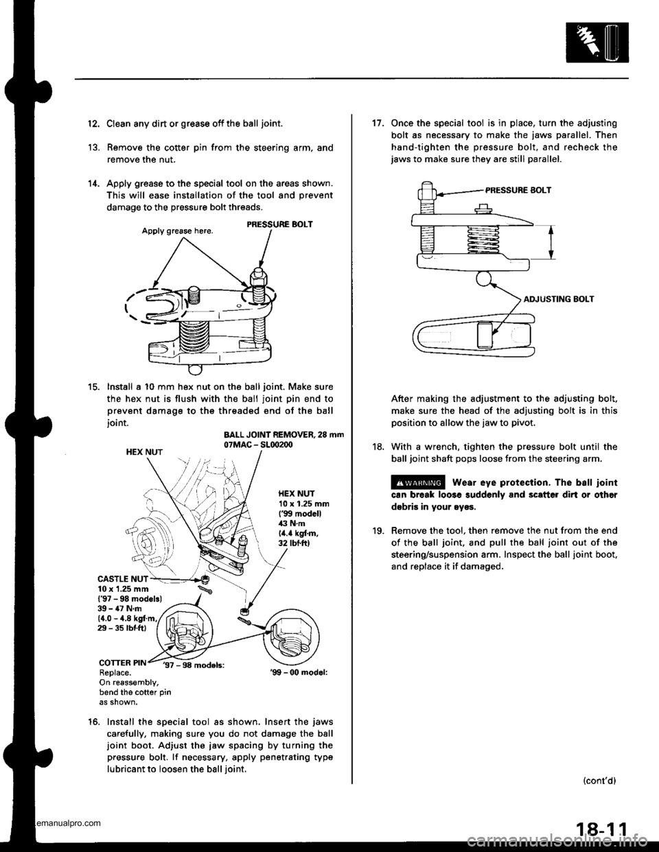
Apply grease to the special tool on the areas shown.
This will ease installation of the tool and prevent
damage to the pressure bolt threads.
PRESSURE BOLT
lnstall a 10 mm hex nut on the ball joint. Make sure
the hex nut is flush with the ball joint pin end to
prevent damage to the threaded end of the ball
joint.
BALL JOINT REMOVER, 28 mm07MAC - SL(x)2(x)HEX NUT
HEX NUT10 x 1.25 mm('99 modcll43 N.mlit.a kgl.m.32 tbtft)
37 -98 models:
tc.
6:)
CASTLE NUT10 x '1.25 mm
l'97 - 98 modcls)39 - 47 N.m{4.0 - 4.829 - 3s rbtftt
COTTERReplace.On re6ss€mbly,bend the cofter pin
16. Install the special tool as shown. Insert the jaws
carefully, making sure you do not damage the balljoint boot. Adiust the jaw spacing by turning the
pressure bolt. lf necessary, apply penetrating type
lubricant to loosen the ball ioint.
'99 -00 modol:
18.
17. Once the special tool is in place, turn the adjusting
bolt as necessary to make the jaws parallel. Then
hand-tighten the pressure bolt, and recheck thejaws to make sure they are still parallel.
ADJUSTING BOLT
After making the adjustment to the adjusting bolt,
make sure the head of the adjusting bolt is in this
position to allow the jaw to pivot.
With a wrench, tighten the pressure bolt until the
ball joint shaft pops loose from the steering arm.
@ wear eye protection. The balt iointcan break loose suddenly and scatter dirt or other
dsbris in your ey€s.
Remove the tool, then remove the nut from the end
of the ball joint, and pull the ball joint out of the
steering/suspension arm. Inspect the ball joint boot.
and replace it if damaged.
(cont'dl
1(|
18-1 1
www.emanualpro.com
Page 910 of 1395
Front Suspension
Knuckle/Hub Replacement (cont'd)
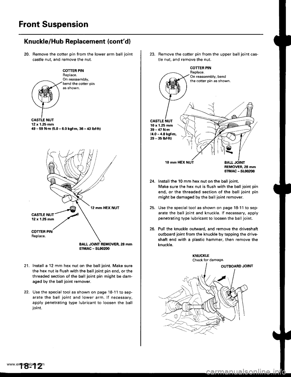
20. Remove the cotter pin from the lower arm ball joint
castle nut, and remove the nut.
COTTER PINReplace.On ra6ssembly,bend the cofter pin
CASTI.E NUT12 x 1.25 mmilg - 59 N.m (5.0 - 6.0 kgf.m, 36 - a3 lbf.ftl
CASTLE NUT12 x 1.25 mm
COITER PINReplace.
BALL JOINT REMOVER, 28 mm07MAC - Sl(xr2(x,
Install a 12 mm hex nut on the ball joint. Make sure
the hex nut is flush with the ball joint pin end, or the
threaded section of the ball joint pin might be dam-
aged by the ball joint remover.
Use the special tool as shown on page 18-11 to sep-
arate the ball joint and lower arm. lf necessary,
apply penetrating type lubricant to loosen the balljoint.
18-12
23. Remove the cotter pin from the upper ball joint cas-
tle nut, and remove the nut.
COTTER PINReplace.On reassembly, bendthe cotter pin as shown.
CASTLE NUT10 x 1.25 mm39 - 47 N.m14.0 - ,4.8 kgt m,29 - 35 tbt.ftl
24.
25.
26.
10 mmnEMOVER, 28 mm07MAC _ SLtD2(xl
Install the 10 mm hex nut on the ball joint.
Make sure the hex nut is flush with the ball joint pin
end, or the threaded section of the ball joint pin
might be damaged by the ball joint remover.
Use the special tool as shown on page 18-11 to sep-
arate the ball joint and knuckle. lf necessary, apply
penetrating type lubricant to loosen the ball joint.
Pull the knuckle outward, and remove the driveshaft
outboard joint from the knuckle by tapping the driv+
shaft end with a pl8stic hammer, then remove the
knuckle.
KNUCKI.ECheck lor damage.
www.emanualpro.com
Page 911 of 1395
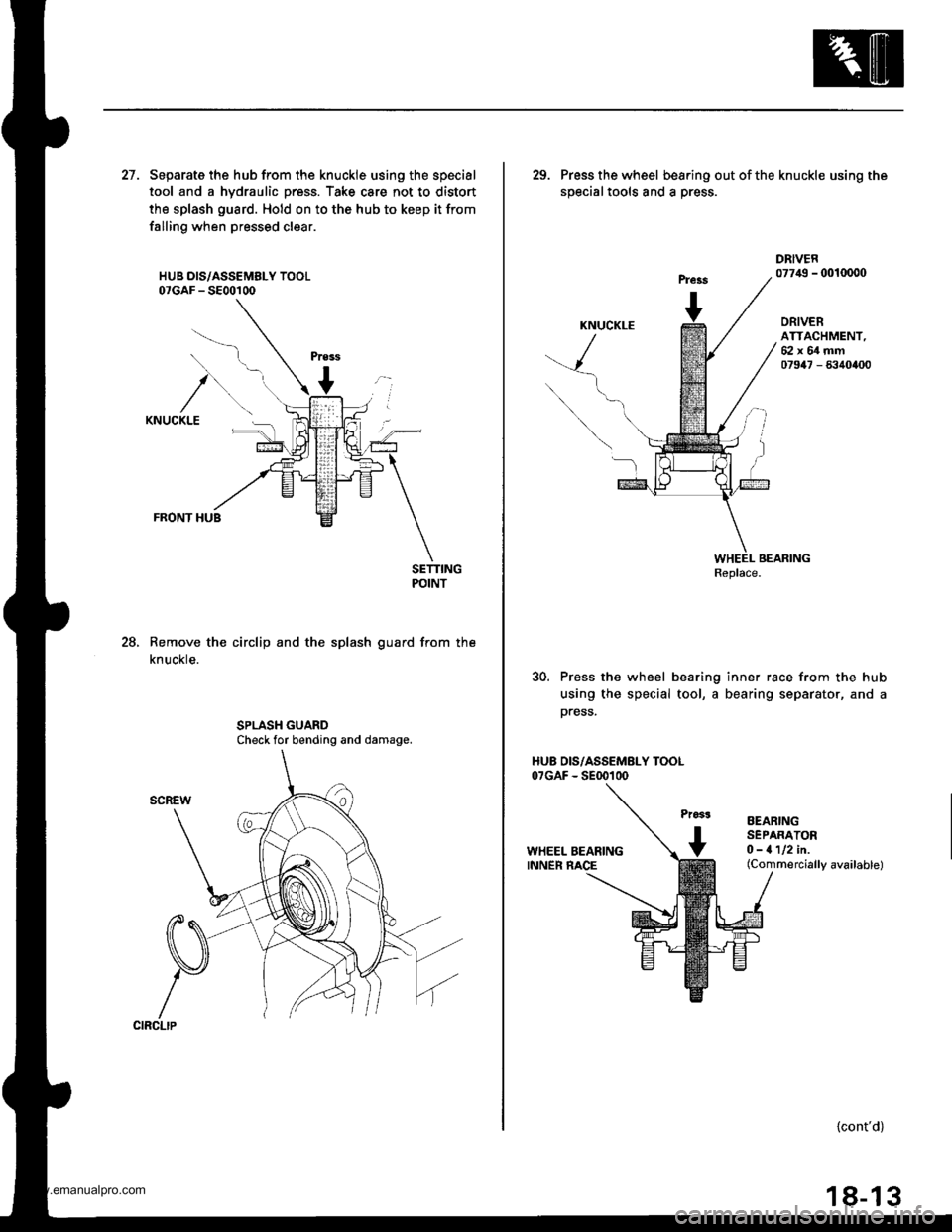
27. Separate the hub from the knuckle using the special
tool and a hydraulic press. Take care not to distort
the splash guard. Hold on to the hub to keep it from
falling when pressed clear.
HUB DIS/ASSEMELY TOOL07GAF - 5800100
FRONT HUB
SETTINGPOINT
Remove the circlip and the splash guard from the
knuckle.
28.
Check for bending and damage.
29. Press the wheel bea.ing outofthe knuckle using the
soecialtools and a Dress.
DRIVER077,19 - 0010000
ORIVERATTACHMENT,62x64mm07947 - 6340400
30. Press the wheel bearing inner race from the hub
using the special tool, a bearing separator, and a
press.
HU8 OIS/ASSEMBLY TOOL07GAF - SE00100
EEARINGSEPARATORO-1112in.(Commercially available)
{cont'd}
18-13
www.emanualpro.com
Page 914 of 1395
Front SuspensionFront Damper
Ball Joint Boot Replacement
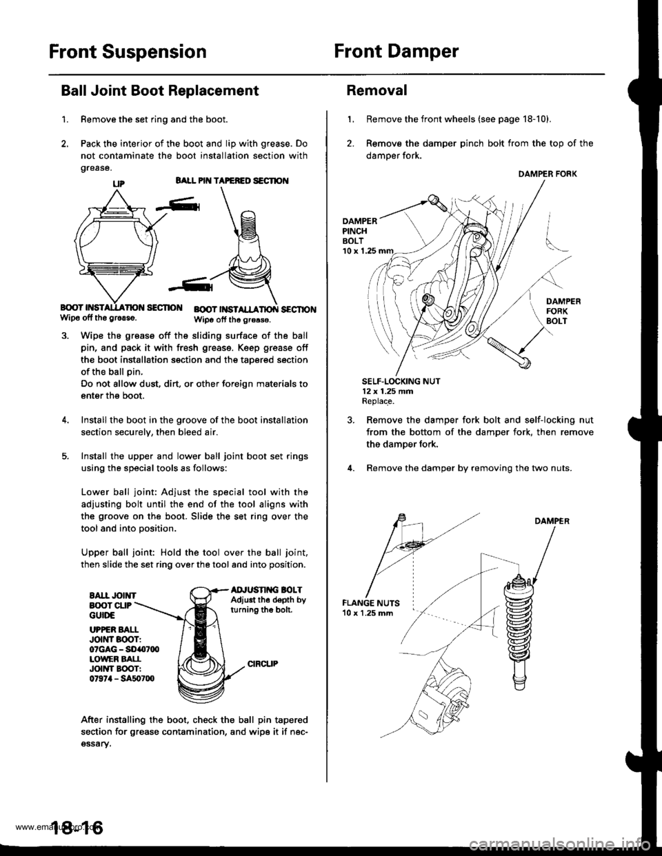
1.
BALL PIT{ TAPEFEO S€CTION
B{rcY HSISECTIO BOOT |NSTSECTIONwip6 off tho gr6aso.Wipo otf th6 grors€.
Wipe the grease off the sliding surface of the ball
pin, and pack it with fresh greass. Keep grease off
the boot installation section and the taoered section
of the ball pin.
Do not allow dust, dirt, or other foreign materials to
enter the boot.
Install the boot in the groove of the boot installation
section securelv, then bleed air.
Install the upper and lower ball joint boot set rings
using the special tools as follows:
Lower ball joint: Adjust the special tool with the
adjusting bolt until the end of the tool aligns with
the groove on the boot. Slide the set ring over the
tool and into oosition.
Upper ball joint: Hold the tool over the ball joint,
then slide the set ring over the tool and into position.
EAII JOINTAD'USN G BOLTAdjust th6 depth byturning the bolt.
Remove the set ring and the boot.
Pack the interior of the boot and lip with grease. Do
not contaminate the boot installation section with
grease.
B(X)T CUPGUttrE
UPPER BAI.IJott'tr Boor:07GAG - SO407q)LOWEF BATIJOIIYI EOOTI0t97il - SA507lXl
After installing the boot, check the ball pin tapered
section for grease contamination, and wipe it if nec-gssary.
18-16
Removal
1, Remove the front wheels (see page 18-10).
2. Remove the damper pinch bolt from the top of the
damper fork.
DAMPERPINCHBOLT'10 x 1.25
SELF.LOCKING NUT12x 1.25 fifiReplace.
Remove the damper fork bolt and self-locking nut
from the bottom of the damper fork, then remove
the damper fork.
Remove the damper by removing the two nuts.
DAMPER
DAMPER FORK
www.emanualpro.com
Page 915 of 1395
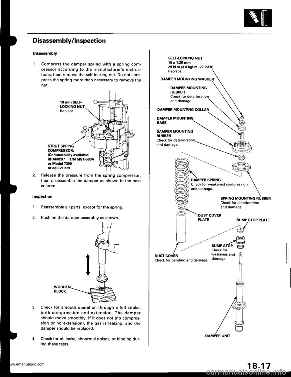
Disassembly/ Inspection
Disass.mbly
1. Compress the damper spring with a spring com-
pressor according to the manufacturer's instruc-
tions, then remove the self-locking nut. Do not com-press the spring more than necessary to remove the
nur.
10 mm SELF-LOCKINGReplace.
STRUTCOMPRESSOR:lComm6rcially availablo)BRANICK@ T/N MST-580Aor Mod6l 7200or equivalent
Release the pressure from the spring compressor,
then disassemble the damper as shown in the next
cotumn.
Inspection
1.Reassemble all parts, except for the spring.
Push on the damper assembly as shown.
Check for smooth operation through a full stroke,
both compression and extension. The damper
should move smoothly. lf it does not (no compres-
sion or no extension), the gas is leaking, and the
damper should be replaced.
Check for oil leaks, abnormal noises, or binding dur-
ing these tests.
2.
29 N.m (3.0 kgl.m,22lbtftlReplace.
DAMPER MOUNTING WASHER
DAMPER MOUNTING
SELF-LOCKING NUT10 x 1.25 mm
RUBBERCheck forano oamage.
DAMPER MOUAMNG COLLAR
DAMPER MOUNTINGBASE
DAMPER MOUNTINGRUBBERCheck for det€riorationano oamage.
BUMP STOP PLATE
DUSTCheckfor bending and damage.
..rgBUMPSTOP g
weakness anddamage,
SPRING MOUNTING
www.emanualpro.com
Page 917 of 1395

Rear Suspension
Suspension Arms Replacement
@ when the suspension arms are to be removed, plsce additional weight in lhe trunk beto.o hoisting. when
substantial weight is removed from the rear of the vehicle, the center ot grsvity m8y chango causing the vehicle to tip
forward.
Note these items during replacement:
. Replace the self-locking nuts after removal.
. Any bolts or nuts connected to rubber mounts or bushings should be tightened with the vehicle on the ground.
. Make sure the toe adjusting bolts on the compensator arm are installed in the same direction,
. After installing the suspension arm, check the rear wheel alig nment, and adjust if necessa ry (see page 18-4),
STABILIZER BARCheck for bendingor oamage.
FLANGE EOLT10 x 1.25 mm64 N.m 16.5 kgf.m,47 lbf.ft)
FLANGE BOLT10 x 1.25 mm54 N.m (5.5 kgt.m, / t40 lbf.ftt. --1 \ \A1(\
\a'v..:r
UPPER ARM BUSHINGCheck for deteriorationand damage.
il ,
FLANGE BOLT'l0 r 1.25 mm54 N.m (5.5 kgf.m,
8 mm EOLTS22 N.m {2.2 kgf.m, 16 bl.ftl
40 rbtft)
'ano oamage.
TRAILING ARMCheck for bending
stLtcoNE
-6lUPPER ARM
COMPENSATORARM BUSHING
64 N.m 16.5 kgf.m, 47 lbtftl
SELF.LOCKING NUT
BUSHING
FLANGE BOLT10 x 1.25 mm54 N.m {5.5 kgf.m, 40 lbf.ft}
FLANGE BOLTS10 x 1.25 mm39 N.m 14.0 kgf.m, 29 lbf.ft)stLtcoNE
.@iCOMPENSATORARM BUSHING
UPPER ARMCheck lor bending or damage.
FLANGE NUT10 x 1 .25 mm29 N.m {3.0 kg{.fl,22 lbf.ft}Before tightening the flange nut,position the balljoint pinin the middle of its range oftravel, with the suspension undervehicle load.
10 x 1.25 mm 29 N.m (3.0 kgl.m, 22 tbf.ft)Replace.Hold the ball ioint pin using a hex wrenct,,and tighten the self-locking nut.
STABILIZER LINK
Check tor damage.
LOWER ARM BUSHINGCheck for deterioration and damage.
. Check for bending and damage.. Check the bushing tor deterioration anddamage.
LOWEN ARM
-6ilstLrcoNE
STABILIZER 8AR
,/ FLANGE BOLT
// 10 x 1.25 mm
^/ s4 N.m 15.5 kst'm, 40 lbf ftl
BUSHING
www.emanualpro.com
Page 922 of 1395
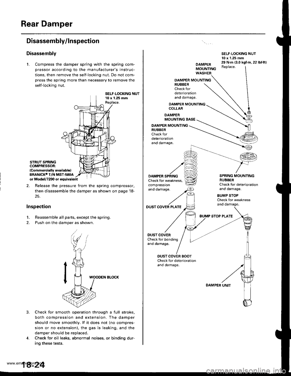
Rear Damper
Disassembly/lnspection
Disassembly
L Compress the damper spring with the spring com-
pressor according to the manufacturer's instruc-
tions, then remove the self-locking nut. Do not com-
press the spring more than necessary to remove the
self-locking nut.
SELF-LOCKING NUT10 x 1.25 mmReplace.
STRUT SPRINGCOMPRESSOR:lCommercirlly avaihblo)BRANICKO I/N MSI-580Aor Mod6l/7200 or equivalent
2. Release the pressure from the spring compressor,
then disassemble the damper as shown on page 18-
25.
Inspection
1. Reassemble all parts, except the spring.
2. Push on the damper as shown.
3.
WOODEN ELOCK
Check for smooth operation through a full stroke,
both compression and extension. The damper
should move smoothly. lf it does not (no compres-
sion or no extension), the gas is leaking, and the
damper should be replaced.
Check for oil leaks, abnormal noises, or binding dur-
ino these tests.
4.
SELF-LOCKING NUT10 x 1.25 mm
OAMPERMOUNTINGWASHER
29 N.m {3.0 kgf.m, 22 lbf.ft)Beplace.
OAMPER MOUNTINGRUBBERCheck fordeteriorationano oamage.
DAMPER MOUNTINGCOLLAR
DAMPERMOUNTING BASE
DAMPER MOUNTINGRUBBERCheck fordeteriorationano oamage.
'"dd"^.s"'
//F,
DAMPERCheck for weakness,compressron
DUST COVER PLATE
DUST COVERCheck for bendingand damage.
SPRING MOUNTINGRUBBERCheck Ior deteriorationand damage.
BUMP STOPCheck for weaknessano oamage.
DUST COVEN BOOTCheck for deterioralionano oamage.
BUMP STOP PLATE
DAMPER
www.emanualpro.com
Page 929 of 1395
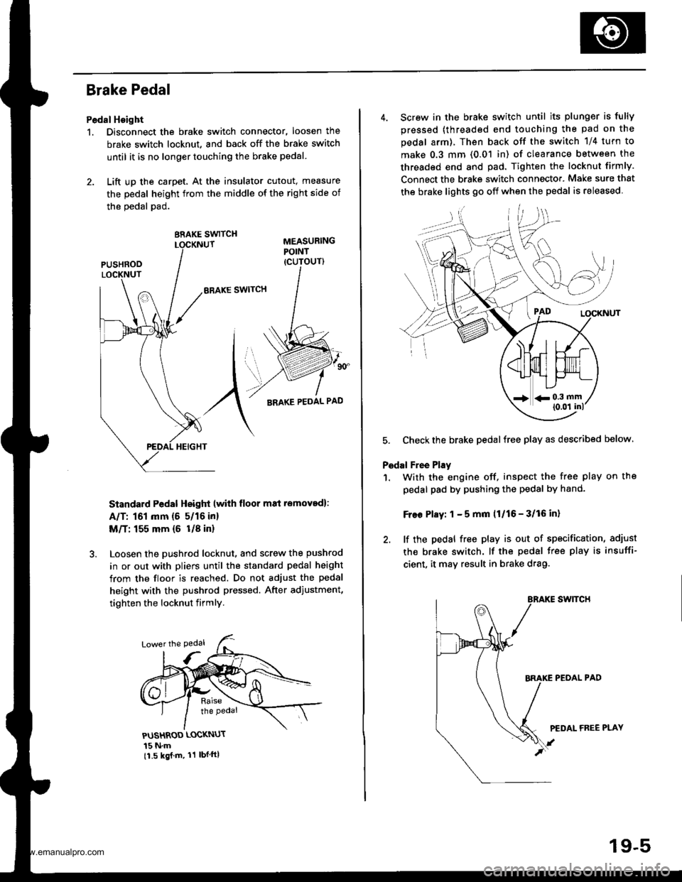
Brake Pedal
Pedal Hoight
1. Disconnect the brake switch connector, loosen the
brake switch locknut, and back off the brake switch
until it is no longer touching the brake pedal.
2. Lift up the carpet, At the insulator cutout, measure
the pedal height from the middle of the right side of
the oedal pad.
BRAKE SWITCH
ERAKE SWITCH
Standard Pedal Height (with floor m8i removed):
A/T: 161 mm (5 5/16 in)
M/T: 155 mm {6 U8 in}
Loosen the pushrod locknut, and screw the pushrod
in or out with pliers until the standard pedal height
from the floor is reached. Do not adjust the pedal
height with the pushrod pressed. After adiustment,
tighten the locknut firmly.
PUSHROD LOCKNUT
15 N.m11.5 kgj m, 11 lbf ftl
4. Screw in the brake switch until its plunger is fully
pressed (threaded end touching the pad on the
pedal arm), Then back otf the switch 1/4 turn to
make 0.3 mm (0.01 in) of clearance between the
threaded end and pad. Tighten the locknut firmly.
Connect the brake switch connecto.. Make sure that
the brake lights 90 off when the pedal is released
5. Checkthe brake pedalfree play as described below
Pedal Free Play
1. With the engine off. inspect the free play on the
pedal pad by pushing the pedal by hand-
Free Play: 1 - 5 mm (1/16 - 3/16 in)
2. lf the pedal free play is out of specification, adiust
the brake switch. lf the pedal free play is insuffi-
cient, it may result in brake drag.
swtTcH
PEOAL PAD
PEDAL FREE PLAY
19-5
www.emanualpro.com
Page 936 of 1395
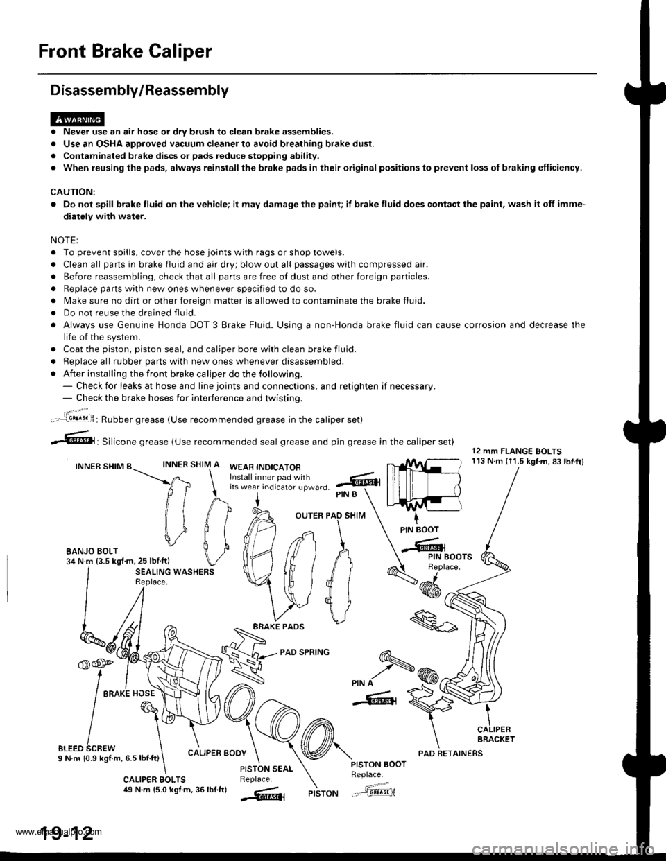
Front Brake Caliper
Disassembly/Reassembly
. Never use an air hose or dry brush to clean brake assemblies.
. Use an OSHA approved vacuum cleaner to avoid breathing brake dust.
. Contaminated brake discs or pads reduce stopping ability.
. When reusing the pads, always reinstallthe brake pads in their original positions to prevent loss ol braking efficiency.
CAUTION:
. Do not spill brake fluid on the vehicle; it may damage the paint; if brake fluid does contact the paint, wash it off imme-
diatelY with water.
NOTEI
. To prevent spills, cover the hose joints with rags or shop towels.
. Clean all pans in brake fluid and air dry; blow out all passages with compressed air.
. Before reassembling, check that all parts are free of dust and other foreign particles.
. Replace parts with new ones whenever specified to do so.
. Make sure no dirt or other foreign matter is allowed to contaminate the brake fluid.
. Do not reuse the drained fluid.
. Always use Genuine Honda DOT 3 Brake Fluid. Using a non-Honda brake fluid can cause corrosion and decrease the
life of the system.
. Coat the piston, piston seal, and caliper bore with clean brake fluid.
. ReDlace all rubber oarts with new ones whenever disassembled.
. After installing the front brake caliper do the following.- Check for leaks at hose and line joints and connections, and retighten if necessary.- Check the brake hoses for interference and twistinq.
SHIM
12 mm FLANGE BOLTS113 N.m (11.5 kgtm,83lbf.ftlINNER
ft
il1
#
\i
#
PIN B
OUTER PAO SHIM
PAD SPRING
IPIN BOOT
-Cr
SEALING WASHERSReplace.4dd*
ERAKE PADS
'f,-rre
/ tto*l "o"\
t@I
/\'
sLreo 6cnew \I N m 10.9 kStm, 6.5 lbnft)
\
6-
>PIN A
-6, {
CALIPER BOOY
CALIPER EOLTS49 N.m {5.0 kgl.m, 36lbf.ftl
PISTON AOOTReplace.
"..-a=a-...,--"sEqriPISTON
t".:jil,,.'.1!!!!9!il: Rubber grease (Use recommended grease in the caliper set)
irf"i:;;T::fl,-J'I",0 .@
--6, Silicone grease (use recommended seal grease and p,n grease in the caliper set)
INNER SHIM BWEAB INDICATOR
EANJO BOLT34 N.m {3.5 kgf m,25 lblftl
PISTON SEALReplace.
AFACKET
19-12
PAD RETAINERS
www.emanualpro.com
Page 937 of 1395
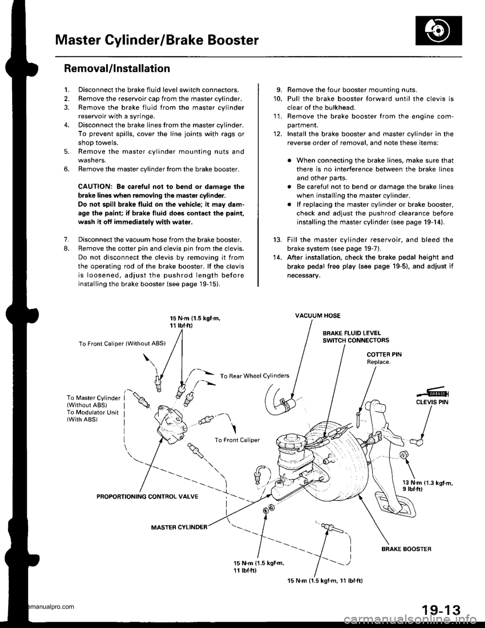
Master Cylinder/Brake Booster
Removal/lnstallation
1, Disconnect the brake fluid level switch connectors.
2. Remove the reservoir cap from the master cylinder.
3. Remove the brake fluid from the master cvlinder
reservoir with a syringe.
4. Disconnect the brake lines from the master cylinder.
To prevent spills, cover the line joints with rags or
shop towels.
5. Remove the master cylinder mounting nuts and
wasners.
6. Remove the master cylinder from the brake booster.
CAUTION: Be careful not to bend or damage the
brake lines when removing the master cylinder.
Do not spill brake fluid on the vehicle; it may dam.
age the paint; it brake fluid does cont.ct the paint,
wash it oft immediately with water.
7. Disconnect the vacuum hose from the brake booster.
8. Remove the cotter pin and clevis pin from the clevis.
Do not disconnect the clevis by removing it from
the operating rod of the brake booster. lf the clevis
is loosened, adjust the pushrod length before
installing the brake booster (see page 19-15).
To Front Caliper (Without ABS)
\\
15 N.m {1.5 kgtm, vAcuuM HosE
r r rbf.ft) |
/ | BRAKE FLUTD LEvEL
/l /
swrrcHcoNNEcroRs
/ I I I COTTER PIN
I I / neotace
l,/-- ro Rear wheet cylinders / | I
h ./-''' /. I I IYli //*s (.S
I /r:
9. Remove the four booster mounting nuts.'10. Pull the brake booster forward until the clevis is
clear of the bulkhead.
11. Remove the brake booster from the enqine com-
panment.
12. Install the brake booster and master cylinder in the
reverse order of removal, and note these items:
. When connecting the brake lines, make sure that
there is no interference between the brake lines
and other parts.
. Be careful not to bend or damage the brake lines
when installing the master cylinder.
. lf replacing the master cylinder or brake booster,
check and adjust the pushrod clearance before
installing the master cylinder (see page 19-14).
Fill the master cylinder reservoir, and bleed the
brake system (see page 19-7).
After installation, check the brake pedal height and
brake pedal free play (see page 19-5), and adjust if
necessary.
13 N.m 11.3 kg{.m,I rbf.ft)
13.
14.
To Master Cylinder(Without ABS)To Modulator Unit(with ABs)@-\
\
^ To Front Caliper
9i\.
-#qCLEVIS PIN
):-,/
PROPORTIONING CONTROL VALVE
MASTER CYLINDER
15 N.m (1.5 kgf.m, 11 lbl.ftl
BRAXE BOOSTER
www.emanualpro.com