end HONDA CR-V 1998 RD1-RD3 / 1.G Workshop Manual
[x] Cancel search | Manufacturer: HONDA, Model Year: 1998, Model line: CR-V, Model: HONDA CR-V 1998 RD1-RD3 / 1.GPages: 1395, PDF Size: 35.62 MB
Page 1019 of 1395
Glass
Ouarter Glass Replacement (cont'd)
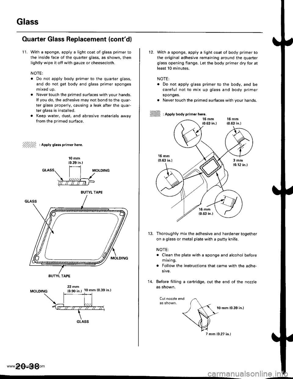
1 1. With a sponge, apply a light coat of glass primer to
the inside face of the quaner glass, as shown, then
lightly wipe it off with gauze or cheesecloth.
NOTE:
. Do not apply body primer to the quarter glass,
and do not get body and glass primer sponges
mrxed up.
. Never touch the primed surfaces with your hands.
It you do, the adhesive may not bond to the quar-
ter glass properly. causing a leak after the quar
ter glass is installed.
. Keep water, dust, and abrasive materials away
from the primed surface.
7///f ' aeery sra$ primer here.
10 mm{0.39 in.)
BUTYL TAPE
BUTYL TAPE
MOLOING23 mm10.90 in.)10 mm 10.39 in.)
GLASS
20-38
With a sponge, apply a light coat of body primer to
the original adhesive remaining around the quaner
glass opening flange. Let the body primer dry for at
least 10 minutes.
NOTE:
. Do not apply glass primer to the body, and be
careful not to mix up glass and body primer
sponges.
. Never touch the primed surfaces with your hands.
'/fu, : Apply body primer here.
'13.Thoroughly mix the adhesive and hardener together
on a glass or metal plate with a putty knife.
NOTE:
. Clean the plate with a sponge and alcohol before
m ixing.
. Follow the instructions that came with the adhe-
slve.
Before filling a cartridge, cut the end of the nozzle
as snown.
Cut nozzle end
10 mm {0.39 in.)
7 mm {0.27 in.)
14.
www.emanualpro.com
Page 1022 of 1395
Removal and Installation
CAUTION:
. Put on gloves to protect your hands,
. When prying with a tlat-tip screwdrivel, wrap it with protective tape to prevent damage.
. When removing the support strut of the rear hatch glass, you will need to open or close the rear hatch glass by hand.
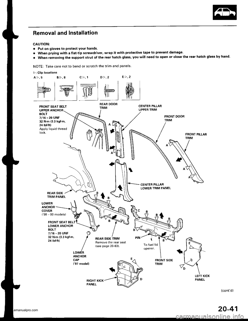
NOTE: Take care not to bend or scratch the trim and panels.
>: Clio locations
a>,5c>, 1o>.2e>,2B >,8
UPPERBOLT7/16 - 20 UNF32 N.m {3.3 kgf.m,24 rbt.ft)Apply liquid thread
CENTER PILLARLOWER TRIM PANEL
LOWERANCHOBCOVER('98 00 models)
{cont'd)
I l_lss-l , | 'rrl
elElw"lel sl
FRONT SEAT BELT
FRONT SEAT BELLOWER ANCHORBOLT7/15 - 20 UNF32Nm(3.3kgf.m,24 tbt.ftl
ANCHORCAP('97 model)
REAR DOORTRIM
REAR SIDE TRIMtlemove the rear seat(see page 20 63).
REAR SIDE
20-41
www.emanualpro.com
Page 1025 of 1395
lnterior Trim
Headliner Removal and Installation
CAUTION: When prying with a tlat-tip screwdriver,
wrap it with protective tape to prevent damage.
NOTE:
. Take care not to bend and scratch the headliner.o Be careful not to damage the dashboard and other
interior trim.
1. Remove:
. Front and rear door side trim (see page 20-41). Front pillartrim (see page 20-41)
. Center pillar lower trim panel (see page 20-41). Center pillar upper trim (see page 20 41). Rear seat (one side, see page 20-63). Cargo area floor and cargo storage bin
{see page 20-43)
. Rear trim panel (see page 20-421
. Rear side trim panel (oneside, see page 20-42l,
. Rear hatch glass support strut (one side, seepage 20-78)
. Ouaner pillar trim panel {one side, see page 20-
42)
. Ceiling light, interior light and trunk light(see section 23)
. Rearview mirror (see page 20-28)
2. Remove the sunvisor and holder from each side.
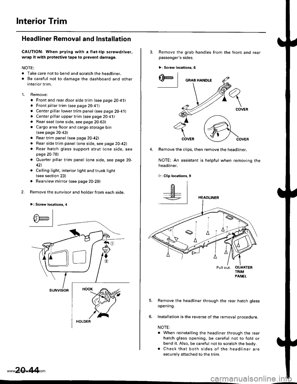
>: Scaew location3, 4
I
A\"r- |Yr* || -
suNvtsoR
20-44
3. Remove the grab handles from
passenger's sides.
>r Screw locations, 6
the front and rear
ry_l
COVER
4. Remove the clips, then remove the headliner.
NOTE: An assistant is helpful when removing the
headliner.
>: Clip locations,9
HEADLINER
Pullout. OUARTERTRIMPANEL
5. Remove the headliner through the rear hatch glass
openrng.
6. Installation is the reverse of the removal procedure.
NOTE:
. When reinstalling the headliner through the rear
hatch glass opening, be careful not to fold or
bend it, Also, be careful not to scratch the body.. Check that both sides of the headliner are
securely attached to the trim.
www.emanualpro.com
Page 1038 of 1395
Front Seat Removal and Installation
CAUTION: When prying whh a tlat-tip screwdrivor, wrap
it with proteqtive tape to prevent damage.
NOTE: Take care not to scratch the bodv or tear the seat
covers.
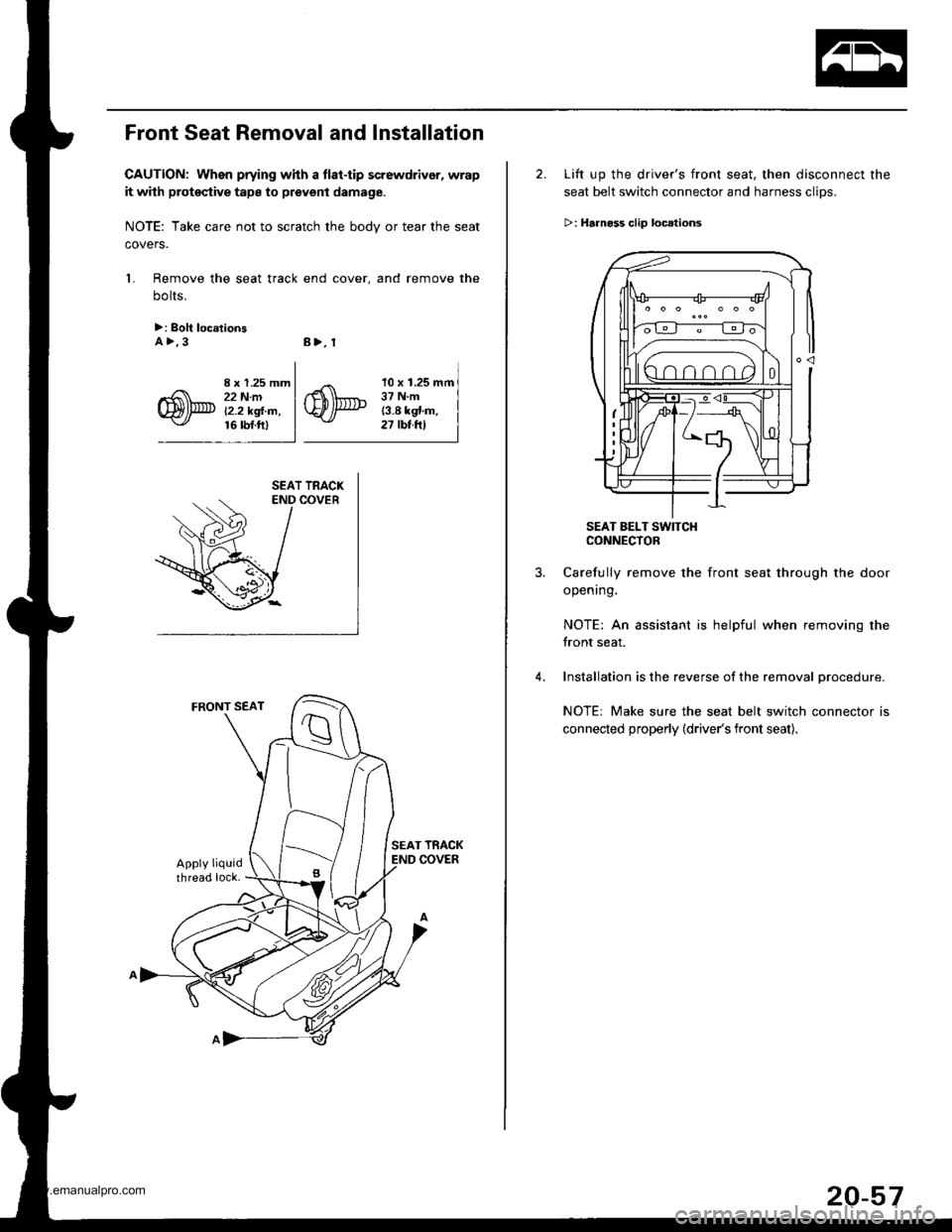
1. Remove the seat track end cover, and remove the
bolts.
>: Bolt loc.tionsA>.3B>, 1
I x 1.25 mm22 N.mi'2.2 kgl.m,16 rbf.ftl
10 x 1.25 mm37 N.m13.8 kgt.m,27 tbt.ftl
2. Lift up the driver's front seat, then disconnect the
seat belt switch connector and harness clips.
>: Hrrnoss clip loc.lions
SEAT BELT SW]TCHCONNECTOR
Carefully remove the front seat through the door
opening.
NOTE: An assistant is helpful when removing the
front seat.
Installation is the reverse of the removal procedure.
NOTE: Make sure the seat belt switch connector is
connected properly (driver's front seat).
20-57
www.emanualpro.com
Page 1053 of 1395
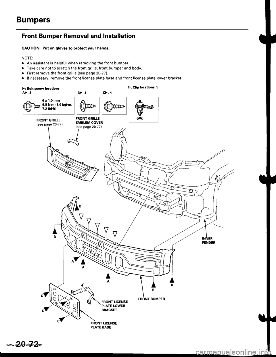
Bumpers
Front Bumper Removal and Installation
CAUTION: Put on gloves to protec,t your hands.
NOTE:
. An assistant is helpful when removing the front bumper.
. Take care not to scratch the front grille, lront bumper and body.
o First remove the front grille (see page 20-77).
. lf necessary, remove the front license plate base and front license plate lower bracket.
B>, 4 C>,4
4 .<\l
S))PF | ffi)m>lv I Y./ |
FRONT GRILLEEMBLEM COVER(see page 20-77)
>: Clip locations,5
.r., I
w€lw
FENDER
IB
FRONT BUMPER
20-72
>: Boli screw locationsA>,3
6x1.0mm9.8 N.m (1.0 kgf.m,7.2 tbt t0
FRONT GRILLE(see page 20-77)
tx -
\{_:
www.emanualpro.com
Page 1064 of 1395
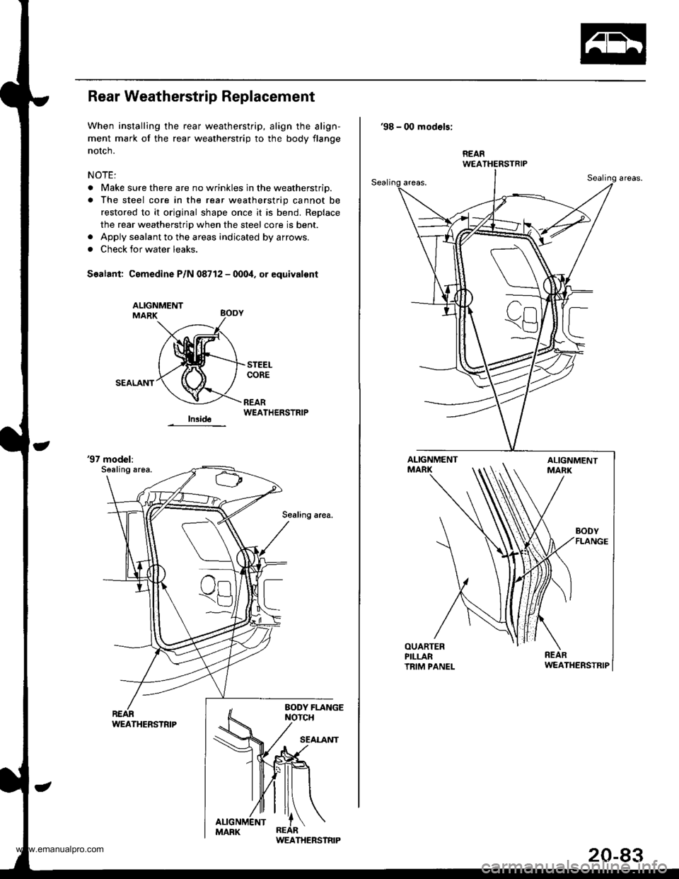
Rear Weatherstrip Replacement
When installing the rear weatherstrip, align the align-
ment mark of the rear weatherstrip to the body flange
notch.
NOTE:
. Make sure there are no wrinkles in the weatherstrio.
. The steel core in the rear weatherstrip cannot be
restored to it original shape once it is bend. Replace
the rear weatherstrip when the steel core is bent.. Apply sealant to the areas indicated by arrows.
. Check for water leaks.
Sealant: Cemedine P/N 08712 - 000i1, or equivalont
SEALANT
WEATHERSTRIP
'97 model:Sealing area.
Sealing area.
WEATHERSTRIP
'98 - 00 modols:
BODYFLANGE
REARWEATHERSTRIP
www.emanualpro.com
Page 1065 of 1395
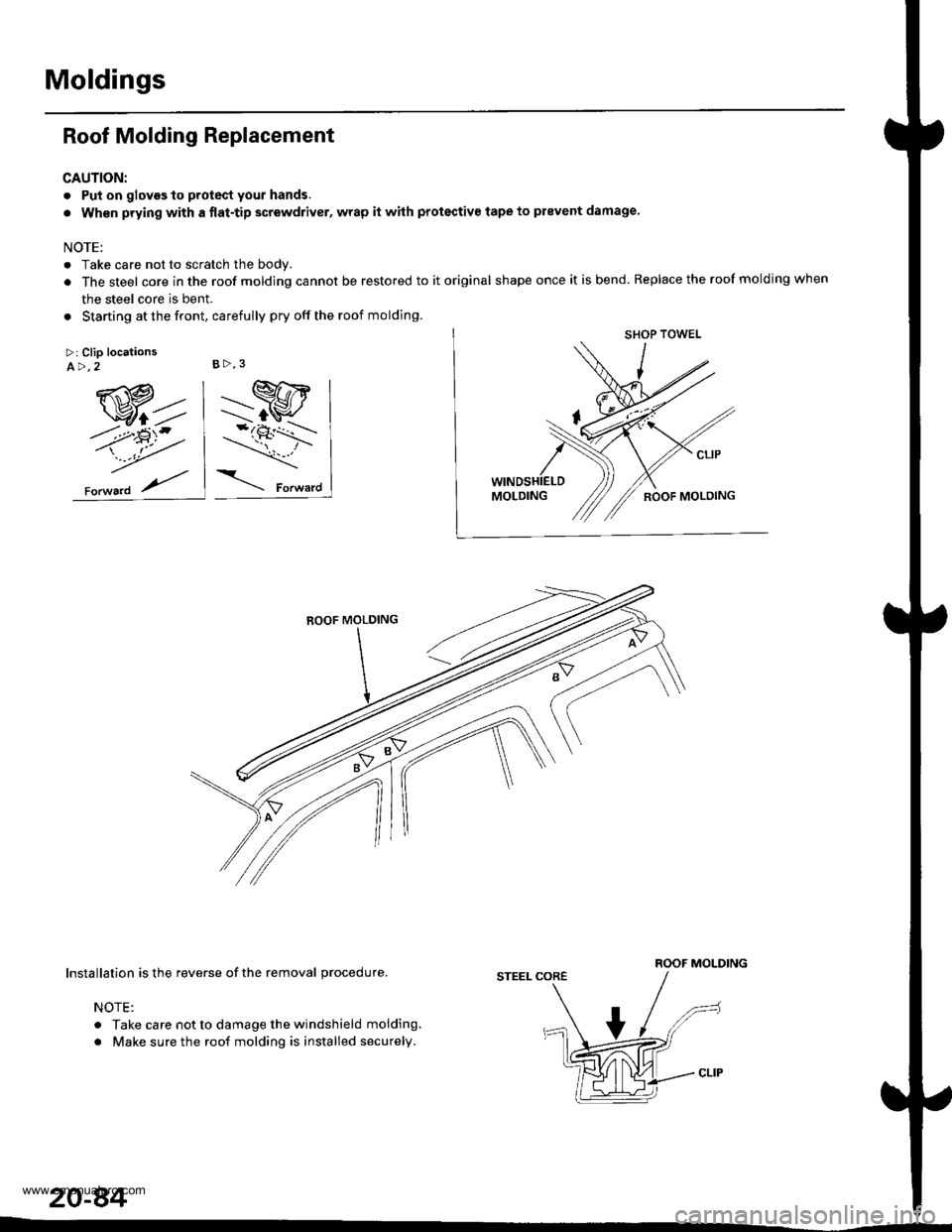
Moldings
Roof Molding Replacement
CAUTION:
. Put on glovgs to protect your hands.
. Wh€n prying with a {lat-tip screwdriver, wrap it whh protective tape to prevent damage
NOTE:
. Take care not to scratch the body.
. The steel core in the roof molding cannot be restored to it original shape once it is bend. Replace the roof molding when
the steel core is bent.
. Starting at the front, carefully pry off the roof molding.
>: Clip locationsA>,2
ROOF MOLDINGInstallation is the reverse of the removal procedure.
NOTE:
. Take care not to damage the windshield molding.
. Make sure the roof molding is installed securely.
STEEL CORE
B>,3
20-84
www.emanualpro.com
Page 1067 of 1395
Moldings
Door Moldings Replacement (cont'd)
It the old molding is to be reinstalled:
The following materials and tools are required to repair
the molding.
NOTE: Followthe manufacturer's instructions.
Materials: (Reference)
. Stripe remover
3M 08907
. Stripe adhesive remover
3M 08908
. Adhesive tape
3M Super Automotive Attachment Tape
Tools:
. Protective tape
. Knife or Cutter
. Sponge or Shop towel
. Infrared dryer
. Film
. Plastic putty knife
. Alcohol
CAUTION: Put on gloves to protect your hands,
1. lf necessary, replace any damaged clips on the mold-
ang.
2. Apply the stripe remover evenly to the bonding sur-
face of the body and molding.
3. Cover the bonding surface of the body and molding
with a film, then heat to 104 - 122"F (40 - 50'C) for 5- 10 minutes with an infrared dryer.
NOTE: Use care when heating to prevent deforma-
tion of the body and molding.
4. Carefully scrape the adhesive tape with a plastic
putty knife.
For removal of adhesive tape residue, follow-up with
stripe adhesive remover, then scrape the adhesive
tape with a plastic putty knife.
Remove the protective tape, then clean the bonding
surface with a sponge dampened in alcohol.
NOTE: Make sure the bonding surface is kept free or
water, oil and grease.
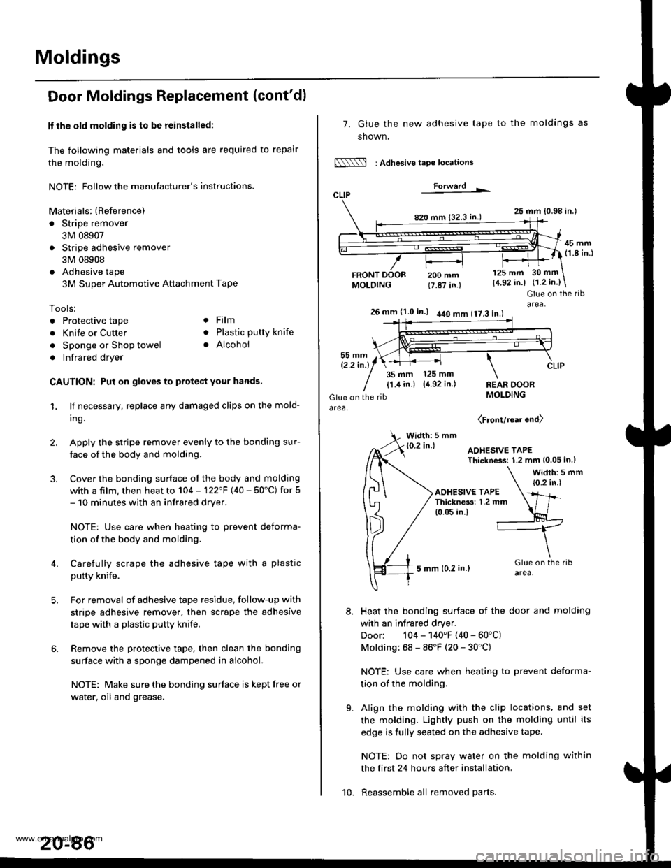
7. Glue the new adhesive tape
snown,
N : Adlesive tape locations
Forwerd L
820 mm 132.3 in.)
FRONTMOLDING
to the moldings as
25 mm {0.98 in.l
45 mm(1.8 in.l
200 mm(7.87 in.)
125 mm
{4.92 in.)30 mm
{1.2 in.}
t'.
Glue on the ribarea,26 mm (1.0 in.) 440 mm 117.3 in.l
35 mm 125 mm
{1.4 in.) {4.92 in.)REAR DOORMOLDING
(Front/rear end)
Width: 5 mm
Heat the bonding surface of the door and molding
with an infrared dryer.
Door: 104 - 140'F (40 - 60'C)
Molding: 68 - 86'F (20 - 30'C)
NOTE: Use care when heating to prevent deforma-
tion of the molding.
Align the molding with the clip locations, and set
the molding. Lightly push on the molding until its
edge is fully seated on the adhesive tape.
NOTE: Oo not spray water on the molding within
the first 24 hours after installation.
Reassemble all removed parts.10.
www.emanualpro.com
Page 1070 of 1395
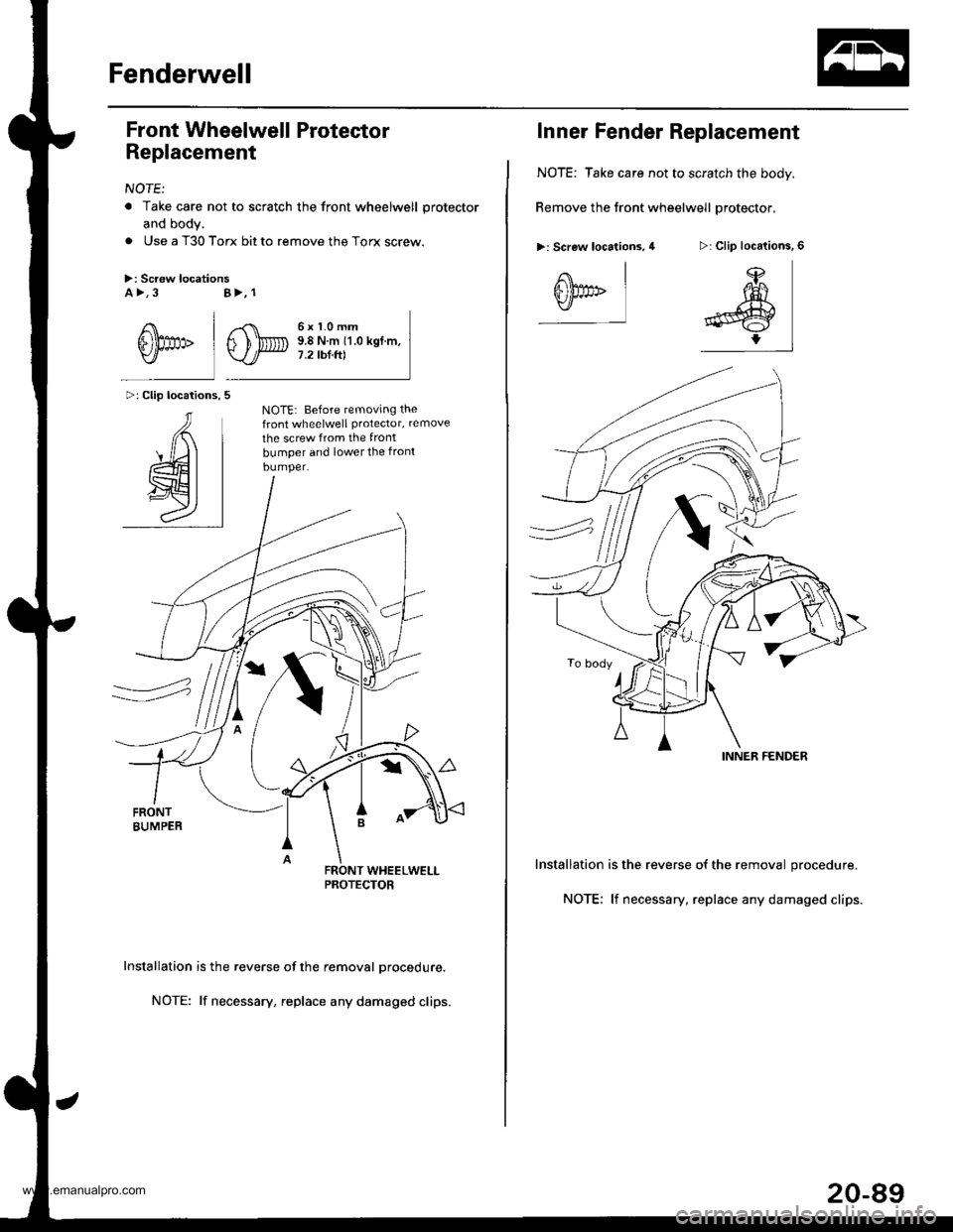
Fenderwell
Front Wheelwell Protector
Replacement
NOTE:
a Take care not to scratch the front wheelwell protector
and body.
. Use a T30 Torx bit to remove the Torx screw.
>: Screw locationsa >,3
/\l
6'thp IY/
>: Clip locations,
AI
4t I
wt I
al
B>, 1
,,-C\
s)Dv.l/
6x1.0mm9.8Nm(1.0kgf.m,7.2 tbf.ft)
NOTE: Before temoving thefront wheelwell Protector, remove
the screw from the front
bumper and lower the front
bumper.
Installation is the reverse of the removal Drocedure.
NOTE: lf necessary, replace any damaged clips.
Inner Fender Replacement
NOTE: Take care not to scratch the body.
Remove the front wheelwell protector,
>: Screw locations, 4
Installation is the reverse of the removal procedure.
NOTE; lf necessary, replace any damaged clips.
>: Clip locations,
ffi)fl(
l#:rl
A\
s))pp>Y]
INNER FENDER
20-89
www.emanualpro.com
Page 1071 of 1395
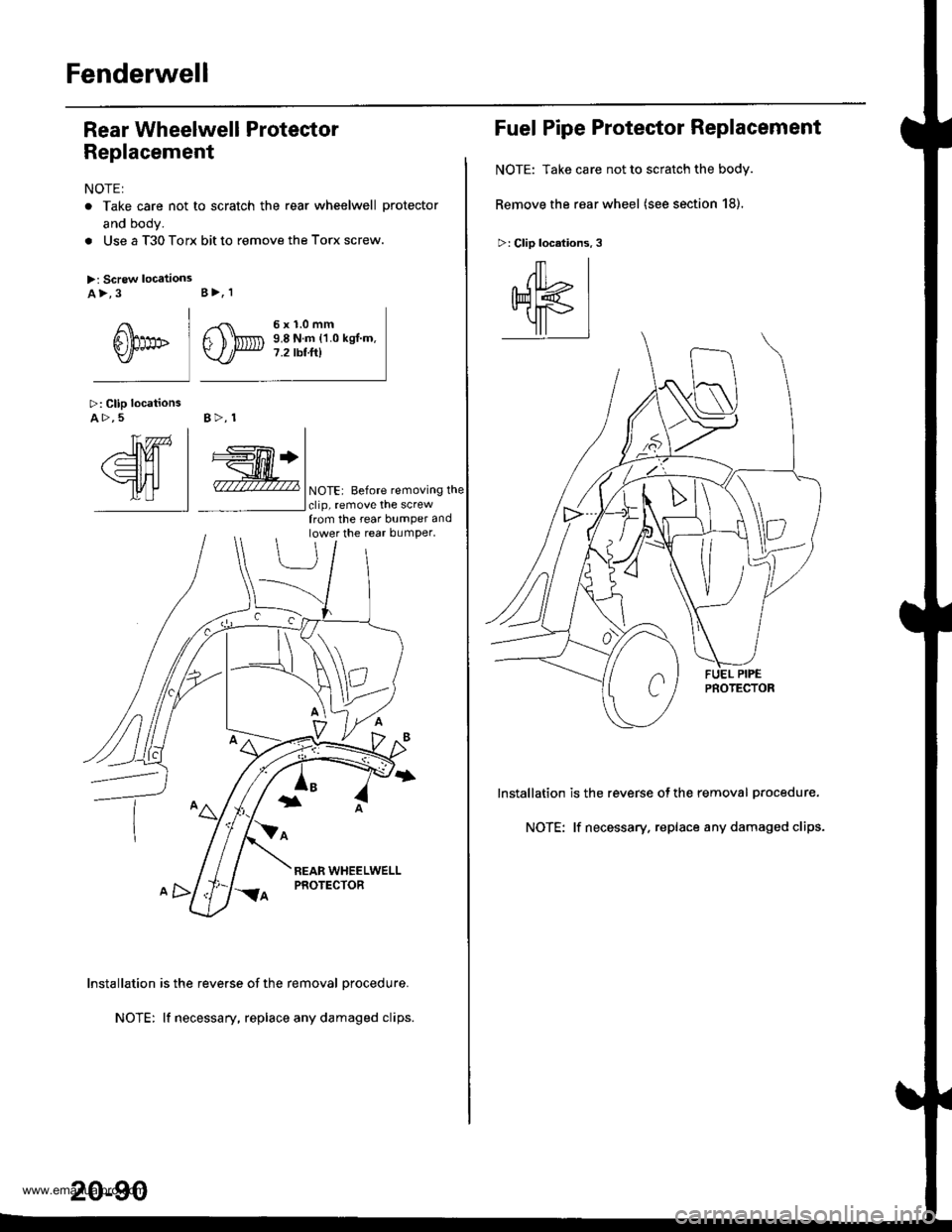
Fenderwell
Rear Wheelwell Protector
Replacement
NOTE:
. Take care not to scratch the rear wheelwell protector
and body.
. Use a T30 Torx bit to remove the Torx screw.
>: Screw locationsa>,3
I
6him" lY/
>: Clip locationsA >,5 B>, 1
B>, I
,.{\
F ),@Y-./
6x1.0mm9.8 N.m {1.0 kgl.m.7.2 rbtft)
YnTn | |
/'d)Ul | +['Tl+l
\=lHl | _H_l
tlrflJ | - INoTE: Before removinsthe- | lclip. remove the screw
lnstallation is the reverse of the removal procedure.
NOTE: lf necessary, replace any damaged clips.
from the rear bumper andlower the rear bumper,
20-90
Fuel Pipe Protector Replacement
NOTE: Take care not to scratch the body.
Remove the rear wheel (see section 18).
>: Clip locations,3
/ll
qK
1l
lnstallation is the reverse of the removal Drocedure.
NOTE: lf necessary. replace any damaged clips.
www.emanualpro.com