Arm HONDA CR-V 1998 RD1-RD3 / 1.G Repair Manual
[x] Cancel search | Manufacturer: HONDA, Model Year: 1998, Model line: CR-V, Model: HONDA CR-V 1998 RD1-RD3 / 1.GPages: 1395, PDF Size: 35.62 MB
Page 513 of 1395
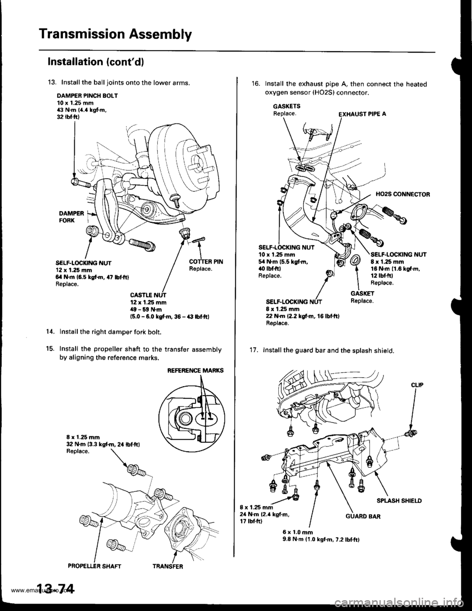
Transmission Assembly
Installation (cont'dl
13. Installthe balljoints onto the lower arms.
DAMPER PINCH BOLT10 x 1.25 mm43 N.m {a.a kgf.m,32 rbfft)
SELF.LOCKING NUT'12 x 1.25 |nm6il N'm 16.5 kgtin, 47 lbtftlReolace.
Replace.
14.
PROPELI"ER SHAFT
13-74
12 x 1.25 mm,19 - 59 N.m(5.0 - 6.0 kgi.m, 36 - € lbfttl
Install the right damper fork bolt.
Install the propeller shaft to the transfer assembly
by aligning the reference marks.
E x 1.25 mr'|
15.
REFERENCE MARKS
32 N.m 13.3 kst m, 2a lbf.ftl
TRANSFER
Install the exhaust pipe A, then connect the heated
oxygen sensor (HO2S) connector.
GASKETSReplace.
HO2S CONNECTOR
10 x 1.25 mm5,1N.m 15.5 kgtm.() tbt filReplace.
SELF.LOCKING
SELF.LOCKING NUT8 x 1.25 mm16 N.rn 11.6 kg{.m,12lbtfr)Replace.
GASKETReplace.
8 x 1.25 rr|ln22 N.m (2.2 tgf.m, 16 lbl.ftlReplac6.
'17. Installthe guard bar and the splash shield.
SPLASH SHIEI.I)I x 1.25 mm24 N.m l2.a kgf.m.17 tbtft)GUARD BAR
6x1.0mm9.8 N.m (1.0 kgf.m, 7.2 lbf.ft)
www.emanualpro.com
Page 518 of 1395
Ref. No.
^tl)
@
*rar
@
@
,-o
@
o
@
@
@
@
@.--@
@
@
@
@
@
@
@
@
@
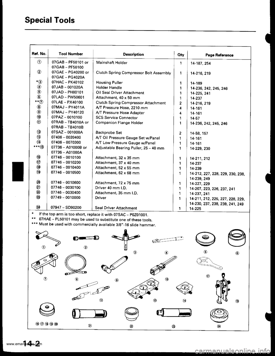
Tool NumberDescriptionOty I Pago Referonc€
Mainshaft Holder
Clutch Spring Compressor Bolt Assembly
Housing Puller
Holder Handle
Oil Seal Driver Aftachment
Attachment, 40 x 50 mm
Clutch Spring Compressor Attachment
Ay'T Pressure Hose, 2210 mm
IVT Pressure Hose Adapter
SCS Service Connector
Companion Flange Holder
Backprobe Set
lVT Oil Pressure Gauge Set w/Panel
A,/T Low Pressure Gauge w/Panel
Adjustable Bearing Puller, 25 - 40 mm
Anachment, 32 x 35 mm
Attachment, 37 x 40 mm
Attachment. 52 x 55 mm
Attachment. 62 x 68 mm
Attachment, 72 x 75 mm
Driver 40 mm l.D.
Attachment, 35 mm LD.
Driver
07GAB - PF50101 or
07GAB - PF50100
07GAE - PG40200 or
OTGAE _ PG4O2OA
07HAC - PK40102
07JAB - 001020A
07JAD - PH80101
07LAD - PW50601
07LAE - PX40100
OTMAJ - PY4O114
07MAJ - PY40120
07 PAZ - 0010100
07RAB - TB4010A or
07RAB.TB40lOB
07sAz - 001000A
07406 - 0020400
07406 - 0070300
07736 - 4010008 or
07736 - A010004
07746 - 0010100
07746 - 0010200
07746 - 0010400
07746 - 0010500
07746 - 0010600
07746 - 0030100
07746 - 0030400
07749 - 0010000
07947 - SD90200Seal Driver Aftachment
1
1
1
1,l
1
I
2
1'l
1
I
1
1
1
1
1
1
I
1
14-181 , 254
14-216,219
14-189't4-236,242,245,246
't 4-225, 241
14-237
14-216,2't9
14-161
14- 161
14-57
14-236,242,245,246
14-58, 157
14-161
14-161'14-229,230
14-211, 2't2
14-231
14-239
14-212, 227 , 228,229, 230, 238,
14-239, 249
14-221 ,229't 4-207 , 223,226, 237 , 241
14-237,241
1 +21 1, 2't2, 225, 227, 228, 229,
14-230, 237 , 238, 239, 24't, 249't4-225
lf the top arm is too short, replace it with 07SAC - pOZ01OO1.
07HAE - PL50101 may be used to substitute one of these tools.Must be used with commercially available 3/8"-16 slide hammer.
E----G
@@@@@
@
tvj
'
@@@)
14-2
www.emanualpro.com
Page 533 of 1395
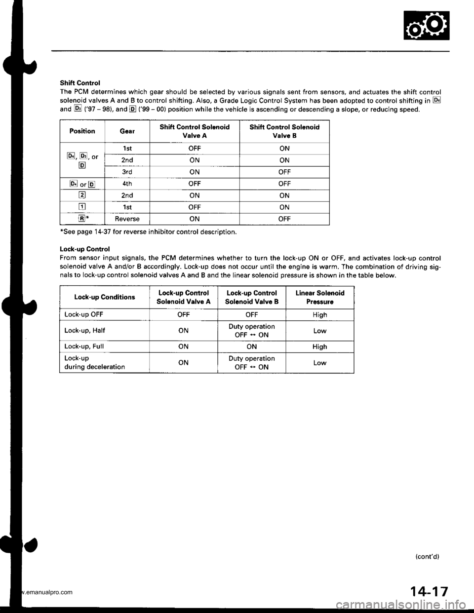
Shift Control
The PCM determines which gear should be selected by various signals sent from sensors, and actuates the shift control
solenoid valves A and B to control shifting. Also. a Grade Logic Control System has been adopted to control shifting in E
anO E ('gZ - gg), and E ('99 - 00) position while the vehicle is ascending or descending a slope, or reducing speeo.
PositionGearShift Control Solenoid
Valve A
Shift Control Solonoid
Valve B
E, E, Or
E
'I stOFFON
2ndONON
3rdONOFF
E orE4thOFFOFF
a2ndONON
tr1stOFFON
E-ReverseONOFF
*See page 14-37 for reverse inhibitor control description.
Lock-up Control
From sensor input signals, the PCM determines whether to turn the lock-up ON or OFF, and activates lock-up control
solenoid valve A and/or B accordingly. Lock-up does not occur until the engine is warm. The combination of driving sig-
nals to lock-up control solenoid valves A and B and the linear solenoid pressure is shown in the table below.
Lock-up ConditionsLock-up Control
Solonoid Valve A
Lock-up Control
Solenoid Valve B
Linear Solenoid
Pressuro
LOCK-Up \JrrOFFOFFHigh
Lock-up, HalfONDuty operation
OFF - ON
Lock-up, FullONONHish
Lock-up
during decelerationONDuty operation
OFF - ONLow
(cont'd)
14-17
www.emanualpro.com
Page 543 of 1395
Regulator Valve
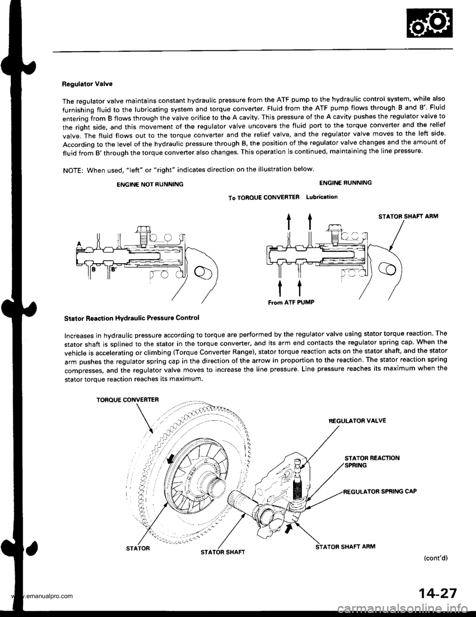
The regulator valve maintains constant hydraulic pressure from the ATF pump to the hydraullc control system, while also
furnishing fluid to the lubricating system and torque converter. Fluid from the ATF pump flows through B and B'. Fluid
entering from B flows through the valve orifice to the A cavity. This pressure of the A cavity pushes the regulator valve to
the right side. and this movement of the regulator valve uncovers the fluid port to the torque converter and the relief
valve. The fluid flows out to the torque converter and the relief valve, and the regulator valve moves to the left side.
According to the level of the hydraulic pressure through B, the position of the regulator valve changes and the amount of
fluid from B,through the torque converter also changes. This operation is continued, maintaining the line pressure.
NOTE; When used, "|eft" or "right" indicates direction on the illustration below.
ENGINE NOT RUNNING
STATOR SHAFT ABM
Stator Reaction Hydraulic Pressurs Control
Increases in hydraulic pressure according to torque are performed by the regulator valve using stator torque reaction. The
stator shaft is splined to the stator in the torque converter, and its arm end contacts the regulator spring cap When the
vehicle is accelerating or climbing (Torque Converter Range), stator torque reaction acts on the stator shaft, and the stator
arm pushes the regulator spring cap in the direction of the arrow in proportion to the reaction. The stator reaction spring
compresses, and the regulator valve moves to increase the line pressure. Line pressure reaches its maximum when the
stator torque reaction reaches its maximum.
TOROUE CONVERTER
REGULATON VALVE
STATOR REACTION
TOR SPRING CAP
(cont'd)
ENGINE RUNNING
To TOROUE CONVERTER Lubtication
STATONSTASHAFTATOF SHAFT ARM
14-27
www.emanualpro.com
Page 597 of 1395
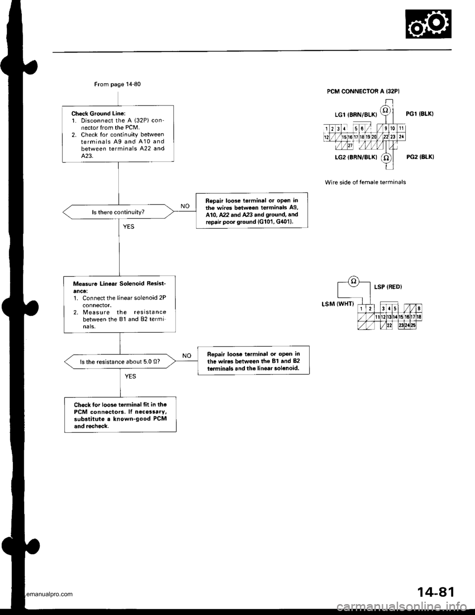
Ch€ck Ground Lin€:1. Disconnect the A (32P) con-nector from the PCM.2. Check lor continuity betweenterminals Ag and A10 andbetween terminals A22 andA.23.
Repair loose terminal or opon inth€ wires between terminals A9,A10, A22 and A23 and g.ound, andrepair poor ground lG101, G4011.
Measure Linear Solenoid R*ist-
ance:1. Connect the linear solenoid 2P
connector.2. Measure the resistancebetween the 81 and 82 terminals,
Ropair loos€ terminal or op6n in
the wiles between th€ 81 and 82
l6rminals and the linear solenoid.ls the resistance about 5.0 0?
Chock lor loose tarminalfit in thePCM connectors. lf necosaarv,subsiituto a known-good PCMand recheck.
PGl IBLKI
PG2 (ALKI
Wire side of temale terminals
14-81
www.emanualpro.com
Page 620 of 1395
Electrical Troubleshooting ('98 - 00 Model)
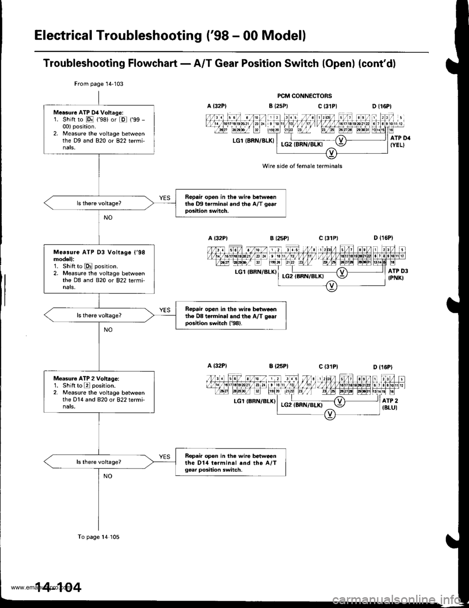
Troubleshooting Flowchart - A/T Gear Position Switch (Open) (cont'd)
PCM CONNECTORS
B {25Ptc (31P|
LGl IERN/BLKI
Wire side of female terminals
LGl {BRN/BLKI
LGl {BRN/ELXI
From page 14-103
Me.sure ATP D4 Vohrge:1. Shift to E 1'98) or E ('99 -
00) position.2. Measure the voltage betweenthe Dg and 820 or 822 termi-nats.
Repair opon in th6 wire betweentho m tarminal and the A/T gealposition swhch.
Me..ure ATP 03 Vohage l'98modell:1. Shift to E position.2. Measure the voltage betweenthe DB and 820 or 822 tetmi-nals,
Repair open in the wire botwoonth6 08 terminal .nd the A/T geatposition switch (381.
Measuro ATP 2 Voltage:1. Shilt to E position.2. Measure the voltage betweenthe D14 and 820 or 822 terminats.
Repair opon in the wire betweenthe D14 t€.minal end the A,/Tgear po3ition switch,
To page 14 105
www.emanualpro.com
Page 621 of 1395
From page 14-104
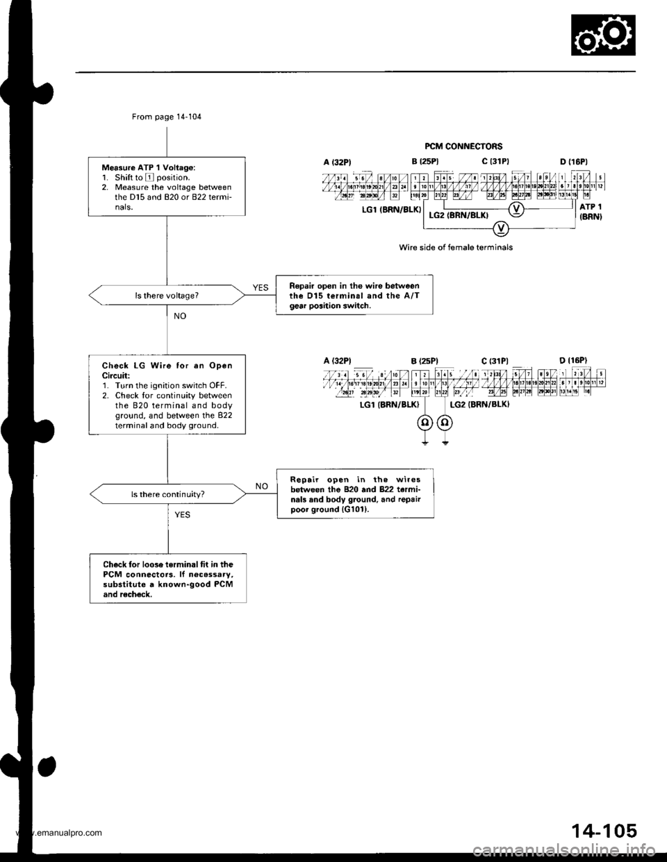
Measure ATP 1 Voliag€:1. Shift to E position.2, Measure the voltage betweenthe D15 and 820 or B22 termi-nals.
Repair open in the wire betweenthe D15 terminal and the A/Tgear poaition switch.
Check LG Wire tor an OpenCircuit:'1. Turn the ignition switch OFF.2. Check lor continuity betweenthe 820 terminal and bodyground, and between the 822terminal and body ground.
Repair open in th. wiresbetween the B20 and 822 tarmi-nals and body ground. and repairpoor ground {G101).
ls there continuity?
Check tor loose terminaltit in thePCM connectors. lf n6cassary,substitute d known-good PCMand recheck.
B t25Pl
FCM CONNECTORS
c t3lPtD tl6Pl
LGl IBRN/BLKI
LGl (BRN/BLKI
Wire side of female terminals
A (32P1B (2sP)c (31P|
14-105
www.emanualpro.com
Page 631 of 1395
A {32P}
From page 14-114
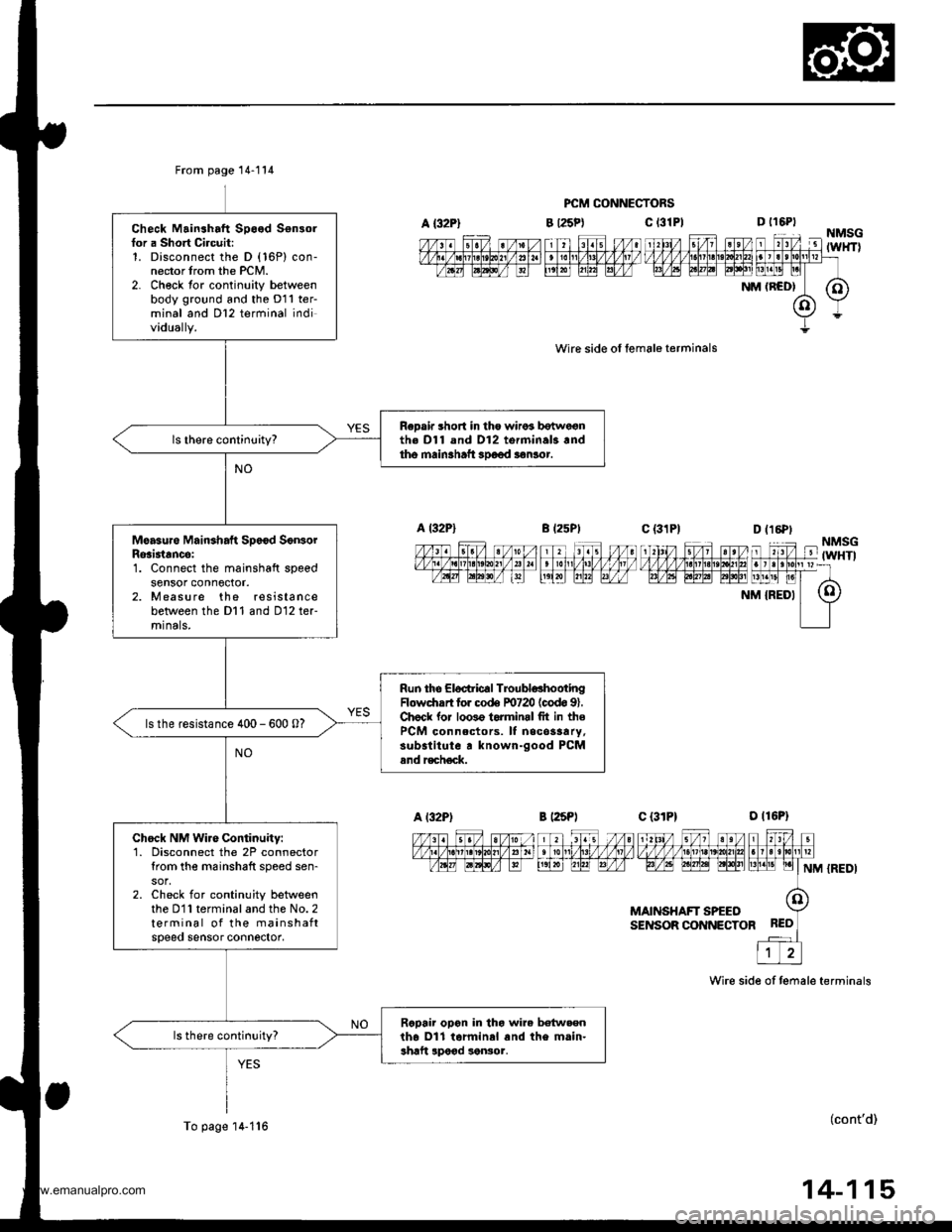
Check Mainshaft Speed Sensorfor a Short Circuit:1. Disconnect the D (16P) con-nector trom the PCM.2- Ch€ck tor continuity betweenbody ground and the D11 ter-minal and Dl2 terminal individually.
ReDair short in tho wiros botwe€nth€ Dl1 and D12 torminal3.ndtho main3haft 3Doed aonlor.
Moasure Mainshaft Sp6€d SonsorRosi3tancei1. Connect the mainshaft speedsensor conn6ctor.2. Measure the resistancebetween the Dl1 and D12 ter-mrnals,
Run the Eloctric€l TroubldhootingFlowdrrrt for co& F0720 (codo 91.Chock lor loo3o torminrl fit in thePCM connectors. It necos3ary,substitute r known-good PCMand r€ch€ck.
ls the resistance 400 - 600 0?
Chock NM Wire Continuity:1. Disconnect the 2P connectortrom the m6inshaft speed sen-
2. Check for continuity betweenthe D11 terminal and the No. 2terminal of the mainshaftspeeo sensor connector,
Rcpair opon in tho wire betw.enth6 Dll tarminal and the main-shaft lpood sonsor.
To page'14-1'16
PCM CONNECTORS
c t3lPl
wire side ol female terminals
B l25Pt
D t16PtNMSG-'lTZ lit4'l Fl l'1til FTil ,'l unrv v v v v l.t1lLtLt?!/]|,1tut larrlrllllpr=rtavtq tptntat EElt [1!]t! pl
NM (RCD| (O)
(o)Y
Y=
c {31P1--_|--1\‰1,/ s/1 st/v,1zzfififinffiiFrF/l,6t FFF| LrLrEllNM {REDI
MAINSHAFT SPEEOSENSOR CONNECTOR
Wire side of temale terminals
(cont'd)
14-115
www.emanualpro.com
Page 673 of 1395
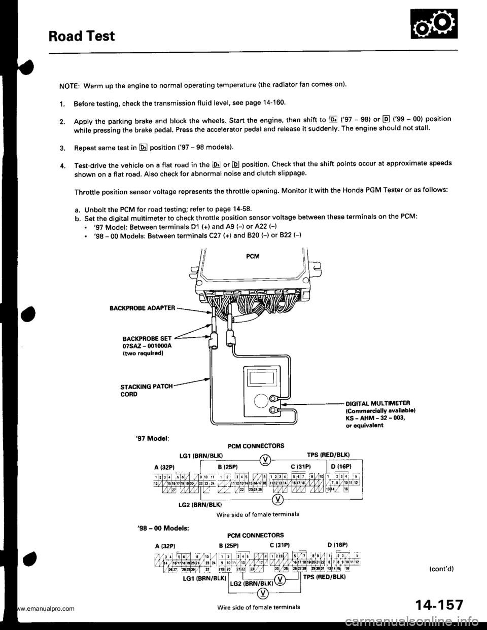
Road Test
NOTE: Warm up the engine to normal operating temperature (the radiator tan comes on).
1. Before testing, check the transmission fluid level, see page 14-160.
2. Apply the parking brake and block the wheels. start the engine, then shift to E {'97 - 98) or E {'gg - 00) position
while pressing the brake pedal. Press the accelerator pedal and release it suddenly. The engine should not stall.
3. Repeat same test in E position ('97 - 98 models).
4. Test-drive the vehicle on a flat road in the E or E position. Check that the shift points occur at approximate speeds
shown on a flat road. Also check for abnormal noise and clutch slippage.
Throttle position sensor voltage represents the throttle opening. Monitor it with the Honda PGM Tester or as follows:
a. Unbolt the PCM for road testing; reJer to page 14-58.
b. Set the digital multimeter to check throttle position sensor voltage between these terminals on the PCM:
. '97 Model: Between terminals D'! (+) and A9 (-) or A22 {-}
. '98 - OO Models; Between terminals C27 (+) and 820 (-) or 822 {-)
BACKPROBE ADAPTER
BACKPROBE SETorsAz - 001moA(two roquircdl
STACKING PATCH
CORD
DIGiTAL MULTIMETER
{Comm€rcirllY .vailablc}KS-AHM-32-003,or equival.nt
'97 Model:PCM CONNECTORS
'98 - 0O Models:
A l32Pt
Wire side of female terminals
PCM CONNECTORS
B {25Pt c l31P}
(cont'd)
LGl (BRN/BLK)
'. //B 1 l'o ti , jl. to a 2r / / 11111t1.t nait la t1 t213tr / t6t, tl / / / / 1 3 / 10n v
t-'a:IM-&E -Llfiffi-fl)\"".'E
Wire side ot female termanals14-157
www.emanualpro.com
Page 675 of 1395
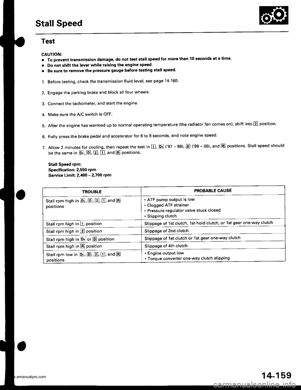
Stall Speed
Test
CAUTION:
. To prevent transmission damage, do not te3t stall speed for mors than 10 s€€onds at a time'
. Do not shift the lever while raising th€ engine spsed.
. Be sure to remove tho pressuro gauge bofore testing stall speed,
1. Before testing, check the transmission fluid level, s€e page 14-160.
2. Engage the parking brake and block all four wheels
3. Connect the tachometer, and start the engane.
4. Make sure the Ay'C switch is OFF
5. After the engine haswarmed upto normal operating temperature (the radiator fan comes on),shiftinto@ position.
6. Fully press the brake pedal and accelerator for 6 to 8 seconds, and note engine speed '
j. A|ow 2 minutes for cooling, then repeat the test in E, E ('97 - 98). E {'99 - 00}, and E positions. Stall speed should
be the same in E, E, E, tr. and E positions
Stall Speed rpm:
Specitication: 2,550 rpm
S€rvice Limit: ?,400 - 2.700 rpm
TROUBLEPROBAELE CAUSE
Stall rpm high in El, E, E, E and E
positions
ATF pump output is low
Clogged ATF strainer
Pressure regulator valve stuck closed
Slipping clutch
Stall rpm high in E positionSlippage of 1st clutch, 1st-hold clutch, or 1st gear one-way clutch
Stall rpm high in E positionSlippage of 2nd clutch
stall rpm high in E! or E positionSlippage of 1st clutch or 1st gear one-way clutch
Stall rpm high in E positionSlippage of 4th clutch
Stall rpm low in [dd, E. E, E, ana E
positions
. Engine output low
. Torque converter one-way clutch slipping
14-159
www.emanualpro.com